
The Feasibility of Electrical Safety Grounding Tool for Medium
Voltage Distribution with A3CS Cables
I Wayan Jondra, I Nengah Sunaya and I Made Aryasa Wiryawan
Electrical Departmen, Politeknik Negeri Bali, Bukit Jimbaran, Badung, Indonesia
Keywords: Electrical, Grounding Tool, Work Safety.
Abstract: In this globalization Electrical energy has become like a primary need. Electrical energy consumption growth
has coherency with economic growth. The electricity supply system is designed to improve the reliability
without blackout. Reliability improvement can be done by construction, maintenance, repair and improvement
of the system. Construction, maintenance, repair and improvement of the distribution system must be
guaranteed work safety and health. In Australia, electrical safety and health are very tightly regulated, because
it very dangerous if the equipment is not grounded properly. The preparation of electrical safety grounding
for medium voltage distribution with A3CS cables is very important, because now only available for A3C
cables. This research is quantitative research through statistical and mathematical data processing. This study
examines the feasibility of electrical ground safety assembled for medium voltage distribution with A3CS
cables. The results found that electrical safety grounding tools is feasible to use in construction, maintenance,
repair and improvement of over head medium voltage distribution system with A3CS and A3C cable. This
grounding tools has an insulation resistance more than 100 mega ohms, a leakage current smaller than 1 milli
amperes, and the distance of workers to the active part is more than 0.9 meters.
1 INTRODUCTION
1.1 Problems Background
The electricity is very important in this globalization
era, the electricity has become like a primary need.
So many economic activity need electrical power.
Electrical energy consumption had a positive impact
and there was bidirectional causality with economic
growth (Yılmaz Bayar and Hasan Alp Özel, 2014).
The growth of energy consumption will be followed
by increase electricity consumption as a result of
economic growth (Zhenya Liu, 2016). An electrical
energy consumption increased during the economic
growth.
So many economic activities need electrical
energy. In Aceh Province of Indonesian the empirical
evidences indicate that the long-run bidirectional
relationship exists between, commercial electricity
consumption and economic growth and, in the short-
run bidirectional relationship between economic
growth and all of the sectoral electricity consumption
(Fahrul Rizal, 2014). That so very vital the electrical
energy, the engineer did some experimental to build,
maintenance and repair the system for a safe and
reliable electrical energy distribution(Math H Bollen,
2000).
This reliability system is designed to guarantee
the electricity supply quality that meets to the
standards. The quality of electricity supply aims to
protect consumer rights and so the State Electricity
Company’s (PLN’s) advantages. So that all parts of
the electrical energy supply system must meet the
standards of reliability and security. The hope to
electricity distribution by PT.PLN must not be
interrupted for 24 hours. Routine maintenance such
as a vegetation management program can reduce
unnecessary tripping especially during excess
channel situations (Chan F.C., 2008). These steps can
minimize the external interference. Thus, the
maintenance, repair and improvement of the
distribution system is an important action.
Maintenance, repair and improvement of the
distribution system must be safety and healthy work
processed. The work process must follow to standard
operational procedures with available standards tools.
In Australia, occupational safety and health in
working electricity is very tightly regulated, because
accidents to burns or falling from a height site, thus
the equipment must be earthed properly (Alex Ward,
Jondra, I., Sunaya, I. and Wiryawan, I.
The Feasibility of Electrical Safety Grounding Tool for Medium Voltage Distribution with A3CS Cables.
DOI: 10.5220/0010965200003260
In Proceedings of the 4th International Conference on Applied Science and Technology on Engineering Science (iCAST-ES 2021), pages 1345-1351
ISBN: 978-989-758-615-6; ISSN: 2975-8246
Copyright
c
2023 by SCITEPRESS – Science and Technology Publications, Lda. Under CC license (CC BY-NC-ND 4.0)
1345

1982). My assembled that grounding tool for
electrical work safety at A3CS cable on medium
voltage distribution, will protect the workers from
electric shock and lightning strikes. There are many
people are not aware of the threat electricity danger,
so this awareness is very important, and safety and
healthy tools are prepared (Saba et. al., 2014).
A good grounding system if the equipment is well
connected to the earth. Electrical Working safety if
the whole system equipment bended and connected to
the ground. The quality of earthing is the basic
protection against AC interference (Mohamed, 2018).
The source of interference is lightning, switching, or
an error in the distribution system. To do this bending
and grounding must be done with adequate tools to a
good connection between the equipment and the
earth. The problem now is that are the overhead
medium voltage distribution in Indonesia, has been
replaced by an insulated cable like all alloy aluminum
conductor sheated (A3CS). This will be an obstacle
for bending and grounding conductor to earth,
because the current grounding equipment is properly
to A3C conductors.
This research is very important to get a model of
earthing tool for electrical work safety in over head
medium voltage system, that can grounded whole
equipment with properly to the earth, due
construction work, maintenance, repair and
improvement of over head medium voltage electrical
distribution system. This paper to explore how to
assembly dan tested the grounding tool for electrical
work safety at A3CS cable on medium voltage
distribution..
1.2 Problem
How the feasibility Of Electrical Safety Grounding
Tool For Medium Voltage Distribution With A3CS
Cables?.
2 RESEARCH METHOD
2.1 Research Approaches and
Concepts
To analyses that problems, this study was designed as
a qualitative approach study. The problems will be
discussed by the data from measurement dan tested,
ware calculation to obtain the good insulation for
medium voltage work safety handle, and all of
component connected. This research tested is done in
the Politeknik Negeri Bali Workshop and PLN UP2D
laboratory, and the test results statistically and
mathematically analyse to obtain the feasibility of
electrical safety grounding tool assembly, comparing
to the electrical work safety roles, and than taken
conclusions and recommendations. This grounding
tool is assembled by plastic pipe, rubber rings, life
line connector, and flexible copper cable. This
grounding tool is an innovation assembly for
electrical work safety tool. This grounding tools is
properly applied at medium voltage distribution with
all alloy aluminium conductors (A3C) and all alloy
aluminium conductors Sheeted (A3CS), but the other
only for A3C.
2.2 Total Sample
This research was conducted by tested three samples
“Electrical Safety Grounding Tool For Medium
Voltage Distribution With A3CS Cables” that was
taken from a product assembly.
2.3 Variable Operational Definition
In this study, we observed magnitude of the
connection, leakage current an insulation test,
dielectric strength and clearance distance. The
connection test is applied between connection head of
grounding tool and the medium voltage distribution
circuit. The test voltage is the amount of voltage
applied to the sample through the high voltage tester.
Leakage current is the amount of current flowing in
to the test sample, due to given test voltage. Dielectric
and clearance distance measured by ruler meter.
2.4 Tested
The connection test is tested by ohm meter, where the
good connection is indicated by resistance value at
about zero ohm. Electrical test voltage against
minimal insulation resistance is tested with a voltage
equal to the operating voltage. For testing a minimum
20 kV system equipment is tested with a voltage tester
at 20 kV. Tests are carried out using electronic high
voltage tank, volt meters and ampere meters. All
equipment connected with grounding system. Tested
are made between phase and ground.
For the connection tested, each sample
(connection head) is connected and screwed until the
pin piercing to the A3CS insulation. The connection
head is connected with red probe and the A3CS
conductor connected with black probe of ohm meter.
Selector switch of AVO meter was turned around to
1x of ohm meter. That connection tested process have
been done in three time reply.
For Current leakage tested, each test sample
iCAST-ES 2021 - International Conference on Applied Science and Technology on Engineering Science
1346
(grounding shaft) is placed between the connection
head and winding electrode at the handle. The
connection head is given a 0.2 Hz AC voltage and the
winding electrode is grounded trough ampere meter.
The voltage given to the samples is increased step by
step, with each step is 5 kV, starting from 5 kV to 30
KV. In every voltage step, the current leakage flow
was measured with ampere meter. This current
leakage tested was processed three time at dry and
wet conditions of grounding shaft. Voltage detector is
applied to ensure the level of voltage leakage trough
current leakage from the head connection to the
grounding shaft.
2.5 Data Analysis
Data obtained from the test results are processed
quantitatively. Data is processed mathematically by
the process of multiplication and divide. The data is
also processed statistically by finding the smallest
value from all of data if the limit is minimum such as
insulation resistance, dielectric strength, space
clearance, and finding for the biggest value from all
of data if the limit is maximum such as at leakage
current condition.
3 RESULT AND DISCUSSION
The result of this research described by figure and
table. The analyses of the feasibility of a grounding
shaft was carried out is to guarantee the work safety.
Grounding tools must have good ground resistance
and the insulated shaft to ensure work safety in the
construction, maintenance, repair and improvement
of the medium voltage distribution. However, there is
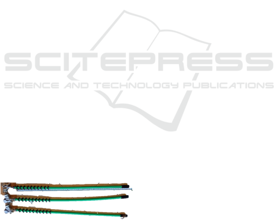
no perfect shaft material, therefore the research on
this assembled shaft so important. This earthing shaft
constructed by polypropylene pipe, which has good
electrical characteristics because the coefficient of
resistivity volume is 8.5x10
14
Ohm-cm. Safety
grounding shaft was designed like as shown in Figure
1 below.
Figure 1: Safety grounding shaft.
In accordance to the safety grounding shaft
function is insulation. A perfect shaft insulating
material has an unlimited resistance, that currently
cannot obtained. There is a small leakage current that
flows in insulation material. The problem is the
resistance of insulating material is not unlimited. The
insulation resistance is according to Ohm's Law is
voltage divided by leakage current (Salman and
Muhammad, 2011) and can be shown as an equation
below.
V = I x R (1
)
R = V / I (2
)
where :
R = Insulating Resistance (Giga Ohm)
V = Voltage charge due the sample (Kilo Volt)
I = Leakage Current (micro Amperes )
The normal air dielectric strength coefficient is 30
kV/cm, the total dielectric strength is total distance
multiple with dielectric strength coefficient, as shown
in the formula below (Kumail et. al., 2018).
ℰ=ℰ
0
x d (3
)
where :
ℰ = Dielectric strength (KV)
ℰ
0
= Dielectric strength coefficient (KV/cm)
d = distance (cm)
3.1 Result
Conducting to the tested, insulation resistance after
the leakage current tested with the High Voltage VLF
Hi-pot Instruments Type: VLF4022, dielectric
strength, and safe distance between active voltage
equipment with workers. These four benchmark must
be considered to determining the feasibility of the
electrical work safety grounding shaft. The minimum
insulation for medium voltage is 100 Mega Ohms
(Sanjay et. al., 2018). The maximum leakage current
flow does not affect a shock to the human body is 1
milli amperes (Saba et. al., 2014). Total the dielectric
strength must exceed than the active voltage to avoid
the electric discharge (Saba et. al., 2014). The
minimum safe distance between workers and 15 Kilo
Volt active equipment is 90 cm (Manik et. al., 2015).
Conducting to the trial this safety grounding tools
connecting to the medium voltage distribution
network, occurred a good connection. Measurement
results of connections on A3CS and A3C cables is
limit to zero. Thus the head of the grounding shaft can
properly pierce the A3CS cable insulation and well
grip well on to A3C conductor.
Isolation resistance pretest was conducted at the
Electrical Engineering Workshop Bali State
Polytechnic, Before insulation resistance tested in the
UP2D Bali PLN laboratory. A pretest is carried out to
conduct an early detection of the insulation resistance
The Feasibility of Electrical Safety Grounding Tool for Medium Voltage Distribution with A3CS Cables
1347
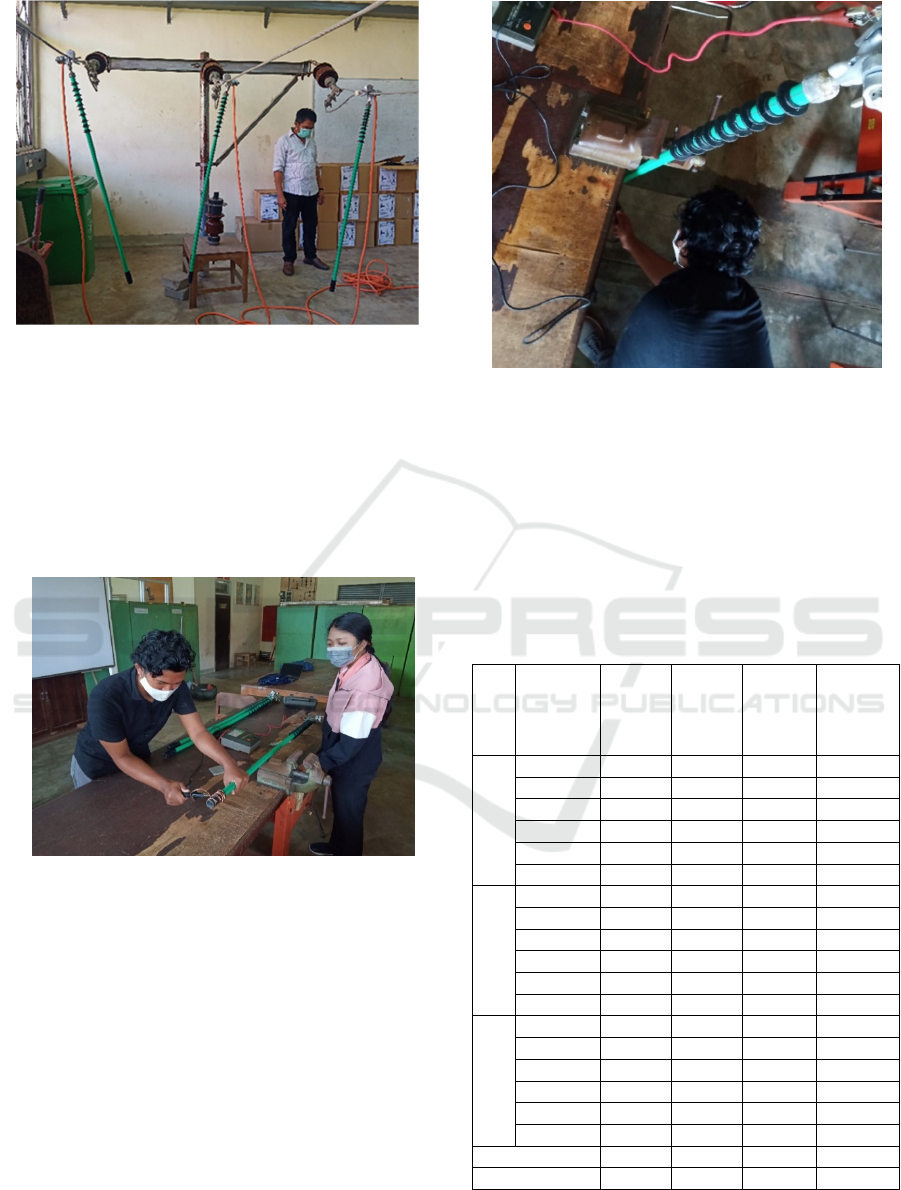
Figure 2: Electrical safety grounding on the trial.
quality this electrical work safety grounding shaft.
The pretest is carried out by applying a voltage of
5,000 volts and 10,000 volts to the terminal head and
handle connected by grounding trough coil electrode
as shown in the following figure 3. Insulation
resistance pretest is done in dry and wet condition
three times for each sample, the wet condition testing
as shown at figure 4.
Figure 3: Dry insulation resistance pretest with megger
10,000 volt.
The pretest is very important because it is not easy
to get permission to do it again at PLN UP2D Bali.
Pretest is done using 10,000 Volt meggers. the results
of the insulation resistance pretest using megger are
analyzed to obtain leakage currents, such as the
calculation below.
Leakage current analysis, sample 1 at 1
st
step
Voltage tested: 5,000 Volt DC
Insulation resistance : 250,000 Mega Ohm
The leakage current calculation:
Figure 4: Wet insulation resistance pretest with megger
10,000 volt.
I = V/R
= 5,000/250,000,000,000
= 0.02x10⁻⁶ amperes
= 0.02 micro amperes
Through the same calculation, the leakage current as
displayed in table 1 at below.
Table 1: Leakage current analysis grounding shaft with
Megger 10 kV.
Sam
ple
Step of
testing and
condition
R Iso.
at 5 KV
(Giga
Ohm)
R Iso.
at 10 KV
(Giga
Ohm)
Leakage
current at
5 KV
(micro
am
p
e
r
es
)
Leakage
current at
10 KV
(micro
am
p
e
r
es
)
1
1 dr
y
250 500 0.0200 0.0200
2 dr
y
200 400 0.0250 0.0250
3 dr
y
225 450 0.0222 0.0222
1 wet 78 156 0.0641 0.0641
2 wet 80 160 0.0625 0.0625
3 wet 80 160 0.0625 0.0625
2
1 dr
y
220 440 0.0227 0.0227
2 dr
y
300 600 0.0167 0.0167
3 dr
y
250 500 0.0200 0.0200
1 wet 40 80 0.1250 0.1250
2 wet 45 90 0.1111 0.1111
3 wet 45 90 0.1111 0.1111
3
1 dr
y
300 600 0.0167 0.0167
2 dr
y
250 500 0.0200 0.0200
3 dr
y
275 550 0.0182 0.0182
1 wet 38 76 0.1316 0.1316
2 wet 40 80 0.1250 0.1250
3 wet 40 80 0.1250 0.1250
I leakage max. 0.1316 0.1316
R Iso min. 38 76
The insulation resistance tested with High Voltage
VLF Hi-pot Instruments like shown in figure 3 below
iCAST-ES 2021 - International Conference on Applied Science and Technology on Engineering Science
1348
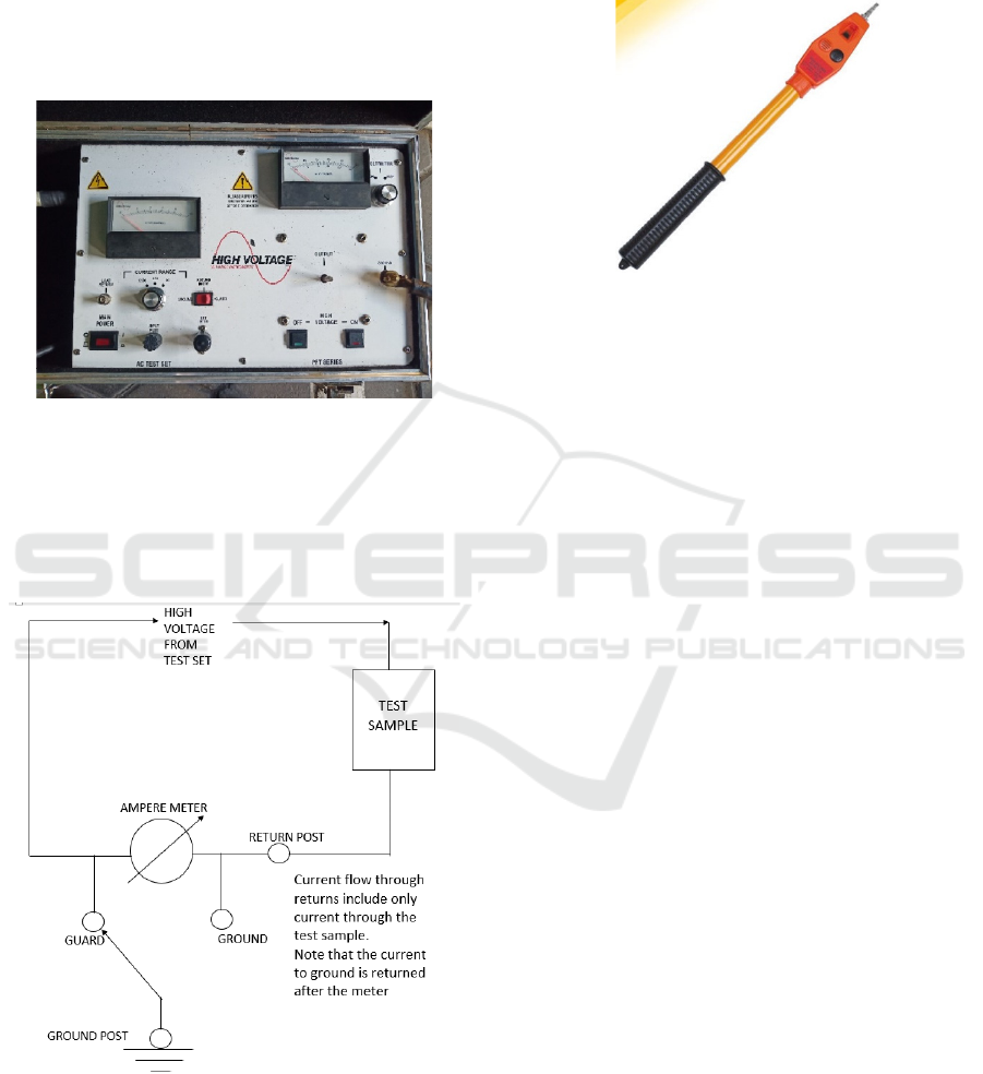
is done at PN UP2D Bali Laboratory. High voltage
VLF hi-pot instruments are high voltage test
equipment with low frequency. This measuring
instrument changes the voltage 220 Volt 50 Hz, into
a DC voltage, then converted back into low frequency
AC high voltage. The output of High Voltage VLF
Hi-pot Instruments test equipment Type: VLF 4022 is
40 KV AC with a frequency of 0.2 Hz.
Figure 5: High voltage VLF hi-pot instruments.
The leakage current testing circuit is carried out by
connecting the sample in series with a measuring
instrument. The test equipment is solidly grounded
for safety in the testing process. the return switch is
positioned on the guard as shown in figure 6.
Figure 6: Test diagram.
This leakage current tested start at a voltage test
of 5 kV, then increased by 5 kV per step up to 30 kV.
When testing a leakage current, also detecting a
leakage voltage using a voltage detector, which starts
working with a voltage of 2.7kV and above like
shown on figure 7. Tests were carried out on three
ground stick samples that had been assembled, with
dry and wet conditions.
Figure 7: Voltage detector.
Leakage current tested for dry test samples first.
After six voltage step dry test is finished the test
equipment is turned off, followed by making artificial
rain from the spryer, placed on top of test sample with
an angle of 30 degrees. After being wet, the test
sample was given a voltage from 5 kV to 30 kV, noted
the leakage current and the dielectric discharge
voltage was detected by voltage detector.
The analyses the insulation resistance tested with
High Voltage VLF Hi-pot Instruments, using the ohm
formula. Insulation resistance is equal to the tested
voltage given divided by the leakage current. The
calculation of insulation resistance to sample 1 tested
step 1 as described below.
Tested result:
Voltage tested : 5,000 Volt AC
Leakage current : 1 micro ampere
The calculation of insulation resistant:
R = V/I = 5,000/(1 x 10-6)
= 5 x10
9
Ohm = 5 Giga Ohm
In the same calculation process, the insulation
resistance for other step is as displayed in the table 2.
To determine the safe electrical work distancing
there are two conditions must be discussed for the
grounding shaft, that are the total distancing dielectric
strength and the distancing between the potential life
voltage equipment with the worker when to
connecting the “electrical safety grounding tool for
medium voltage distribution with A3CS cables” to
the medium voltage equipment.
The angle of rain is expected to be a maximum of
30 degrees. The wet condition decrease the dielectric
strength. There are 10 pieces rubber ring like an
umbrella will protect the shaft from solidly wet. Part
of the shaft dry protected by the rubber ring to
maintain dielectric strength. Thus, the dielectric
The Feasibility of Electrical Safety Grounding Tool for Medium Voltage Distribution with A3CS Cables
1349
strength distance of “the electrical safety grounding
tool for medium voltage distribution with A3CS
cables” can be calculated as described below.
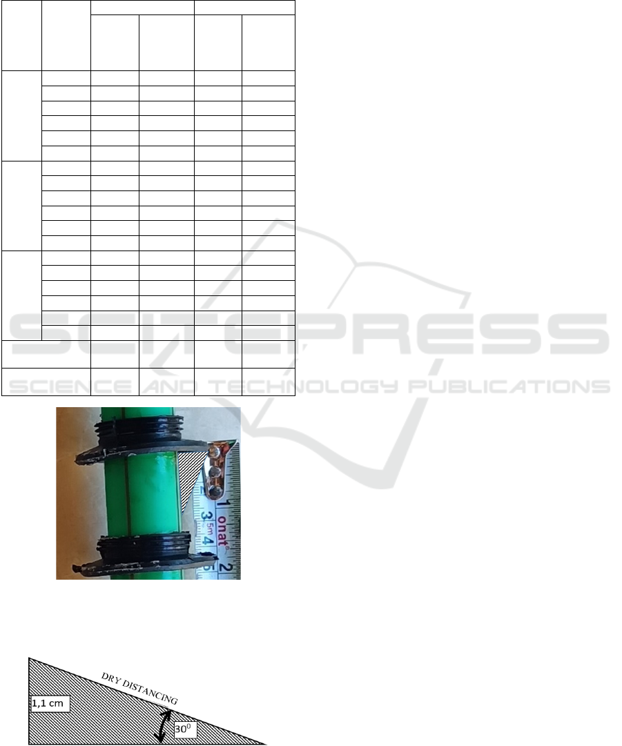
Table 2: Leakage current analysis grounding shaft with
Megger 10 kV.
Sam
ple
Voltage
Tested
(KV)
Dry Wet
Leakage
current
(micro
ampere)
Insulation
Resistance
(Giga Ohm
)
Leakage
current
(micro
ampere)
Insulation
Resistance
(Giga
Ohm)
1
5 1.00 5.00 1.00 5.00
10 1.00 10.00 2.00 5.00
15 2.00 7.50 4.00 3.75
20 2.00 10.00 4.00 5.00
25 2.00 12.50 5.00 5.00
30 3.00 10.00 4.00 7.50
2
5 1.00 5.00 3.00 1.67
10 2.00 5.00 4.00 2.50
15 2.00 7.50 4.00 3.75
20 3.00 6.67 5.00 4.00
25 4.00 6.25 6.00 4.17
30 4.00 7.50 5.00 6.00
3
5 1.00 5.00 1.00 5.00
10 1.00 10.00 2.00 5.00
15 2.00 7.50 3.00 5.00
20 2.00 10.00 4.00 5.00
25 3.00 8.33 5.00 5.00
30 3.00 10.00 4.00 7.50
Lowest insulation
resistance
5.00 1.67
Biggest leakage
curren
t
4.00 6.00
Figure 8: Rubber Ring on The Safety Grounding Shaft.
If the black-shaded triangle in figure 8 to copy and
pasted it will be obtained as shown in Figure 9 below.
Figure 9: Distancing angle.
Dry distancing calculation
Sin Q = Y/Z
Dry Distancing = 11/sin 300
= 1.1/0.5 = 2.2 cm
Total Dry Distancing = 10 x 2.2 cm = 22 cm
The normal air dielectric strength is 30 kV/cm
(Saba et. al., 2014). The total dielectric strength of
grounding shaft with 10 pieces rubber ring is:
ℰ=ℰ0 x d
= 30 x 22 = 660 KV
The total dielectric strength the shaft of “electrical
safety grounding for medium voltage distribution
with A3CS cables” with mathematic calculation is
660 kV. The result of voltage indicator tested at 30
kV AC given, 3 pieces rubber ring is lost dielectric in
wet condition.
Like as shown di Figure 1, the length of the shaft
is variability, that out of the three shaft, one stalk has
the smallest length of 123.5 cm. Thus the grounding
shaft is qualified to keep the distance between the
worker and the active part of the 15 kV phase to the
ground with a distance of 90 cm (Manik et. al., 2015).
Medium voltage distribution system in Indonesia
more lower only 11.6 KV from phase to ground.
3.2 Discussion
Based on the trial results it can be observed that work
safety grounding for medium voltage distribution
systems with A3CS cable, has been able to pierce
A3CS cable insulation to make a contact between the
clamp head and A3CS cable. Clamp heads also have
been trial to installed on A3C conductors. when
installed on the A3C conductor and A3CS cable AVO
Meter pointing to limit zero number.
Based on table 1 can be seen the maximum value
of leakage current is not more than 1 ampere and
minimum insulation resistance of grounding shaft is
not less than 100 Mega Ohm. The discussion can
proceed to the data shown in table 2. Based on table
2 can be seen the maximum value of leakage current
and minimum insulation resistance of grounding
shaft. Table 2 shows the minimum insulation
resistance occurs when the wet condition of shaft is
1.67 Giga Ohms and that the maximum value of
leakage current is 6 micro amperes. The benchmark
of minimum insulation for medium voltage is 100
Mega Ohms (Sanjay et. al., 2018). The benchmark of
maximum leakage current flow does not affect a
shock to the human body is 1 milli amperes (Kumail
et. al., 2018).
Based on the results of the analysis of safe
distance obtained two values to assessment the
iCAST-ES 2021 - International Conference on Applied Science and Technology on Engineering Science
1350

feasibility of the safety grounding shaft, namely: the
value of the dielectric strength and the distance of the
worker with an active part with potential voltage
discharge. The analysis founded that the safety
grounding shaft has dielectric strength of 660 kV, and
provides safe distance between the worker and the
active part of 123.5 cm. The benchmark of total the
dielectric strength must exceed than the active voltage
to avoid the electric discharge (Kumail et. al., 2018).
The benchmark of the minimum safe distance
between workers and 15 kV active equipment is 90
cm (Manik et. al., 2015)
4 CONCLUSIONS AND
SUGGESTIONS
4.1 Conclusions
Based on the results of the research and discussion,
conclusions can be drawn as described. Safety
grounding tools for medium voltage distribution
systems with A3CS cables is appropriate. This
eligibility are determined based on good connection
capability, leakage current, insulation resistance,
dielectric strength and safety distance. The results
show that it exceeds the requirements specified in the
benchmark. Its connection capability is limit to zero,
the insulation value is more than 100 Ohms, the
leakage current is a lower than 1 milliampere, with
dielectric strength more than 11.6 kV, and more than
90 cm of the distance of the workers to the active
parts, to make the system in safe condition.
4.2 Suggestions
Based on the results of this study, there are many
suggestions as describe: PLN must requires the
vendors to prepare this “electrical safety grounding
for medium voltage distribution with A3CS cables.
This is a very important thing to electric work safety
of the workers, which has an impact on providing
benefits to both PLN and the vendors. This research
is not finish yet. because this research was carried out
in an covid19 pandemic situation, so the research was
carried out not by measuring instruments that met
laboratory standards. The next researcher could
continue this research in the laboratory.
ACKNOWLEDGEMENTS
This research was funded by DIPA Politeknik Negeri
Bali on year 2020. We thank Director of Politeknik
Negeri Bali for his support to this research.
REFERENCES
Alex Ward (1982). Electrical safety: an australian
prespective, The Australian journal of physiotherapy,
Vol 28 No. 1 February.
Chan F.C..(2008). Encyclopedia of life support systems
(EOLSS), Electric power distribution systems electrical
engineering – Vol. III.
Fahrul Rizal. (2014). Electricity and economic growth In
Indonesia’s province of Aceh, Aceh International
Journal of Social Sciences, 3 (1): 14 – 25.
Kumail Hassan Kharal, Chang-Hwan Kim, Chulwon Park,
Jae-Hyun Lee, Chang-Gi Park, Se Hee Lee and Sang-
Bong Rhee. (2018). A study for the measurement of the
minimum clearance distance between the 500 kV DC
transmission line and vegetation, Energies, 11, 2606.
Manik C Ghosh, Raju Basak, Avik Ghosh, Writwik Balow,
and Ayan Dey. (2015). An article on electrical safety,
IJSRD, International Journal for Scientific Research &
Development, Vol. 3, Issue 10.
Math H Bollen. (2000). Understanding power quality
problems:voltage sags and interruptions (Newyork:
Wiley-IEEE Press, ISBN:9780470546840).
Mohamed EL-Shimy Mahmoud. (2018). Electrical earthing
(grounding) systems a technical report and a short
course, Research gate: Technical Report: February.
Saba, T. M., Tsado, J. PhD, Raymond, E. PhD, and Adamu,
M. J.. (2014). The level of awareness on electrical
hazards and safety measures among residential ele-
ctricity user’s in Minna Metropolis of Niger State,
Nigeria.
Salman Amin and Muhammad Amin. (2011).
Thermoplastic elastomeric (tpe) materials and their use
in outdoor electrical insulation, Semanticscholar,
Edition 29, 15-30.
Sanjay Gothwal, Kaustubh Dwivedi, and Priyanka
Maheshwari. (2018). Partial discharge characteristics
and insulation life with voltage waveform,
International Research Journal of Engineering and
Technology (IRJET), Volume: 05 Issue: 07 July.
Yılmaz Bayar and Hasan Alp Özel. (2014). Electricity
Consumption and Economic Growth in Emerging
Economies, Scientific Papers (www.scientificpaper
s.org), Journal of Knowledge Management, Economics
and Information Technology, Vol. IV, Issue 2.
Zhenya Liu. (2016). Global energy interconnection (Cam
bridge: Elsevier Inc. All, ISBN : 978-0-12-804405-6).
The Feasibility of Electrical Safety Grounding Tool for Medium Voltage Distribution with A3CS Cables
1351
