
Structural Safety and Analytic Comparison of Mooring Bollards
I Putu Sindhu Asmara
1
a
, Budianto
2b
, Tri Tiyasmihadi
2
, Fais Hamzah
3
,
Zullaiqa Nurrochmah
3
and Putu Gede Bayu Agastya
4c
1
Safety and Risk Engineering, Politeknik Perkapalan Negeri Surabaya, Surabaya, Indonesia
2
Shipbuilding Engineering, Politeknik Perkapalan Negeri Surabaya, Surabaya, Indonesia
3
Marine Engineering, Politeknik Perkapalan Negeri Surabaya, Surabaya, Indonesia
4
Marine Engineering, Aachen University of Applied Sciences, Aachen, Germany
Keywords
:
Bollards, Structural Safety, Assessment, Analytical Hierarchy Process.
Abstract
:
Winch bollard, which came into the market of marine products in 2004, can replace the package of deck
machinery components normally used for mooring, including winches, capstan, wrapping drums, and bollard.
While mooring line configuration studies are widely available, there are few cases presenting the design and
selection of the bollard types for its fabrication concern in the shipyard. This paper aims to assess the structural
strength of winch bollard using finite element analysis and compares it to three other designs of mooring
bollards. The other designs of the bollard structure consider the different materials of Grade A and Grade
AH32 for the conventional bollard and the usage of hook types. All of the bollard designs fulfil the required
load capacity and the requirement for the safety factor from the classification society of Biro Klasifikasi
Indonesia. The authors have compared and selected one of them to be applied to a hospital ship using the
analytical hierarchy process. The criteria used for the selection are function, manufacturing process, and cost.
1
INTRODUCTION
Mooring equipment including winches, chokes,
bollards, bitts, capstan, etc., is mandatory to be
installed on the deck as the part of the mooring system
between the vessels and jetty to face the
environmental loads such as tide, current, and wind to
prevent them from drifting away (Chao,2010). The
hydrodynamic calculation determines the
environmental loads and leads to the calculation of
the number of mooring lines and components, the
stress analysis of its fitting to the deck, deck stress
analysis. In this study, the authors focus on the
structural strength and selection of the bollard types.
The maker of the equipment has designed the strength
of the component according to the safety
requirements from the International Association of
Classification Society. However, in some application
cases, especially for vessels voyaging in a national-
territorial zone, the shipyard prefers to design and
fabricate its local product fulfilling the national
classification society (Chao,2010).
a
https://orcid.org/0000-0001-7359-9366
b
https://orcid.org/0000-0002-4155-5008
c
https://orcid.org/0000-0002-0802-6542
Chao analysed (JIS, 1995) type and (DIN, 2001)
type bollards’ ultimate loading capacity and its stress
analysis on the fitting to the hull foundation structure
of the deck. The study figured out the curve of
mooring force-displacement according to the finite
element analysis and experiment data. Another study
performed by ( Kuzu, 2017) compared the
conventional
type of mooring system involving
mooring ropes and
windlass to the vacuum and
magnetic mooring
systems. The study applied the
analytical hierarchy
process considering the criteria of
environment effect,
operation safety, operation cost,
as well as the
flexibility to ship movement,
environment condition,
and operating limitation. In
this study, the authors do
another search on the
strength assessment and
analytical comparison of
bollard options of the
conventional mooring system.
A bollard is made of pipes and mounted
perpendicular to the deck, or made of cast iron shaped
to resemble a pole. The he bollard has a load capacity
and lifetime to withstand the environmental forces
Sindhu Asmara, I., Budianto, ., Tiyasmihadi, T., Hamzah, F., Nurrochmah, Z. and Bayu Agastya, P.
Structural Safety and Analytic Comparison of Mooring Bollards.
DOI: 10.5220/0010964100003260
In Proceedings of the 4th International Conference on Applied Science and Technology on Engineering Science (iCAST-ES 2021), pages 1299-1304
ISBN: 978-989-758-615-6; ISSN: 2975-8246
Copyright
c
2023 by SCITEPRESS – Science and Technology Publications, Lda. Under CC license (CC BY-NC-ND 4.0)
1299

acting on the hull of the ship. The fitting of the
bollards on the main deck will expose them to water
and cause rust. Besides, the friction caused by the
rope will erode the bollard. The thickness of the pipe
and plate material will determine the strength and
lifetime of the bollard. In general, damage to the
bollard occurs due to the impact load. The load
happens during the mechanisms of the mooring
approach between the jetty and the deck. It would be
nice if the construction of the bollard has resistance
to water, weather, and rope friction.
The dimension of the bollard and the material
used for the design affects the ultimate capacity of the
bollard, so it is necessary to optimize the design of the
bollard by considering material having a different
ultimate strength. The strength analysis and selection
of bollards for a hospital ship are studied considering
the usage of the material specification. The material
specification for the existing design is Grade A and
Grade AH32 for one of the alternative bollards. The
AH32 grade material has a higher strength than
structural steel hull material. The maximum stress or
safety factor that occurs in the construction of
existing bollards with grade A material and new
bollards with grade AH32 material is at the same
level. The structural model and stress analysis of two
bollards and two other types are analysed using the
software of Fusion 360. The four alternatives of
bollard design are selected using the AHP method to
determine the proper product that fit the needs of
consumers or user.
2
METHOD
Determining an appropriate bollard to be installed
in
a hospital ship requires a proper research
methodology of designing, analysing, and selecting
the options. Firstly, providing the alternatives of
mooring configuration on the deck needs a literature
study on the available system provided by the
industries and shipyards, as well as the possible
variation of material used to design the bollard. This
step includes surveying and collecting data obtained
from the shipyard, such as the particular dimension of
the ship and the availability of bollard material for
production. The second step is to determine the load
capacity of components based on the ship's particular
dimension and environmental data of mooring
location.
The third step continued with data processing for
mooring calculation to determine the required bollard
load capacity, as well as developing the structural
model of the bollards and performing its stress
analysis according to the bollards load capacity
loading. This analysis aims to obtain the same level
of displacement and safety factor of the bollard
design options. Finally, from the results of the bollard
design options, the last step is to choose the bollard
using the AHP method to determine the best-chosen
bollard, according to the criteria of function,
manufacturing, and cost.
The design options are developed based on a
bollard capacity and its specifications from the
standard of Japan Industry Standard, available in the
JIS F 2001-1990 catalogue, as shown in Table 1 and
Table 2. Fig. 1 presents a detailed drawing of the
standard bollard. The material used on the JIS type
bollard is the grade A material having a yield strength
of 235 MPa. An alternative design uses AH32 grade
material with a higher yield strength of 315 MPa. The
AH32 grade material is steel hull material provided
by the standard of ship construction issued by the
(American Bureau of Shipping, 2004). The data
included
in Table 3 shows the mechanical
properties of
material grade A and grade AH32. The
parameters for
the calculation of wind and current
forces used in this
study are the most influenced
environmental
conditions in the jetty, can be shown in
Table 4.
Table 1: Size of bollard, JIS F 2001-1990.
Nominal
Diameter
Bedplate
B L Min. h Min.t3 l R
400 550 1630 160 14 400 45
Table 2: Bollard bedplate size, JIS F 2001-1990.
Post
D D1 H H1 t t1 t2 h1 e b
406.4
485 749 600
18
14
12
135
10
1000
Table 3: Mechanical properties material of bollard.
Grade
Tensile Test
Yield point
(N
/
𝑚𝑚
2
)
Tensile strength
(N
/
𝑚𝑚
2
)
Elongation
(L = 5.65
√
𝐴)%
A
235min 400 - 520 22
AH32 315 450 - 590 21
Table 4: Environmental data.
Wind-blown
projections,
Aw (m2)
Wind velocity,
Vw (m/s)
Sectional area
of the ship
submerged in
water, Ac
(
m2
)
Current speed,
Vc (m/s)
1628.56 12.6 2200 0.2
iCAST-ES 2021 - International Conference on Applied Science and Technology on Engineering Science
1300

Figure 1: Detailed of bollard, JIS F2001-1990.
After obtaining the data, the current and wind
forces are calculated using (1) and (2) to (5),
respectively (Triatmojo, 2010). Bending stress is the
result of the
mooring force and bollard stem height,
as seen in (6)
and (7). Finally, the authors compare
the stress to
stress analysis performed using Fusion
360 software.
Rα = CC ∙ γw ∙ Ac ∙
(
𝑉𝑐
2
⁄
2𝑔
)
(1)
where:
Rα
is the force due to current (N),
CC
is the
coefficient current pressure
γw
is the density of
seawater mass (1025kg/m
3
),
Ac
is the longitudinal
submerged cross-sectional area of the ship (m
2
),
Vc
is the current velocity (m/s), and g is cceleration of
the gravity.
Rw = 0.42 ∙ Pα ∙ A , for ⍺ = 180°(from bow) (2)
Rw = 0.50 ∙ Pα ∙ Aw, for ⍺ = 0° (from stern) (3)
Rw = 1.10 ∙ Pα ∙ Aw, for ⍺ = 180°(from side) (4)
Pα = 0.063𝑉
2
(5)
where:
𝐑𝐰 is the force due to wind (N), 𝐏𝛂 is the pressure
of the Wind (kg/m2), 𝐕 is the wind speed (m/s), and
𝐀𝐰 is the wind-field projected (m
2
).
I = 1
⁄
64 ∙ π ∙
(
Do
2
− Di
2
)
(6)
σ = (
M∙y
)
(7)
where:
M is the bending moment acting on the bollard
(Nm), Do and Di are the ouside and inside diameter
of the bollard, respectively.
Table 5: Saaty’s scale and its association with verbal
judgment.
Verbal descri
p
tion Saat
y
’s scale
Indifference 1
- 2
Moderate preference 3
- 4
Strong preference 5
- 6
Very strong or demonstrated 7
- 8
Extreme preference 9
The authors apply the method of the analytical
hierarchy process to select the most rational type of
bollard structure from the four alternatives. The
criteria of design complexity, function, strength,
manufacturing process, maintenance, and price make
the selection is rational. The selection method uses
Saaty’s scale (Brunelli, 2015) associating with verbal
judgment to
scale the pairwise comparisons between
the criteria
shown in Table 5. The decision-maker
of the
shipbuilder has also provided a pairwise
comparison
matrix between the selection criteria.
3
RESULT
The models of the optional bollards structure are
the
JIS type, DIN type, hooked bollard, and winch
bollard can be seen in Figs. 2 to 5, respectively. In
alternatives 1 and 2, the concept designs of the
bollards are the same, the double-bollard type. The
differences are baseplate shape and plate thickness. In
concept 3, the design of the bollard uses the quick
release hook type. A Quick-release hook is a
fastening tool that uses an automatic system to make
the mooring process more efficient. In alternative 4,
the design of the bollard uses the bollard winch type.
Winch bollards are double bollards with an automatic
mooring system where the body of the bollard can
spin and pull the rope when the ship is mooring. All
of the four design concepts fulfill the required
capacity of the 60 tons SWL.
Figure 2: Stress analysis of alternative 1.
I
Structural Safety and Analytic Comparison of Mooring Bollards
1301
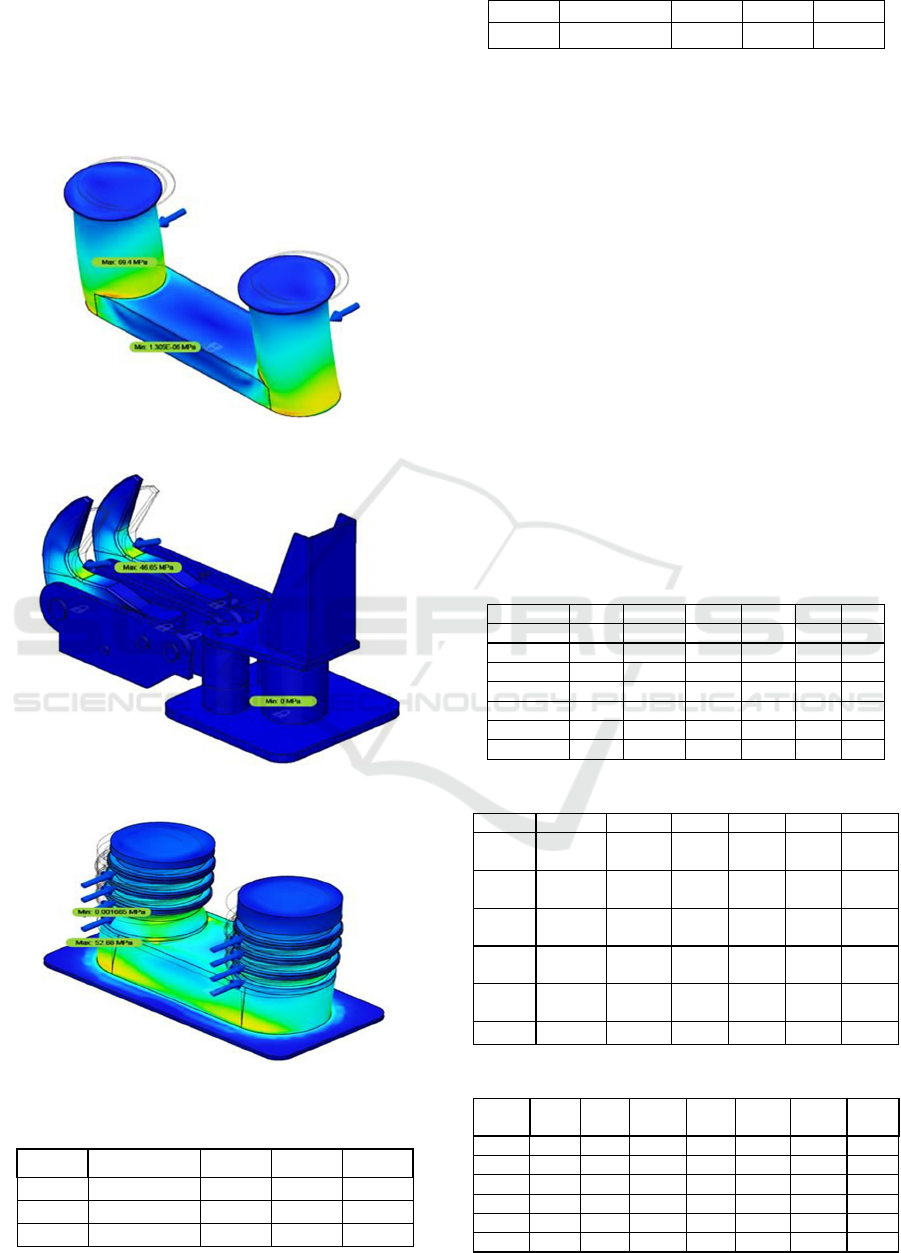
In Fig. 2, the bollard structure stress analysis of
option 2 shows a higher level than that of option 1,
which is 69.40 MPa. In Fig. 3, the result of the stress
analysis for the quick release hook type is 46.65 MPa.
The maximum stress on the structure of the winch
bollard is 52.68 MPa, shown in Fig. 4.
Figure 3: Stress analysis of alternative 2.
Figure 4: Stress analysis of alternative 3.
Figure 5: Stress analysis of alternative 4.
Table 6: Comparison of structural safety analysis.
Altern Displacement Strain Stress Safety
atives (mm) (MPa) factor
1 0.1439 2.077E-04 39.15 6.002
2 0.3309 4.803E-04 69.40 4.539
3 0.0813 3.784E-04 46.65 4.437
4 0.3375 3.789E-04 52.68 5.980
Table 6 shows a comparison of the analysis
results,
including safety factors, displacement, strain,
and
stress. The design has complied with the strength
criteria of (BV, 2017) that the minimum safety factor
is
1.5.
A.
Selection of the Options
The selection of design concepts performed after
identifying shipbuilder preferences applies the
criteria of design complexity (C1), function (C2),
strength (C3), manufacturing (C4), maintenance
(C5), and price (C6). Table 4 shows a pairwise
comparison matrix that describes the relative
contribution or influence of each element to the goal
or criteria that are a level above it. Table 5 shows the
calculation of the criteria eigenvalues and tests their
consistency. Table 6 shows the calculation of the
average value for each row, hereinafter referred to as
the criteria eigenvalues. Table 7 is a sample of
alternative data with the values taken according to the
data collected.
Table 7: Weighing between the selection criteria.
Criteria C1 C2 C3 C4 C5 C6
C1 1 5 1/5 7 5 7
C2 1/5 1 1/9 1 3 1
C3 5 9 1 9 7 5
C4 1/7 1/1 1/9 1 3 1
C5 1/5 1/3 1/7 1/3 1 1/3
C6 1/7 1/1 1/5 1/1 3 1
sum 6.69
17.33
1.77 19.3 22 15.
Table 8: Normalized Criteria Matrix.
Criteria C1 C2 C3 C4 C5 C6
C1 1/
6.69
5/
17.33
0.2/
1.77
7/
19.33
5/22
7/
15.33
C2
0.2/
6.69
1/
17.33
0.11/
1.77
1/
19.33
3/22
1/
15.33
C3
5/
6.69
9/
17.33
1/
1.77
9/
19.33
7/22
5/
15.33
C4
0.14/
6.69
1/
17.33
0.11/
1.77
1/
19.33
3/22
1/
15.33
C5
0.2/
6.69
0.33/
17.33
0.14/
1.77
0.33/
19.33
1/22
0.33/
15.33
C6
0.14/6.69
1/17.33 0.2/1.77 1/19.33
3/22
1/15.33
Table 9: Criteria Eigenvalues.
Criteri
a
C1 C2 C3 C4 C5 C6
Averag
e
C1
0.15 0.29 0.11 0.36 0.23 0.46 0.27
C2
0.03 0.06 0.06 0.05 0.14 0.07 0.07
C3
0.75 0.52 0.57 0.47 0.32 0.33 0.49
C4
0.02 0.06 0.06 0.05 0.14 0.07
0.07
C5
0.03 0.02 0.08 0.02 0.05 0.02 0.04
C6
0.02 0.06 0.11 0.05 0.14 0.07 0.07
iCAST-ES 2021 - International Conference on Applied Science and Technology on Engineering Science
1302
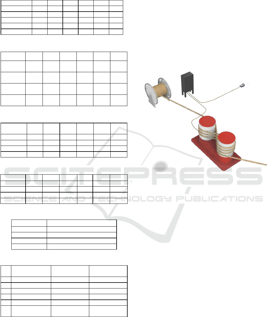
Table 10: Alternative-criteria comparison.
Alternatives C1 C2 C3 C4 C5
C6
1 80 86 98 92 86 83
2 80 83 80 89 86
83
3 89 80 95 80 80 80
4 98 89 92 86 83 98
sum 347 338 365 347 335 344
Table 11: Alternative Matrix Normalization.
Alternative
C1 C2 C3 C4 C5 C6
1
80/
347
86/
338
98/
365
92/
347
86/
335
83/
44
2
80
/
83
/
80
/
89
/
86
/
83
/
347 338 365 347 335
344
3
89
/
80
/
95
/
80
/
80
/
80
/
347 338 365 347 335
344
4
98
/
89
/
92
/
86
/
83
/
98
/
347 338 365 347 335
344
Table 12: Alternative Eigenvalues.
Alternatives
C1 C2 C3 C4 C5 C6
1 0.231 0.254 0.268 0.265 0.257 0.241
2 0.231 0.246 0.219 0.256 0.257 0.241
3 0.256 0.237 0.260 0.231 0.239
0.233
4 0.282 0.263 0.252 0.248 0.248 0.285
Table 13: Alternative-criteria eigenvalues.
Alternatives
C1 C2 C3 C4 C5 C6
1
0.061 0.017 0.132 0.017 0.009 0.018
2
0.061 0.017 0.108 0.017 0.009 0.018
3 0.068 0.016 0.128 0.015 0.009 0.017
4 0.075 0.018 0.124 0.016 0.009 0.021
Table 14: Final assessment results.
Alternatives Final result
1 0.255
2 0.229
3 0.253
4 0.263
Table 15: Comparison of Existing and New Bollard.
No Variable Existing bollard
Winch bollard
1 Material Grade A Grade AH32
2 Yiel
d
Strength 235
315
3 Tensile Strength 400 - 520 450 - 590
4 Stress 39.15 MPa 52.68 MPa
5 Safety Facto
r
6.002 5.98
6 Operational Manual
Automatic with
moto
r
Table 8 shows the calculation of the alternative matrix
normalization. Table 9 shows the calculation of the
alternative eigenvalues obtained from the
of results
dividing the criteria value into alternatives and the
number of each criterion. Table 10 present the
eigenvalues of alternative-criteria which is calculated
by multiplying the average of criteria eigenvalues
with the alternative eigenvalues for each
corresponding criterion. Table 11 shows the final of
selection result by summing the alternative-criteria
values. The eigen final result shows that the most
rational bollard is alternative 4. The winch bollard has
the highest score and rationally to be recommended
for fabrication. Table 12 presents the specification
comparison of alternative 4, the selected bollard to
alternative 1, the existing bollard installed in the
previous vessel.
Figure 6: Winch Bollard.
Winch bollard modeling is shown in Figure 6.
This
type of bollard saves space on the deck and can
perform automatic mooring operations so that it is
more effective than the standard (manual) method
currently available. The performance of this winch
bollard is that the bollard body can rotate and pull the
rope when the ship is mooring with just one person
operating equipped with speed control.
The advantages of the winch bollard are:
a.
The operation is carried out by just one person.
b.
Automatic mooring system.
c.
Easier and time-savings
d.
Optimal and safe control using the foot pedal.
e.
There is speed control.
f.
Low noise during operation.
4
CONCLUSIONS
The structure of the winch bollard have been designed
and the safety factor is 5.980 which is almost the same
level with the safety factor of the existing JIS type
bollard, 6.002. The study proves that the benefit of the
winch bollard affect the decision-maker to provide
Structural Safety and Analytic Comparison of Mooring Bollards
1303

the highest weighing to this alternative. The future
works of this research is to develep the detail design
and prototype of the winch bollard.
ACKNOWLEDGEMENTS
The authors would like to acknowledge to Politeknik
Perkapalan Negeri Surabaya for providing the
publication fund.
REFERENCES
S. R. Chao, J. Choung, C. M. Oh, and K. S. Lee,. (2010).
Ultimate load capacities of mooring bollards and hull
foundation structure. Ocean Engineering, vol. 37, pp.
770-776, 2010.
JIS (Japanese Industrial Standards), 1995. JIS-F2001,
bollards.
DIN (Deutsche Industrie Normen), 2001. DIN-82607,
double bollard.
A. C. Kuzu, O. Arslan. (2017). Analytical Comparison of
Different Mooring System. Conference of IAMU AGA,
Varna, Bulgaria.
ABS, 2004, Guide For Building and Classing Floating
Production Installations. USA: American Bureau of
Shipping.
B. Triatmojo, Hidrologi Terapan, 2010, Yogyakarta, Beta
Offset.
Brunelli, Matteo 2015. Introduction to the Analytic
Hierarchy Process. SpringerBriefs in Operations
Research. P. 83. 978-3-319-12502-2 (electronic).
10.1007/978-3-319-12502-2.
BV( Bureau Veritas), 2017. Rules for Certification of
Lifting Appliances onboard Ships and Offshore Units,
Chapter 2: Design Assessment, Section 3: Structural
Assessment.
iCAST-ES 2021 - International Conference on Applied Science and Technology on Engineering Science
1304
