
Characteristics of Flow Rate on the Performance of Pico Hydro
Turbine System as an Alternative Powerplant
Rusman
1
and Khairuddin Karim
2
1
Mechanical Engineering Department, Politeknik Negeri Samarinda, Samarinda Indonesia
2
Electrical Engineering Department, Politeknik Negeri Samarinda, Samarinda, Indonesia
Keywords: Turbine, Green Energy, Environmentally Friendly, Characteristic, Flow Rate.
Abstract: The essential functional boundaries of a streamlined pico-hydropower framework with an arrangement for
water reusing were explored. Five worked on the turbine of sprinter measurements 0.45, 0.40, 0.35, 0.30, and
0.25 m were planned, privately manufactured, and tried related to five PVC lines of measurements 0.0762,
0.0635, 0.0508, 0.0445, and 0.0381 m as penstocks. Five straight forward spouts of region proportions 1.0,
0.8, 0.6, 0.4 and 0.2 were created for every penstock width. The turbines were progressively mounted at the
foot of an overhead supply to such an extent that the powerful upward range from the power source of the
supply to the plane of the turbine shaft was 6.95 m. A 0,125 kW electric siphon was utilized to reuse the water
downstream of the turbine back to the overhead supply. The mean most extreme, what's more, least rotational
velocities of the shaft of every turbine were estimated for every penstock distance across and spout region
proportion, and the volumes of water dislodged in the repositories were too checked. This deliberate
information was utilized to process shaft force and framework volumetric stream rate for every activity.
Dimensionless stream, head and force coefficients, and explicit speed were registered, and functional
attributes were created. This standard technique by and large utilized for the examination of mathematically
comparable water-driven machines have been applied to this framework, and the outcomes got will be
priceless being developed of the framework into a straightforward, harmless to the ecosystem and tiny
decentralized force age framework that might contribute absolutely to the energy blend in Indonesian. The
chance of scaling the framework to oblige giant turbine and penstock measurements, and thus higher limit
alternators exist and is an objective for future turns of events.
1 INTRODUCTION
Although energy plays a significant role in a country's
economic development, access to power is minimal
in many developing countries due to a mix of factors
(Yah, 2017). Many functional energy supply systems
operate below-installed capacity in Indonesia and are
often vulnerable to limitations due to human and
natural causes. In addition, many of the designs are
large, centralized, and utilize energy resources that
have few adverse impacts on the environment. In
addition, some of the energy sources used are
depleting, so their sustainability is not guaranteed
(Edomah, 2016). Exploring and transporting new
deposits also adds to adverse environmental effects
such as oil spills while increasing friction in the host
community (Olusegum, 2010).
As a result, there is increasing interest and
demand for renewable energy sources and more
intelligent, smaller, and more decentralized energy
systems that will make more efficient use of these
renewable and conventional sources. This system
gives end users more control, which creates a greater
sense of responsibility regarding system maintenance
and security, especially with saboteur activities
common to various motivations (Bala, 2013). Also,
developing systems that generate the required power
at or close to the point of application can reduce
attacks on supply structures, especially with
increasing regional unrest in a developing country
like Indonesia. Such a system does not require
maintenance and protection of the supply structure.
Hydroelectric power plants have many advantages
over renewable energy sources from solar power
(Ribal, 2017).
Rusman, . and Karim, K.
Characteristics of Flow Rate on the Performance of Pico Hydro Turbine System as an Alternative Powerplant.
DOI: 10.5220/0010960100003260
In Proceedings of the 4th International Conference on Applied Science and Technology on Engineering Science (iCAST-ES 2021), pages 1097-1102
ISBN: 978-989-758-615-6; ISSN: 2975-8246
Copyright
c
2023 by SCITEPRESS – Science and Technology Publications, Lda. Under CC license (CC BY-NC-ND 4.0)
1097

2 MATERIAL AND METHOD
PVC pressure lines of breadths 0.0762, 0.0635,
0.0508, 0.0445 and 0.0381 m were chosen as
penstocks. As indicated by (Kunwor, 2012) and
(ESHA.Small Hydropower, 2018 ). PVC is lighter,
has better grating qualities, and is less expensive than
steel, separated from the abstract factor of being all
the more promptly accessible in the necessary sizes.
Their pressing factor qualities are comparable. The
related frictional misfortunes were assessed utilizing
the conditions proposed by (Muchira, 2011) for lines
of breadth more noteworthy than 5 cm and stream
speed under three m/s. A normal worth of C = 137.5
was utilized in this examination since it lies between
135 furthermore, 140 for plastic lines. The choppiness
misfortunes (Ht) were assessed with values for the
coefficients K for pipe section, door valve, and 90º
elbow got from (Yan, 2012) as 0.5, 0.25, and 0.9
individually. For the change in penstock
measurements, K qualities were gotten utilizing the
condition given by (Muchira, 2011). The K qualities
for the decrease of penstock from 0.0762 to 0.0635 m,
0.0635 to 0.0508 m, 0.0508 to 0.0445 m, and 0.0445
to 0.0381 m were then registered. Ht esteems were
then figured with just the valve, elbow, and section
coefficients applied to the biggest measurement
penstock. The compression coefficients were then
progressively added as the penstock sizes were
diminished. The net head accessible was then
processed. The planning technique for a solitary spout
Pelton turbine looking like a propeller turbine was
taken on. This is because a propeller turbine takes into
consideration the generators to be straightforwardly
determined consequently staying away from
transmissions and the chaperon misfortunes.
Likewise, the sprinters had a somewhat lower number
of fixed cutting edges, in this manner improving the
fabricating cycle and lessening the potential for
conflicting sharp edge development and direction.
Besides, the Pelton turbine can be mounted upward or
evenly (Ingram, 2009). An abasic Angular shape
sharp edge with about 60º included point was taken
on. The methodology introduced was utilized in this
work to acquire the base turbine sprinter widths
which were then, at that point scaled upwards to
improve manufacturability, what's more, application
for the investigation. The upsides of the framework
stream rate processed were subbed into the
articulations for the turbine boundaries given by
RETScreen. The particular speed of the turbine was
processed utilizing several spouts = 1 (for
straightforwardness and simplicity of fabricating).
This was utilized to process the turbine sprinter
measurement, DT in meters. Five (5) various upsides
of DT were gotten relating to the five penstock sizes
chose which were then scaled upwards. The scaled
upsides of DT utilized for this work were 0.25,
0.30,0.35, 0.40, and 0.45 m. The center point distance
across and subsequently, edge tallness or cup length
was found utilizing an articulation given by
(ESHA.Small Hydropower, 2018 ). Just as the edge
stature. The number of edges was chosen from a
diagram of boundaries for measuring turbines by
(Bala, 2013) to be 6. The center point and cups were
projected from acrylic in the wake of doing the actual
starter tests, what're more, arrangements to the sizes
acquired. The cups were entirely welded to the center
point utilizing gas welding. Two roundabout spines
made of a 2 mm steel sheet to work with the coupling
of a steel shaft of 20 mm distance across the center
are welded to the post in the wake of going the beam
through an opening in it. The spine has arrangements
for three (3) M14 screws and nuts that are equitably
situated along an advantageous circumferential plane
so the center point with the cups is clasped opposite
the shaft. An average proportion of spine breadth (Df)
to center measurement (Dh) of 0.75 was utilized for
the five turbines. Fig. 1 shows the gathered turbine
sprinter. The gathered turbine was mounted in a
packaging made of 4 mm sheet steel and remotely
built up having an annulus or stream region (A),
which fulfills the base condition for freedom of about
0.03 m. Figure 2 shows a gathered turbine. Proper
orientation and seals were chosen to mount the
turbine with free turn and forestall spillages. The
packaging cover was gotten in position utilizing M13
and M14 fasteners and nuts. The help of the turbine
was made of a blend of 5 mm youchannel and 4 mm
point iron with arrangements for four M20
establishment bolts. The leave conduit was
rectangular cross-area and tightened to a 76.2 mm
measurement inside the strung barrel-shaped
connector. The line was advantageously skewed in
request to improve the release of water from the
turbine. Fig. 1 shows a detonated perspective on the
turbine. The spouts were created utilizing a 1 mm
thick steel sheet. The advancement of each was cut
out of the sheet metal which was then, at that point,
suitably collapsed and welded utilizing gas welding
on account of the light check of the metal. The spouts
had a mean stature of 50 cm. Figure 2 shows every
one of the spouts utilized for the examination, each
set of 5 including taps of region proportions 1.0 to 0.2.
Fig. 1 shows the complete setup for the study, while
Fig. 2 shows a broadened perspective on the parts on
the ground. It has two repositories, one mounted
overhead, and the other underground. The course of
iCAST-ES 2021 - International Conference on Applied Science and Technology on Engineering Science
1098

action was to such an extent that the overhead supply
conveys water to the turbine through the penstock.
Five spouts of the comparable length of around 50 cm
were created for every penstock measurement with
region proportions of 1.0, 0.8, 0.6, 0.4, and 0.2 to
work with stream speed increase at the exit of the
penstock. Water from the spouts encroaches on the
turbine's sharp edges when the outlet valve of the
overhead supply is opened. The entire turbine
gathering is mounted on a level plane with the water
outlet port advantageously slanted with the end goal
that streams from the turbine packaging are
improved. The turbine releases water to the ground
supply. The water is then re-flowed to the overhead
Supply by a 0,125 kW Touch Model electric siphon.
The siphon has an evaluated stream pace of 3.0 –
10.8m3/h (0.833 – 3.0 x 10⁻³ m3 /s) with the most
outstanding and least heads of 29 m and 17 m
separately Furthermore, 220 – 240V, 7.1A. For this
examination, the head, H ≈ 6.95 m. The test
framework release was then, at that point still up in
the air for every penstock size by timing the release
of water from the overhead supply. The rotational
speed of the shaft of the turbine (N) was estimated
utilizing the DT-2268 and DT- 2858 Contact Type
Advanced Tachometer for each Penstock distance
across and spout setup. The tachometers had a 5-digit,
10 mm LCD show With an estimation scope of 2.5 –
99,999 Rpm. The goal is 1 Rpm more than 1000 Rpm
with the precision of ± 0.05% + 1 Rpm and
photograph Distinguishing distance of up to 300 mm.
The tachometers have the memory ability to appear
the last worth, most extreme price, and least Esteem,
and a regular examining season of 1 second. The
estimations were completed without coupling the
alternator to the turbine (no-heap Tests). The rotor of
the tachometer was squeezed daintily into a visually
impaired opening on the turning shaft in Request to
gauge the rotational speed. This was rehashed a few
times relying upon the term for a specific estimation
which was restricted by the water level in the supply
on the Ground. During this period, the most extreme
and least rotational speed was noticed and Recorded.
An average length of about 4.24 minutes/estimation
was utilized all through with the base and most
extreme qualities being 1.73Also, 6.75 minutes. The
entire method was Completed for every one of the
five turbines. The qualities of N were djusted for
misfortunes forced by the arrangement for releasing
water into the repository on the ground by applying a
factor of Hd/H, where Hd = the stature of the
conveyance port above The plain of the turbine shaft
and H = head. For the four more modest penstock
measurements, the qualities of N were additionally
adjusted because the conveyance of the line to the
ground repository was not decreased to Match their
more modest measures. A factor of Dp/Dd, where Dd
= size of the conveyance line and Dp = width of the
penstock. The water levels in the two repositories
were checked while utilizing a plunge stick alongside
an estimating tape, and They were used to acquire the
volume of water released. The volumetric stream
rates were then figured. The liquid force (Pf)
accessible for every activity was calculated utilizing
the relationship given by (Yan, 2012) and (Muchira,
2011). The shaft force, Ps, and effectiveness of the
framework were figured from the first standards
utilizing conditions given by something similar
creator.
Figure1: A Turbine Runner Assembly For The System.
For this study, the mean values of flow rate and
net head for the no-load test, as presented in Table 1,
are plotted in Fig. 3. The characteristic curve is
parabolic, with an R
2
value of 0.9697. The trend is as
obtained in a previous study (Ramos, 2012). It has the
following expression given in equation 1:
H
n,avg
= - 27132Q
avg
2
+ 740.6Q
avg
+ 1.5363 (1)
where H
n,avg
= mean system net head (m) and Q
avg
=
mean system flow rate (m
3
/ s). This expression can be
instrumental in obtaining an initial design for
increasing the flow rate for further system
development for a given value of H
n, avg
.
Based on the dimensional analysis results of the
hydraulic turbine parameters, four coefficients were
calculated to summarize and generalize its
performance. The coefficients are the coefficients of
the head, flow, and power as well as specific speed.
Characteristics of Flow Rate on the Performance of Pico Hydro Turbine System as an Alternative Powerplant
1099
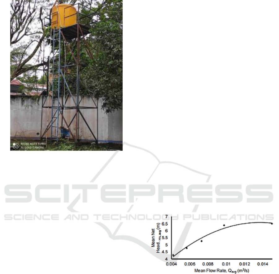
Figure 2: The Pico-Hydropower System.
They are calculated using equations 2 to 5. This
formulation will be beneficial, especially regarding
upgrading the system to produce higher power
(Ingram, 2009). They will be invaluable for the initial
design data and are the essential hope for reaching
this system in its final application form.
They can be calculated using the expressions given
below.
Flow coefficient, K
Q
= Q/ND
3
(2)
Head coefficient, K
H
= gH/N
2
D
2
(3)
Power coefficient, K
P
= P/ρN
3
D
5
(4)
Specific speed, K
S
= K
P
1/2
/K
H
5/4
(5)
3 RESULTS AND DISCUSSION
For this examination, the mean upsides of the stream
rate and the net head for the no-heap tests as
introduced in Table 1 were plotted in Fig. 3. The
trademark bend was illustrative, with R2 worth of
0.9697. The pattern is as-is reachable in past
investigations (Yan, 2012). It has the accompanying
articulation given in condition 8:
Hn,avg = - 27132Qavg2 + 740.6Qavg + 1.5363 (6)
where Hn,avg = mean framework net head (m) and
Qavg = mean framework stream rate (m3/s). This
articulation can be extremely helpful in getting an
underlying plan for increasing stream rate for
additional improvements of the framework for given
upsides of Hn,avg (Yan, 2012). Four coefficients
were processed, to sum up, and sum up their
exhibition, given aftereffects of dimensionless
examination of water-powered turbine boundaries.
The coefficients were ahead, stream, and force
coefficients just as the particular speed. They were
figured utilizing Conditions 4 to 7. These details will
be precious, particularly regarding likely
arrangements to increase the framework to produce
higher force (Muchira,2011). They will be priceless
for starting plan information and are critical to
accomplishing this framework in its possible
application structure. The processed upsides of the
coefficients are displayed in Table 1. Fig. 3 relates the
mean head coefficient (KH) to the mean stream
coefficient (KQ). The trademark bend is illustrative
for this work, with R2 worth 0.9939, and the
articulation is given in condition 6.
KH = 1765.2KQ2 – 1.6098KQ + 0.0027 (7)
Fig. 3 shows the comparing bend for the connection
between the mean force coefficient and the stream
coefficient, which has an illustrative pattern with R2
worth of 0.9982. The articulation got is displayed in
condition 7.
KP = 3.4689KQ2 – 0.0019KQ + 1 x 10⁻⁶ (8)
Figure 3: Mean Net Head and Flow Rate Characteristic for
The System.
The coefficients establish many execution qualities
addressing the entire group of five turbines created
for this work. They are indistinguishable for all of
them as long as boundaries; for example, Mach
number, Reynolds' number, and relative surface
unpleasantness of the line dividers are very similar or
can be expected to be consistent. This supposition
holds for this work. Applying comparability laws and
given the presumptions over, these coefficients can be
utilized to anticipate the presentation of one more
comparable turbine with a more modest or bigger
iCAST-ES 2021 - International Conference on Applied Science and Technology on Engineering Science
1100

Table 1: Dimensionless coefficients for turbines with
penstocks of diameter 0,0508 m.
sprinter distance across running at a given speed
(Muchira, 2011). As indicated by (Muchira, 2011)
and (Yan, 2012), the particular speed (Ks ) can be
gotten from condition seven by controlling KQ, KH,
and KP. The mean upsides of the figured KS from
exploratory information for every one of the groups
of five turbines are displayed in Table 1. They all
exist in the reach 1.7 < KS < 3.0. However, these
qualities are tiny contrasted with the scope of 10 to 35
revealed by (Ingram, 2009) and (ESHA.Small
Hydropower, 2018 ) for one-stream Pelton turbines,
they are near one another, fortifying a previous idea
during the time spent the bigger extent of the
examination that the distinction between the sprinter
measurements was not huge enough to affect upon
their exhibitions fundamentally.
4 CONCLUSION
Up until now, the discoveries in this work on the
streamlined pico-hydro framework show that it likely
exists for it to contribute emphatically towards
improving the energy mash in Indonesia and other
agricultural nations as a unit that will work without
reliance on abnormal environmental conditions,
without antagonistic impacts on the climate and
which surrenders control to the end client. Further
advancement is anyway essential to completely
understand this potential. Its boundaries should be
appropriately controlled to accomplish a self-running
status before it can turn out to be economically
helpful. The proposals for this work are issues for the
following phase(s). Given the current discoveries and
the first desires of this examination, further
subsidizing will be looked for so the accompanying
viewpoints could be researched: (1) The conveyance
pipe from the siphon will be altered to make the
proportion of conveyance release from the supply to
be more good for framework execution; (2) The
framework will be tried with the overhead repository
situated above 7.0 m to exploit more noteworthy
head; (3) a close financial examination of this
framework with an independent sun oriented force
framework and a petroleum product fueled
framework will likewise be attempted.
REFERENCES
Yah, N.F., A.N. Oumer, and M.S. Idris, Small scale hydro-
power as a source of renewable energy in Malaysia: A
review. Renewable and Sustainable Energy
Reviews,2017. 72: p. 228-239.
Edomah N. On the path to sustainability: Key issues On
Nigeria’s sustainable energy development, Energy
Reports. 2016;2:28- 34.
Olusegun HD, Adekunle AS, Ohijeagbon IO, Oladosu
OA,Ajimotokan HA. Retrofitting a hydro-power
turbine for he generation of clean electrical power.
USEP: Journal of Research Informationin Civil
Engineering.2010;7(2):61-69.
Bala EJ. Achieving renewable energy potential in Africa,
Joint WEC, AUC and APUA Workshop, Addis Ababa,
Ethiopia;2013.
Ribal A, Amir AK, Toaha S, Kusuma J,Khaeruddin K.Tidal
current energy resource assessment Around Buton
Island, Southeast Sulawesi, Indonesia. International
Journal of Renewable Energy Research. 2017;7(2).
Kunwor A. Technical specifications of micro-
hydrosystems design and its implementation:
Feasibility analysis and a sign of Lamaya Khola micro-
hydropower plant. BSc. Thesis, Arcada
Polytechnic;2012.
ESHA.Small Hydropower energy efficiency Campaign
action (SHERPA) -strategic study for the development
of small dro power (SHP) in the European Union.
European Small Hydropower Association 2008.
Available:http://www.esha.be/
Muchira MJ. Performance of a modified vehicle Drive
system in generating hydropower. A Thesis submitted
for MSc. Renewable Energy Technology, Kenyatta
University, Kenya. 2011;44.
Ho-Yan B. Design of a low head Pico hydro turbine For
rural electrification in Cameroon. Thesis Presented
toThe University of Guelph, Canada; 2012.Available
https://dspace.lib.uoguelph.ca/xMaui/handle/10214/35
52
Nozzle area Turbin Runner Head Power Coeff Flow Coeff Spesific
ratio
Dia., D
T ( m)
Coeff Kp x 10 -4
K
Q
x 10-4
speed
A1/A2
K
H x 10-3
Ks
1,0 4,20 3,43 8,28 1,77
0,8 3,83 2,68 6,90 1,68
0,6 0,45 3,11 1,74 5,97 1,82
0,4 2,89 1,31 4,33 1,71
0,2 2,71 0,69 2,97 1,57
1,0 3,45 2,78 9,02 2,20
0,8 2,78 1,87 8,00 2,31
0,6 0,40 2,54 1,65 7,07 2,30
0,4 2,35 1,07 5,60 2,05
0,2 2,09 0,82 3,51 1,80
1,0 4,55 6,57 11.59 2,15
0,8 3,97 5,43 9,81 2,19
0,6 0,35 3,43 3,66 8,25 2,33
0,4 2,25 2,52 4,52 2,21
0,2 2,00 1,08 4,05 2,11
1,0 3,57 4,77 14,99 2,70
0,8 3,07 3,09 13,55 3,20
0,6 0,30 2,86 2,13 12,89 3,41
0,4 2,54 1,64 9,23 3,01
0,2 2,08 1,23 7,65 2,70
1,0 3,86 8,79 22,12 3,04
0,8 3,23 7,82 20,67 3,05
0,6 0,25 3,19 6,45 18,76 3,20
0,4 3,13 4,75 15,21 2,91
0,2 3,02 3,01 10,54 2,48
Characteristics of Flow Rate on the Performance of Pico Hydro Turbine System as an Alternative Powerplant
1101

Ingram G. Basic concepts in Turbomachinery, Grant
Ingram and VentusPublishing ApS. 2009;17:88-
91.Available:www.bookboon.com
Ramos HM, Kenova KN, Pillet B. Stormwater storage pond
configuration for hydropower Solutions: Adaptation
and optimization.J. of Sustainable Development.
2012;5(8):27–42
iCAST-ES 2021 - International Conference on Applied Science and Technology on Engineering Science
1102
