
Synthesis and Characterization of Chitosan-Ssodium Alginate
Composite Membrance for Direct Methanol Fuel Cell (DMFC)
Application
Rif’ah Amalia, Firmansyah Adi Nugroho and Ivan Susanto
Department of Mechanical and Energy Engineering, Politeknik Elektronika Negeri Surabaya, Surabaya, Indonesia
Keywords:
Sysnthesis, Characterization, Methanol, Composite Membrane, Direct Methanol Fuel Cell.
Abstract:
Direct methanol fuel cell is one type of direct alcohol fuel cell, where methanol in liquid form
enters the
anode cell without going through reforming process. Methanol has the advantage of
being relatively
cheap and has high electrochemical activity. However, direct methanol fuel cells
have several
disadvantages, namely low efficiency (about 60%), slow methanol oxidation reaction
rate, the occurrence
of methanol cross over and also the price of the membrane used as an
electrolyte membrane in direct
methanol fuel cells. The procedure in this research are composite
membrane fabrication; characterization
and performance composite membrane are membrane
functional group analysis; morphology of
membrane analysis; density of membrane measurement;
methanol permeability measurement; swelling
membrane. The result from this research are based
on FTIR analysis, The entire membrane has amino and
carboxylic acid groups that are bonded to
each other and have hydrogen bonds; based on SEM analysis,
chitosan: sodium alginate membrane
has good pore performance; the density of the membrane increases as
the composition of sodium
alginate increases. The highest of membrane density is 1.3676 g/mL at 5:2
w/w; there is no
methanol crossover so that the membrane can answer the problems of conventional
Nafion®
membranes; Swelling methanol at 5:1 and 5:2 w/w have the same swelling value, which is 10;
Composite membrane from chitosan – sodium alginate can be used as as a substitute for the nafion
membrane
in DMFC.
1
INTRODUCTION
The increase in population and industrial growth
contributes to the increasing demand and demand for
energy. On the other hand, the availability of energy
sourced from fossil fuels such as coal, oil and natural
gas used in conventional power plants is decreasing
from time to time. This is an important challenge and
problem that will be faced by the world. New
renewable energy sources will answer energy
challenges and problems in order to meet future
energy needs. New renewable energy sources that can
be developed include wind, geothermal, biomass,
solar, tidal, hydropower, waves, hydrogen and fuel
cell energy.
Fuel cell is one of the promising power plants
because it has high efficiency, clean energy and low
environmental impact. The fuel cell system is
designed to consume hydrogen and oxygen directly
and produce products in the form of water, heat and
electricity. There is without fuel combustion from a
furnace or boiler turned to electrical energy, so it
cleanest and potential energy.
Fuel cell is an electrochemical cell that converts
the chemical energy in hydrogen and oxygen fuels
into electrical energy directly through a redox
reaction. Fuel cell have two electrodes, anode as
negative electrode and cathode as positive electrode.
Fuel such as hydrogen is placed at the anode cell and
oxygen at the cathode cell. The catalyst in the anode
cell releases hydrogen molecules into protons and
electrons. Electrons pass through an external circuit
to generate electricity, while protons migrate through
the electrolyte to the cathode, where protons react
with oxygen and electrons, producing heat and water.
The overall reaction have been done in the fuel cell in
following:
Anode
: H
2
→ 2H
+
+ 2e
-
Cathode
: O
2
+ 4H
+
+ 4e
-
→2H
2
O
1054
Amalia, R., Nugroho, F. and Susanto, I.
Synthesis and Characterization of Chitosan-Ssodium Alginate Composite Membrance for Direct Methanol Fuel Cell (DMFC) Application.
DOI: 10.5220/0010958900003260
In Proceedings of the 4th International Conference on Applied Science and Technology on Engineering Science (iCAST-ES 2021), pages 1054-1062
ISBN: 978-989-758-615-6; ISSN: 2975-8246
Copyright
c
2023 by SCITEPRESS – Science and Technology Publications, Lda. Under CC license (CC BY-NC-ND 4.0)
General reaction : 2H
2
+ O
2
→ 2H
2
O
Fuel cells can be applied portable in consumer
electronics, battery chargers, miniature toys, kits, and
gadgets; transportation application on auxiliary
power units, marine propulsion, stationary
application in distributed power generation,
combined heat and power, combined cooling, heat
and power, back up power supply, remote area power
supply.
Fuel cells can be classified based on operating
conditions, such as pressure, temperature, type of
electrode, catalyst, interconnection, and type of
electrolyte used. Based on the type of electrolyte, fuel
cells can be classified as follows (1) solid oxide fuel
cell with ceramic electrolyte; (2) carbonate fuel cell;
(3) proton exchange membrane fuel cell with its
electrolyte consisting of proton membrane; (4)
phosphoric acid fuel cell; (5) alkaline fuel cell with
alkaline electrolyte solution such as potassium
hydroxide, sodium hydroxide. The following details
the differences types of fuel cell:
Table 1: Types of Fuel Cell.
Different PEMF
C
AFC PAFC MCF
C
SOF
C
Electroly Hydrat Mobiliz Immobi Immo Perov
te
ed ed or lized bilize skites
Polyme Immobi Liquid d (Cera
ric Ion lized Phosph Liqui mics)
Exchan Potassi oric d
ge um Acid in Molte
Membr Hydrox SiC n
anes
ide in Carb
asbesto onate
s in
matrix
LiAl
O
2
Electrode
s
Carbon Transiti
on
metals
Carbon Nicke
l and
Nicke
l
Oxid
e
Perov
skite
and
perov
skite /
metal
cerme
t
Catalyst
Platinu
m
Platinu
m
Platinu
m
Electr
ode
mater
ial
Electr
ode
mater
ial
Interconn
ect
Carbon
or
metal
Metal Graphit
e
Stainl
ess
steel
or
Nicke
l,
ceram
Nicke
l
ic, or
steel
Operatin 40 – 80 65°C – 205 °C 650 600-
g °C 220 °C °C 1000
Temperat
°C
ure
Charge
Carrier
H
+
OH
-
H
+
CO
-
3
O
-
External
Reformer
for
hydrocar
bon
fuels
Yes Yes Yes
No,
for
some
fuels
No,
for
some
fuels
and
cell
desig
ns
External
shift
conversio
n
of CO to
hydrogen
Yes,
plus
purifica
tion to
remove
trace
CO
Yes,
plus
purifica
tion to
remove
CO
and
CO
2
Yes No No
Prime
Cell
Compone
nts
Carbon
-based
Carbon
-based
Graphit
e-based
Stainl
ess-
based
Cera
mic
Product
Water
Manage
ment
Evapor
ative
Evapor
ative
Evapor
ative
Gase
ous
Produ
ct
Gase
ous
Produ
ct
Product
Heat
Manage
ment
Process
Gas +
Liquid
Coolin
g
Mediu
m
Process
Gas +
Electrol
yte
Circula
tion
Process
Gas +
Liquid
cooling
mediu
m or
steam
generat
ion
Intern
al
Refor
ming
+
Proce
ss
Gas
Intern
al
Refor
ming
+
Proce
ss
Gas
Based on the type of electrolyte dan operation
temperature, fuel cell can be classified as follow : at
the high temperature fuell cell are molten carbonate
fuel cell and solid oxide fuel cell, and at the low
temperature are phosphoric acid fuel cell, polymer
electrolyte membrane fuel cell, alkaline fuel cell and
Synthesis and Characterization of Chitosan-Ssodium Alginate Composite Membrance for Direct Methanol Fuel Cell (DMFC) Application
1055

direct methanol fuel cell.
Direct methanol fuel cell is one type of direct
alcohol
fuel cell, where methanol in liquid form
enters the anode cell without going through
reforming process.
Direct methanol fuel cells are
widely applied in cell
phones, vehicles, laptops,
cameras, home appliances.
Methanol has the
advantage of being relatively cheap
and has high
electrochemical activity. However,
direct methanol
fuel cells have several disadvantages,
namely low
efficiency (about 60%), slow methanol
oxidation
reaction rate, the occurrence of methanol
cross
over and also the price of the membrane used as
an
electrolyte membrane in direct methanol fuel cells.
Nafion is a membrane that has a high proton
conductivity value, strong chemical stability and has
high mechanical strength. However, the Nafion
membrane can cause methanol cross over in direct
methanol fuel cells and cause environmental
pollution.
Nur Rokhati fabricated a chitosan – alginate
composite membrane for use in DMFC. The
fabricated membrane was then characterized. The
film characterization carried out included tests of:
permeability, degree of swelling, mechanics,
morphology (by SEM), and surface chemical
structure (by FTIR). The results showed that the
alginate film had a higher permeability and swelling
degree than the chitosan film. Both chitosan and
alginate give the phenomenon that the greater the
concentration of the solution, the smaller the
permeability value and the degree of swelling, with
the degree of swelling to water being the largest
followed by technical methanol (± 95%) and the
smallest being methanol PA (> 99, 9%). The
mechanical strength of chitosan film is greater than
that of alginate film. The alginate/chitosan composite
film made by layer by layer method provides better
characteristics than the composite film made by
mixing alginate solution and chitosan solution.
Romadhoni Anto conducted research on chitosan
and
sodium alginate composites. Composite
membranes
were produced with various
concentrations of
chitosan-sodium alginate. The
composites were
characterized by scanning electron
microscopy
(SEM), Fourier transform infrared
spectrophotometer
(FTIR). The FTIR spectrum
shows the NH3C group
at 1637.29 cm
-1
and the
COO group is symmetrical at 1253.68 cm
-1
which
shows the interaction between
chitosan and sodium
alginate. SEM micrographs
showed that the
composite membrane was non-
porous. The 3:5
chitosan-sodium alginate composite
membrane has
the highest proton conductivity is 9.594 × 10
-7
S/cm.
Based on the results of this study,
the chitosan-
sodium alginate composite membrane
can be
applied properly in the Direct Methanol Fuel
Cell
system.
Riki Siswanto conducted a research by
making a
chitosan-alginate composite membrane.
The results showed that there was an effect of
adding more
chitosan composition to the
membrane
characteristics. In physical properties,
the more
addition of chitosan composition causes
the
formation of smaller pore sizes. While the
mechanical
properties resulted in increased tensile
strength and
elongation values. The results of the
filtration test
resulted in a decrease in the flux value
to urea and an
increase in membrane rejection.
Chitosan alginate 4:1
(v/v) membrane has optimal
results and is better to be
used as a membrane
candidate in hemodialysis
applications. The pore
size formed is in the range of 29.14 – 105.1 nm.
Tensile value of chitosan:alginate membrane 4:1
(v/v) is 31.23 N/mm
2
and % elongation is 13.27%.
Then the value of the flux to urea is 0.03 ml.cm
-2
.menit
-1
and a membrane rejection is 60.87%.
(Eldin, 2017) conducted research on chitosan by
chemically cross linked it by activation with an
alginate biopolymer which has a low molecular
weight with various molar ratios. The results show
that the covalently cross linked CS/Alg-GA
membrane has low permeability with range methanol
2.179×10
-9
until 2.5×10
-10
cm
2
/s compared to nafion
membrane (1.14×10 cm
2
/s).
So, in this paper, the focus is on the use of low
cost, low methanol cross over and environmental
friendly membranes to overcome the weaknesses of
the Nafion membrane, but in terms of characteristics
and performance it has the same advantages and even
exceeds the Nafion membrane. The types of
membrane used in this study were chitosan and
alginate.
2
EXPERIMENTAL
2.1 Materials
Chitosan, sodium alginate, acetic acid glacial
(CH
3
COOH), tchloric acid, aquadest, methanol,
black platinum powder, platinum-ruthenium powder,
carbon paper, acrylic, syringe, oxygen cylinder,
printer hose, acrylic 3 and 5 mm.
iCAST-ES 2021 - International Conference on Applied Science and Technology on Engineering Science
1056

2.2 Method
2.2.1 Composite Membrane Fabrication
In this study, the variation of chitosan: sodium
alginate of 5:1, 5:2 (w/w). The process of making
chitosan – sodium alginate composite membrane
includes the following steps:
1.
Mixing chitosan: sodium alginate according
to
variation (5:1, 5:2 (w/w)) with 1% glacial
acetic
acid.
2.
Stirring using a hot plate magnetic stirrer for
30
minutes so that the solution becomes
homogeneous.
3.
Each homogeneous solution was allowed to
stand
for 1 night to wait for the entire reaction
to
become even.
4.
The solution that has been allowed to stand is
then
each added with 32% hydrochloric acid
(HCl)
with a volume of 1 mL HCl for every
100 mL of
solution volume, then stirred until
homogeneous.
After that, the two solutions
were mixed and
stirred for 1 hour using a hot
plate magnetic stirrer
and then stirred until
homogeneous. After that, the
two solutions
were mixed and stirred for 1 hour
using a hot
plate magnetic stirrer and then filtered
using
filter paper, so that the residue of the
mixture
could be eliminated.
5.
The homogeneous solution mixture was left for
1
night to remove air bubbles contained during
the
mixing process. The solution mixture is
placed in
the refrigerator so as not to spoil.
6.
The mixture that has been free of bubbles is
then
printed on the surface of the glass whose
edges
have been given foam double-sided
tape as a 2
mm thick mold barrier. Ensure that
the solution is
evenly distributed, so that the
resulting membrane
has an even thickness.
The membrane printing
process is carried out
in a room with good air
circulation without
conditioning the room
temperature and left to
dry evenly. If the
environmental conditions
support the drying
process, then the drying
can take place only in 1
night. After the mold
is dry, the membrane is
slowly removed from
the mold.
2.2.2 Characterization and Performance
Composite Membrane
a.
Membrane Functional Group Analysis.
Membrane functional groups analysis
using
Fourier transform infrared (FTIR)
spectroscopy.
b. Morphology of Membrane Analysis.
Surface
and cross-sectional morphology
transverse films
were observed using a
scanning electron
microscopy (SEM) with
10000X magnification.
c. Density of Membrane
1.
The steps for testing the density of composite
membranes can be broken down into the
following points:
2.
Cut the composite membrane with a uniform
size, which is 2 x 7 cm.
3.
Measure the empty weight of the pycnometer,
which is then recorded as W
0
.
4.
Measure the weight of the pycnometer with a
piece of composite membrane sample, which
is then recorded as W
1
.
5.
Measure the weight of the pycnometer filled
with water, and then record it as W
3
.
6.
Insert the composite membrane sample piece
into the pycnometer which has been filled with
water. In this measurement, you must first
make sure that there are no air bubbles in the
pycnometer. Then weigh the pycnometer
filled with water and the membrane which has
been confirmed that there are no air bubbles in
it
and the results are recorded as W
2
.
7.
For density data from air (ρa), take the
reference density, i.e 1.2 kg/m
3
, atau 0.0012
g/mL.
8.
Collecting water density data (ρ1) by utilizing
data on W
3
and W
0
, with the following
equation:
d.
Methanol Permeability
In this analysis, a vessel with a barrier is
required,
where a chitosan-sodium alginate
composite
membrane acts as a barrier. The
methodology is
described as follows:
1.
Prepare test vessels and samples of
fabricated chitosan – alginate composite
membranes that have been cut according
to
the size of the bulkhead of the vessel.
2.
Clamp the chitosan-alginate composite
membrane between the two sides of the
vessel and ensure that it is tight so that
no
methanol seeps out of the vessel
through the
gaps between the vessel and
the membrane
that may exist.
3.
One side of the vessel is filled with 50 mL
of
methanol, while the other side is left
Synthesis and Characterization of Chitosan-Ssodium Alginate Composite Membrance for Direct Methanol Fuel Cell (DMFC) Application
1057
empty.
After that, the vessel was
positioned upright,
with the composite
membrane as the base
from the side of
the methanol vessel.
4.
This test is carried out for one hour.
5.
Checking whether there is methanol
seeping
e.
Swelling Membrane
The swelling test requires an oven to dry the
fabricated composite membrane sample, a
balance to weigh the sample weight, a vessel as
a container to soak the sample in methanol, and
methanol. The testing methodology can be
described as follows:
1.
Each membrane is cut to the size of 5 x 2
cm.
2.
Put the sample into the oven and dried at
a
temperature of 125°C for 24 hours so that
the
water content evaporates.
3.
After the membrane is dry, weigh the
membrane using a balance to determine its
dry
weight (D).
4.
Soak the sample in methanol for 48 hours.
5.
After the immersion process is complete,
then
the surface of the sample is dried
using a
highly absorbent cloth or tissue so
that there is
no methanol remaining on the
surface of the
membrane.Setelah
permukaannya kering,
membran ditimbang
untuk mengetahui bobot
basahnya (W).
6.
The wet and dry weight data are then used
to
find the percentage of methanol
absorption
through the equation:
3
RESULT AND DISCUSSION
Membrane Functional Group Analysis
FTIR analysis was carried out to determine the
functional groups contained in the fabricated chitosan
– sodium alginate composite membrane. The FTIR
results are in the form of a spectrum that states the
functional groups contained in the sample which are
expressed by wave numbers. The classification of
specific functional groups based on the wave range
can be seen in table 2 below:
Table 2: Specific groups and wavelength ranges of FTIR.
Compound Functional
Group
Absorption Area (cm
-1
)
Alkana C-H 2850-2960, 1350-
1470
Alkena C-H 3020-3080, 675-870
C=C 1640-1680
Alkuna C-H 3300
Aromatik C-H 3000-3100, 675-870
C=C 1500-1600
Alcohol,
eter,
carboxylic
acid, eter
C-O 1080-1300
Aldehida,
keton,
C=O 1690-1760
carboxylic
acid, ester
Alcohol,
phenol
(monomer)
O-H 3610-3640
Alcohol,
phenol (bond
of H)
O-H 2000-3600 (length)
Carboxyl
ic acid
O-H 3000-3600 (length)
Amine N-H 3310-3500
C-N 1180-1360
Nitro
NO
2
1515-1560, 1345-
1386
The FTIR spectrum on the chitosan – sodium
alginate composite membrane with a variation of
the ratio 5/1 (w/w), based on Fig.1 which refers to
table 2 shows the C – N functional group (amino
acids) at wave numbers 1739.39 cm
-1
(x
1
) and group
C – O – O (carboxylic acid) on wave number
1216.77 cm
-1
(x
2
). The two spectra indicate that
there is an electrostatic interaction of the
carboxylate group of sodium alginate with the
protonated amino group of chitosan which indicates
that the composite membrane produced is
homogeneously mixed. At wavenumber 3442.52
cm
-1
, there is an OH group (x3). The presence of the
OH group is expected to increase the strength of the
intermolecular interactions of the fabricated
composite membrane, for example hydrogen bonds
between chitosan and sodium alginate.
iCAST-ES 2021 - International Conference on Applied Science and Technology on Engineering Science
1058
Figure 1: FTIR spectrum of chitosan - sodium alginate
composite membrane 5/1 (b/b).
The FTIR spectrum on the chitosan – sodium algia
composite membrane with a variation of the ratio 5/2
(w/w), based on Fig.2 which refers to table 2 shows
the C – N functional group (amino acids) at wave
numbers 1739.25 cm
-1
(x
1
) and group C – O – O
(carboxylic acid) on wavenumber 1216.77 cm
-1
(x
2
).
The two spectra indicate that there is an electrostatic
interaction of the carboxylate group of sodium
alginate with the protonated amino group of chitosan
which indicates that the composite membrane
produced is homogeneously mixed. At wavenumber
3396.74 cm
-1
, there is an OH group (x
2
). The presence
of this OH group produces a more drastic peak than
the 5/1 variation, so it is expected to increase the
strength of intermolecular interactions of the
fabricated composite membrane, for example
hydrogen bonds between chitosan and sodium
alginate.
Figure 2: FTIR spectrum of chitosan - sodium alginate
composite membrane 5/2 (b/b).
Morphology of Membrane
SEM characterization was carried out with a
magnification of 2000 times, where the results for
each variation showed a tendency for the chitosan –
sodium alginate composite membrane to have no
pores (non-porous).
Figure 3: SEM morphology on composite membrane
samples with a ratio of 5/1 (w/w) with a
magnification of
2000x.
In the variation of chitosan – sodium alginate
5/1
(w/w), it was found that there were quite a
number of pores formed on the surface of the
chitosan – sodium alginate composite membrane.
However, even though there are pores formed, the
number is not too large, so the membranes produced
from the variation in the ratio of 5/1 tend to have no
pores. This indicates that the solution of chitosan
and sodium alginate has been homogeneous. From
the morphological results, the chitosan – sodium
alginate composite membrane with a variation of
5/1 (w/w) has good potential to be applied in
DMFC.
Figure 4: SEM morphology on composite membrane
samples with a ratio of 5/2 (w/w) with a
magnification of
2000x.
The results of SEM morphology on the chitosan –
sodium alginate composite membrane variation 5/2
(w/w) showed that the number of pores formed was
decreasing. The decrease in the pores formed on the
composite membrane is due to the increased
Synthesis and Characterization of Chitosan-Ssodium Alginate Composite Membrance for Direct Methanol Fuel Cell (DMFC) Application
1059
composition of sodium alginate, thus closing the
pores that may be formed from chitosan. The decrease
in the pores formed also indicates that the chitosan
and sodium alginate solutions are mixed until
homogeneous.
From the results of the SEM analysis of the chitosan
– sodium alginate 5/2 (w/w) composite membrane, it
shows that the membrane has the potential to be used
as a replacement composite membrane in DMFC
applications, because the tendency of the presence of
pores on the membrane is only slightly.
Figs 1 and 2 show that the entire composite
membrane fabricated has the potential to be applied
to the DMFC and become an alternative choice for
the Nafion® membrane. The absence of pores formed
allows the chitosan – sodium alginate composite
membrane to be more resistant to methanol, so that
methanol crossover can be minimized.
For comparison, the SEM morphology results from
Nafion® (Dang, 2014) are listed below.
Figure 5: Nafion® membrane morphology with 1000x.
magnification.
From the morphology, it can be seen that Nafion®
211 has pores all over its surface. These pores cause
Nafion® 211 to easily undergo methanol crossover,
which has an impact on decreasing DMFC
performance because Nafion® 211 has pores that can
be occupied by methanol, and can even be passed as
a transport medium for methanol across from the
anode to the cathode.
Density of Membrane
From the results of density testing using a
pycnometer, the results are shown in table 3 below:
Table 3: Data on the weight of the pycnometer (W
0
), the
empty pycnometer and the membrane sample (W
1
), the
weight of the sample in a pycnometer filled with water
(W
2
), the weight of the pycnometer with water (W
3
) and
the density of water (ρ1).
Chitosan:
Sodium
Alginate
(w/w)
W
0
(g)
W
1
(g)
W
2
(g)
W
3
(g)
ρ
1
(g/m
L)
5:1 10,99 11,07 21,22 21,21
1,02
2
5:2 10,95 11,07 21,24 21,21
1,02
6
Where:
W
0
= Weight of the pycnometer (grams)
W
1
= Weight of pycnometer and sample (grams)
W
2
= Weight of pycnometer and sample filled with
water (grams)
W
3
= Weight of the pycnometer filled with water
(grams)
ρ
1
= Density of water (gram/mL)
The membrane density in each variation was
evaluated through the following equation:
The value of water density (ρ1) is obtained through
the following equation:
And the results of the evaluation of these
equations
can be seen in table 4. below:
Table 4: The results of the
calculation of the sample
density for each variation.
Chitosan:
Sodium
Alginate
(w/w)
ρ (g/mL)
5:1 1,167829
5:2 1,3676
The density value obtained can be seen through
the graph in Fig.6 below:
iCAST-ES 2021 - International Conference on Applied Science and Technology on Engineering Science
1060
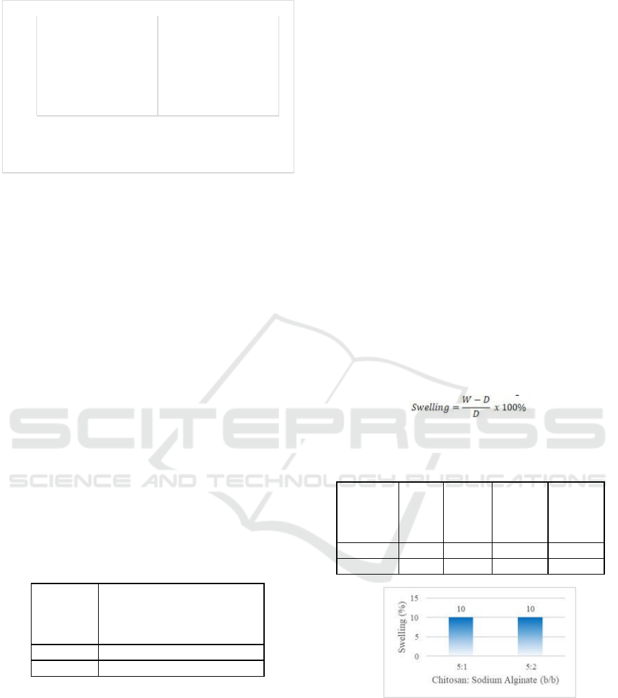
Figure 6: Comparison of the density of the chitosan –
sodium
alginate composite membrane fabricated for each
variation.
The addition of sodium alginate will improve
the
cross-linked structure of the chitosan in the gel so
that
it becomes stiffer and the gel will be stronger.
Because sodium alginate has the property of
absorbing water, the addition of sodium alginate will
decrease the breaking point of the gel, which means
that the strength of the gel will increase. The
increasing gel strength of this membrane has an
impact on increasing the density of the chitosan-
alginate composite membrane.
Because the strength of the membrane
increases,
then when viewed from the calculation
results, the
membrane density from the smallest to
the largest is
a variation of 5:1 with the result
1.167829 g/mL; 5:2
with the result 1.3676 g/mL.
Permeability of Membrane
From the membrane permeability test, the following
results were obtained:
Table 5: Membrane permeability analysis.
Chitosan:
Sodium
Alginate
(w/w)
Membrane permeability
5:1 No
5:2 No
From the test results, there is no methanol
crossover, namely the crossing of methanol to the side
of an empty vessel through or through the membrane.
The sides of the membrane in empty vessels in all
variations remained dry when wiped with a tissue,
after each test was carried out for 1 hour. This is an
indication that the chitosan – alginate composite
membrane can be used as an alternative proton
transfer membrane to replace Nafion® in DMFC,
because it is able to hold methanol, so it can solve the
problem of methanol cross over.
Methanol crossover is the event of
displacement of methanol particles from the anode
(high methanol concentration) to the cathode (low to
zero methanol concentration) and is caused because
the proton transfer membrane is unable to hold
methanol. The methanol crossover event will reduce
the performance of the DMFC because the resulting
potential difference will decrease. The underlying
reason for the methanol crossover is that there are
differences in the concentration of methanol on the
anode and cathode sides, where on the anode side the
concentration of methanol is high, and there is no
concentration of methanol at the anode. high
concentration towards the other side of lower
concentration.
Composite Membrane Swelling Analysis
The swelling test requires uniform sample pieces
for
each variation, container, digital balance, oven,
and methanol. The dry weight of the membrane was
obtained after the sample was oven-baked for 24
hours at a temperature of 125°C. Then, the wet weight
was obtained after the membrane was soaked in
methanol for 48 hours. Swelling of methanol is
obtained through the following equation:
The results obtained can be seen in table 6 below:
Table 6: dDy sample data (D) and wet sample (W).
Chitosan:
Sodium
Alginate
(w/w)
D (g) W (g) swelling %
swelling
5:1 0,1 0,11 0,1 10
5:2 0,1 0,11 0,1 10
Figure 7: Swelling of fabricated chitosan-sodium alginate
composite membrane.
From the test results, it was found that the addition
of alginate concentration could increase the
membrane's ability to adsorb methanol. This is due to
the nature of sodium alginate which only has anionic
groups (hydroxyl and carboxyl) which causes the
molecular bonds between polymer chains to be less
dense, so that there is a larger space for liquid to
1,3676
1,167829
5:1 5:2
Chitosan : Sodium Alginate (w/w)
ρ
(
gram/mL
)
Synthesis and Characterization of Chitosan-Ssodium Alginate Composite Membrance for Direct Methanol Fuel Cell (DMFC) Application
1061

occupy which makes the membrane absorption large.
While the nature of chitosan, besides having a
cationic group that can form a strong and tight film, it
also has an acetyl group which is hydrophobic (does
not absorb water). So that the absorption of chitosan
is smaller than alginate.
Thus, in this paper, data were obtained that the
more concentration of sodium alginate in the
composition of a membrane, the higher the absorption
of methanol, which is because sodium alginate has a
higher absorption capacity than chitosan.
4
CONCLUSIONS
1. Based on FTIR analysis, The entire membrane
has
amino and carboxylic acid groups that are
bonded
to each other and have hydrogen bonds.
2. Based on SEM analysis, chitosan: sodium
alginate
membrane has good pore performance.
3. The density of the membrane increases as
the
composition of sodium alginate
increases.The
highest of membrane density is
1.3676 g/mL at
5:2 w/w.
4. There is no methanol crossover so that the
membrane can answer the problems of
conventional Nafion® membranes.
5. Swelling methanol at 5:1 and 5:2 w/w have
the
same swelling value, which is 10.
6. Composite biomembrane from chitosan –
sodium
alginate can be used as as a
substitute for the
nafion membrane in DMFC.
ACKNOWLEDGEMENTS
I am sincerely thankful to local research funding from
politeknik elektronika negeri surabaya for give me
funding to do this research.
REFERENCES
EG&G Technical Services, Inc, “Fuel Cell Handbook”,
Seventh Edition, U.S. Department of Energy Office of
Fossil Energy National Energy Technology Laboratory,
November 2004.
Peighambardoust, Seyed Jamaleddin & Rowshanzamir,
Soosan & Amjadi, M.. (2010). Review of the proton
exchange membranes for fuel cell applications.
International Journal of Hydrogen Energy. 35. 9349-
9384. 10.1016/j.ijhydene.2010.05.017.
Omar Z. Sharaf, Mehmet F. Orhan, An overview of fuel cell
technology: Fundamentals and applications,
Renewable and Sustainable Energy Reviews, Volume
32, 2014, Pages 810-853,ISSN 1364-0321,
https://doi.org/10.1016/j.rser.2014.01.012.
Shaari, Norazuwana & Kamarudin, S.K.. (2017).
Characterization studies of sodium alginate/sulfonated
graphene oxide based polymer electrolyte membrane
for direct methanol fuel cell. Malaysian Journal of
Analytical Science. 21. 113-118. 10.17576/mjas-2017-
2101-13.
N. Shaari, S.K. Kamarudin, Sodium alginate/alumina
composite biomembrane preparation and performance
in DMFC application, Polymer Testing, Volume 81,
2020, 106183,
ISSN
0142-9418,
https://doi.org/10.1016/j.polymertesting.2019.106183.
B.C. Ong, S.K. Kamarudin, S. Basri, Direct liquid fuel
cells: A review, International Journal of Hydrogen
Energy, Volume 42, Issue 15, 2017, Pages 10142-
10157, ISSN 0360-
3199, https://doi.org/10.1016/j.ijhydene.2017.01.117.
N. Rokhati, B. Pramudono, N. Widiasa, and H. Susanto,
"KARAKTERISASI FILM KOMPOSIT ALGINAT
DAN KITOSAN," Reaktor, vol. 14, no. 2, pp. 158-164,
Oct. 2012. https://doi.org/10.14710/reaktor.14.2.158-
164
Romadhoni Anto, Membran Komposit Kitosan-Natrium
Alginat untuk Aplikasi Direct Methanol Fuel Cell.
Bogor : Institut Pertanian Bogor, 2013.
Riki Siswanto, Jan Ady, Djoni Izak R., Sintesis dan
Karakterisasi Biokomposit Kitosan-Alginat Sebagai
Kandidat Membran pada Aplikasi Hemodialisa,
Surabaya : Universitas Airlangga.
Mohy Eldin, Mohamed & Hashem, A. & Tamer, Tamer &
Omer, Ahmed & Youssef, Mohamed Elsayed & Sabet,
Maysa. (2017). Development of Cross linked
Chitosan/Alginate Polyelectrolyte Proton Exchanger
Membranes for Fuel Cell Applications. International
journal of electrochemical science. 12. 3840 – 3858.
Dang, Q. K., Henkensmeier, D., Krishnan, N. N., Jang, J.
H., Kim, H. J., Nam, S. W., & Lim, T. H. (2014). Nafion
membranes with a porous surface. Journal of membrane
science, 460, 199-205.
iCAST-ES 2021 - International Conference on Applied Science and Technology on Engineering Science
1062
