
Performance of TEC Cooler Box using Water Cooling and Coolant
Luh Putu Ike Midiani
1a
, I Wayan Adi Subagia
1b
, Made Ery Arsana
1c
,
Augus Sahada Permana Putra
2
, Kadek Suata
2
and Okky Dwiyon Prasetyo
2
1
Bali State Polytechnic, Kampus Bukit Jimbaran, Badung, Bali 80361, Indonesia
2
Student of Refrigeration and Air Conditioning Engineering Study Program, Bali State Polytechnic,
Kampus Bukit, Jimbaran, Badung, Bali 80361, Indonesia
Keywords
:
Cooler Box, TEC, Performance, Water, Coolant.
Abstract
:
Research on cooler boxes using thermoelectrics has been widely carried out because of the advantages of
these coolers which are easy to carry and environmentally friendly. The cooler box in this study measures 750
x 400 x 400 mm, using two thermoelectrics measuring 4 x 4 mm. The cooler box material is polyurethane,
aluminum foil and plywood on the outside. The hot side of this cooler does not use fins and fans, but utilizes
water cooling and coolant. Data collection is carried out to find the performance of the cooler box. The
measurement data is the thermoelectric cold and hot side temperature data, the inside of the cooler box, the
load and the environment. The performance of the water cooler and coolant will be compared to the
performance of the cooler with air cooling. The room temperature that can be achieved by the cooler when
using water and coolant as a cooler is 21.5°C and 19.9°C, respectively. And their respective performances are
0.41 and 0.31 for water and coolant.
1
INTRODUCTION
Research on thermoelectric coolers (TECs) is
growing rapidly to date, because TECs are a
promising future in other refrigeration applications.
TEC is the most desirable alternative cooling
technology and is possible to be developed because it
is able to control temperature precisely in various
applications and is able to overcome problems in size,
weight, performance, noise and environment. TEC
has the advantages of small size, silent operation,
limited maintenance requirements, long life, no use of
flammable or toxic refrigerants, possibility of use in
various positions and flexibility of use through
optimized control (Patel, 2016), (Atta, 2018) and
(Enescu, 2018).
TEC applications have been applied in various
fields such as electronic cooling, laser diodes,
superconducting systems, food industry, medical
equipment, military, biotechnology,
telecommunications and HVAC for specific targets.
______________________________________________________
a
https://orcid.org/0000-0002-2256-6035
b
https://orcid.org/0000-0001-9261-3549
c
https://orcid.org/0000-0002-6647-6621
For cooling small volumes of applications TEC is an
alternative, where cooling requirements are not too
high and low COP is not a real disadvantage.
Commonly, the hot side of thermoelectric cooled
by fan, in this study the thermoelectric hot side cooled
by water and coolant. The purpose of this research is
to explain the design of thermoelectric based cooler
box, to get thermal performance and effectiveness.
2
METHODOLOGY
2.1 Cooler Box Construction
This cooler box has dimensions 750 x 400 x 400 mm.
Cooling box material consists of polyurethane coated
aluminum foil and plywood. The thermoelectric used
is TEC1 12706 with a size of 4 x 4 mm as many as 2
pieces, with specifications as shown in Figure 1
(Hebei 2010).
The heat dissipation process uses forced
convection on the cold side of TEC, aluminum fins
and fans and water blocks to cool the hot side of TEC.
The water block will be filled with water for the first
test and then filled with coolant. The schematic
Midiani, L., Subagia, I., Arsana, M., Putra, A., Suata, K. and Prasetyo, O.
Performance of TEC Cooler Box using Water Cooling and Coolant.
DOI: 10.5220/0010958100003260
In Proceedings of the 4th International Conference on Applied Science and Technology on Engineering Science (iCAST-ES 2021), pages 1019-1022
ISBN: 978-989-758-615-6; ISSN: 2975-8246
Copyright
c
2023 by SCITEPRESS – Science and Technology Publications, Lda. Under CC license (CC BY-NC-ND 4.0)
1019
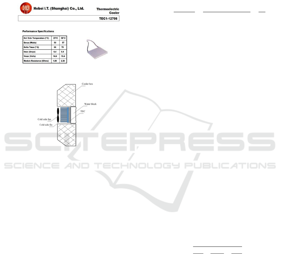
diagram of the cooler box test can be seen in Figure
2.
In this test the TEC working voltage and current are
measured using a multimeter. The temperature of
the
cooler and the room was measured with the NI
9714 data acquisition instrument and the NI 9213
module.
Figure 1: Specification of TEC1-12706.
Figure 2: Cooler box test schematic diagram.
Based on the purpose of this cooler box testing,
the first test was carried out in two test groups,
namely testing the cooler with water cooling and
coolant. The working voltage and current provided
are the same, namely 12V and 6A.
2.2 COP Analyzing
2.2.1 TEC
TEC performance can be analyzed by finding the
amount of heat absorbed on the cold side of the
thermoelectric (Qc) and the amount of heat dissipated
on the hot side of the thermoelectric. The amount of
heat absorbed and the amount of heat dissipated (Qh),
is expressed by the following formulas
(Jugsujinda,2011):
=
− 0.5
2
−
(
ℎ
−
)
(1)
ℎ
=
ℎ
+ 0.5
2
−
(
ℎ
−
)
(2)
Where α is Seebeck coefficient (VK
-1
), Tc and Th
are temperature of cold side and hot side of
thermoelectric, respectively. By comparing the
amount of heat absorbed to the difference between the
amount of heat wasted and the amount of heat
absorbed, TEC performance is expressed as follows
(Zhao, 2014):
=
−
=
(
−
)
+
=
(3)
Based on the TEC specifications, the Seebeck
coefficient (α) = 0.0425 VK
-1
and the thermal
conductivity of the thermoelectric material (K
t
) =
0.495 Wm
-1
K
-1
.
2.2.2 COP of Cooler Box
In this test the total power consumption of the
cooler box must take into account the power
consumption of the cold side fan, because the power
consumption of the cooling side fan will turn into hot.
This can be used as the main basis for determining the
optimal operating conditions of this cooler. The
calculation is as follows (Cengel, 1998) and
(Mirmanto, 2009):
=
+
+
(4)
=
∆
(5)
=
∆
(6)
=
+
(7)
where Q
l
is heat load, Q
t
is transmisi load, A is the
total heat transfer surface of cooler box, U is the
overall heat transfer coefficient. The overall heat
transfer coefficient is calculated below:
=
1
1
ℎ
+
1
+
1
ℎ
(8)
3
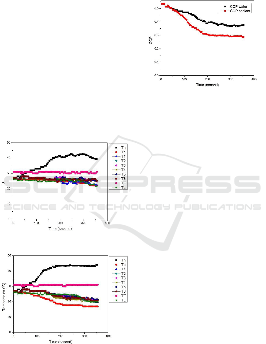
RESULT AND DISCUSSION
The cooler box temperature phenomenon is shown in
Figures 3 and 4. Temperature denoted by T
1
-T
6
, T
c
,
T
h
, T
L
, T
E
represent the temperature of cooler box,
thermoelectric cold side, thermoelectric hot side,
cooled load, and environment, respectively.
The T
L
, decreases from 0 to 355s, and then it gets
iCAST-ES 2021 - International Conference on Applied Science and Technology on Engineering Science
1020
nearly constant. The same phenomenon also found by
previous researchers that used a fan as a
thermoelectric hot side cooler (Jugsujinda, 2011) and
(Mirmanto, 2009).
Based on Figure 5, the COP obtained by the cooler
for cooling the hot side of the thermoelectric using
water and coolant are 0.38 and 0.29, respectively. The
COP obtained is still within the standard COP
thermoelectric.
After one hour, cooling water on the hot side of
the thermoelectric obtained T
c
, T
h
, T
L
and COP of 26
o
C, 31
o
C and 25.4
o
C and 0.49, respectively. Cooling
with coolant on the hot side of the thermoelectric
obtained T
c
, T
h
, T
L
and COP of 25.5
o
C, 31
o
C and
25.4
o
C and 0.48, respectively.
Finally, obtained COP 0.38 with water cooling
when T
c
, T
h
, and T
L
are 22.1
o
C, 39.3
o
C and 21.5
o
C,
respectively. The COP of cooling with coolant on the
hot side of the thermoelectric is 0.29 with T
c
, T
h
, T
L
and COP of 16.9
o
C, 44
o
C and 19.9
o
C, respectively.
Figure 3: Temperature versus time trend with water
cooling.
Figure 4: Temperature versus time trend with coolant.
Figure 5: COP for cooling by water and coolant.
4
CONCLUSIONS
TEC cooling with water and coolant has similar
temperature trend as cooling using fan. The cooling
capacity decreases with the time. The conduction
heat
transfer rate increases with the time. The total
heat
transfer rate (Q) decreases with the observation
time.
The COP of the TEC cooler box is still within
the
allowed COP TEC, which is 0.3 It is necessary
to
regulate the flow of water and coolant in order to
get
better cooling.
ACKNOWLEDGEMENTS
The author would like to acknowledgements the Bali
State Polytechnic for funding this research through
the Penelitian Unggulan Dana DIPA PNB 2021
scheme with contract number 888/PL8/PG/2021.
REFERENCES
J. Patel, M. Patel, J. Patel, and H. Modi. (2016).
Improvement in the COP of Thermoelectric
Cooler.
International journal of scientific & technology
research, vol. 5, pp. 73-76.
R. M. Atta. (2018). Thermoelectric Cooling. in
Bringing Thermoelectricity into Reality, ed:
IntechOpen, , pp. 247-267.
D. Enescu. (2018). Thermoelctric refrigeration
principle.
Patricia Aranguren P, editor.
Bringing
Thermoelectricity into Reality,
INTECH Publishing,
pp. 221-246.
I. Hebei. (2010) . Co., Ltd., Peltier Thermoelectric
Cooling Modules. Online: http://www.
hebeiltd. com.
cn.
Performance of TEC Cooler Box using Water Cooling and Coolant
1021

S. Jugsujinda, A. Vora-ud, and T. Seetawan. (2011) .
Analyzing of thermoelectric refrigerator
performance.
Procedia Engineering, vol. 8,
pp. 154-159.
D. Zhao and G. Tan. (2014) . A review of
thermoelectric
cooling: materials, modeling
and applications.
Applied Thermal
Engineering, vol. 66, pp. 15-24.
Y. A. Cengel, S. Klein, and W. Beckman. (1998) .
Heat
transfer: a practical approach vol.
141: McGraw-Hill
New York.
M. Mirmanto, S. Syahrul, and Y. Wirdan. (2019) .
Experimental performances of a
thermoelectric
cooler box with
thermoelectric position variations.
Engineering Science and Technology, an
International Journal, vol. 22, pp. 177-184.
APPENDIX
Q
c
= heat absorbed on the cold side
Q
h
= heat dissipated on the hot side
Tc = temperature of cold side thermoelectric
Th = temperature of hot side thermoelectric
iCAST-ES 2021 - International Conference on Applied Science and Technology on Engineering Science
1022
