
Auto Transfer Switch (ATS) Panel Design based on
Internet of Things (IoT)
M. Nur Faizi, Adam and Nirwan Budiyanto
Jurusan Teknik Elektro, Politeknik Negeri Bengkalis, Jl. Bathin Alam, Sungaialam, Bengkalis, Indonesia
Keywords
:
Control, Full Automatic, IoT, Energy, Main, Backup.
Abstract
:
The main source of electricity, namely PLN (Perusahaan Listrik Negara) is not always continuous in its
distribution, one day there will be a blackout which may be caused by a disturbance in the transmission
system or distribution system. To prevent this blackout, need to design an automatic control called Automatic
Transfer Switch (ATS). Automatic Transfer Switch is a switch control circuit that is fully automatic.
This tool serves to turn on and connect the backup energy source to the load automatically when the main
energy source goes out. When the main energy source returns ON, this tool will transfer the mains voltage
source to the load from the backup energy source to the main energy source again. In this research, an
Automatic Transfer Switch (ATS) panel based on the Internet of Things (IoT). In addition to
automatically
connecting energy sources, this tool can be monitored and controlled remotely using an Android
smartphone via the internet. In addition to this, this tool can also protect in the event of a power source
voltage drop that can cause damage to electronic devices. The results of the tests carried out show that the
Automatic Transfer Switch works when there is a blackout from the main energy source and transfers
the mains voltage source from the backup energy to the load with a voltage reading error of 1.0% and a
current of 1.0%. When there is a transfer of electrical energy sources, the smartphone will display text
notifications and ring notifications.
1
INTRODUCTION
Along with technological advances in the field of
electricity, the continuity of the electric power
supply is ordered. The main power supply from PLN
is not always continuous, one day there will be
blackouts which can be caused by disturbances in
the generating system, transmission system and
distribution system. Electricity can result in
disruption of service continuity, especially in the
activities of the trade, hotel, banking, hospital,
educational centers, and industrial sectors in
carrying out their production and even in residential
homes (Doso, 2013).
The control system or control is now starting to
shift to the automation of control systems, so that
human intervention in controlling is very small.
When compared to manual work, an equipment
system controlled by automation will provide
advantages in terms of efficiency, safety, and
accuracy (Indrawan et al., 2016). Automatic Transfer
Switch (ATS) is one of the control systems.
Automatic Transfer.
Switch (ATS) is an abbreviation of the word
Automatic Transfer Switch (ATS), if it is understood
based on the meaning of the word, then ATS is a
switch that works automatically, but its automatic
work is based on the possibility that if the power
source from PLN is disconnected or experiencing a
blackout, the switch will move to the source. Another
example of electricity is generators.
Several studies on the Automatic Transfer Switch
(ATS) have been carried out such as the research on
Design and Implementation of Automatic Transfer
Switch (ATS) Using Arduino Uno and Relay By
Robinzon Pakpahan from Telkom University which
can monitor the condition of the power source,
voltage, and current in the ATS system. via a web
browser. Along with the development of technology
that is all practical and online, every research on
controlling Automatic Transfer Switch (ATS)
continues to be developed,
one of which is based
on Android. This allows the
power source and the
amount of electricity to be
monitored and
controlled by an Automatic Transfer Switch (ATS)
system using a smartphone.
Therefore, to develop an
Faizi, M., Adam, . and Budiyanto, N.
Auto Transfer Switch (ATS) Panel Design based on Internet of Things (IoT).
DOI: 10.5220/0010957300003260
In Proceedings of the 4th International Conference on Applied Science and Technology on Engineering Science (iCAST-ES 2021), pages 963-968
ISBN: 978-989-758-615-6; ISSN: 2975-8246
Copyright
c
2023 by SCITEPRESS – Science and Technology Publications, Lda. Under CC license (CC BY-NC-ND 4.0)
963

Automatic Transfer Switch
(ATS) system design
system, research is carried out
with a monitoring and
control system for the Internet
of Things (IoT)-based
Automatic Transfer Switch
(ATS) module. The
advantage in this study is that
the system will be
able to monitor and control the
ATS module only
by using an android smartphone
via the internet. In
addition to this, this tool can also
protect in the event
of a power source voltage drop
which can cause
damage to electronic devices or as a
burden and
overload that can damage the device
itself.
Based on the description above, in order to
facilitate the use of the Automatic Transfer Switch
(ATS) panel, in this study a tool was created that can
monitor the Automatic Transfer Switch (ATS) panel
that can monitor and control the Automatic Transfer
Switch (ATS) panel only by using an Android
smartphone via a network. Internet. In addition to
this, this tool can also protect in the event of a
voltage
drop. Thus it is possible for an operator to
control
and monitor the power source through the
Automatic Transfer Switch (ATS), anywhere and
anytime as long as it is connected to the internet and
as load protection in the event of a power failure.
A
Auto Transfer Switch (ATS) and Auto Main
Failure (AMF)
In the previous study, it was explained about the
design of PLC-based Automatic Transfer Switch
(ATS) and Automatic Main Failure (AMF) systems.
The design to produce ATS with the controller used
is a PLC brand Telemanique SR2B201BD. The
results obtained that the transfer of the PLN power
supply to the generator power supply with a fast
response, where starting for 3 seconds, the transfer
after receiving the frequency and voltage sensor
input for 6 seconds, the transfer delay 3 seconds
(Muhammad Nur Shiha, 2011).
The PLC used is
equipped with temperature, voltage
and frequency
sensors.
In the previous study, carried out the basic
design of the Automatic Main Failure and Automatic
Transfer Switch system for the meeting room of the
71 BATAN Serpong building (Enggar et al., 2011).
This design aims
to anticipate when PLN fails to
supply electricity
(blackouts), the generator that will
replace the role
of PLN to supply electrical
resources This design
produces ATS which has a
large size with many
components used, such as a
timer relay and a lot of
contactors because it uses
a generator with a
generator power (200 kVA) so
that components that
have the appropriate capabilities
are needed.
In research (Hasaafu et al., 2012), designing
Automatic Transfer
Switch (ATS)/Automatic Main
Failure (AMF)
Based on Programmable Logic
Controller (PLC).
This design is made to make it
easier to control the
power supply in anticipating the
loss of power
supply to the load by making a backup
power supply
transfer device quickly with a PLC.
After the PLC-
based ATS (Automatic Transfer
Switch)/AMF
(Automatic Main Failure) design has
been
completed, it can be concluded that if the
electrical
energy supply from PLN is interrupted, the
electrical
energy supply will be taken over by the
generator
automatically. The process of switching
the supply
of electrical energy from PLN to the
generator takes
25 seconds which is used as a process
to prepare the
supply of electrical energy from the
generator such
as starting and heating the generator.
When the
supply of electrical energy from PLN
returns to
normal, PLN will again take over the
supply of
electrical energy to the load, while the
supply of
electrical energy from the generator will
be cut off
and the generator will be turned off.
B
Contactor
A contactor is an electromechanical component
that
can function as a connector and circuit breaker,
which can be controlled remotely the movement of
its contacts occurs because of the electromagnetic
force. Magnetic contactor is a switch that works
based on magnetism, meaning it works when there is
electromagnetic induction. Magnets function as
attractor and release contacts. The magnetic
contactor will work normally when the voltage
reaches 85% of its working voltage, when the
voltage drops the contactor will vibrate. The size of
the contactor is determined by its current capability
limit. There are two kinds of contacts on the
contactor, namely the main contact and the auxiliary
contact. Meanwhile, according to their work, the
contacts are divided into two, namely Normally
Open (NO) and Normally Closed (NC). The NO
contact is when the contactor does not get an electric
power supply, the contact is open, while when the
contactor gets an electric power supply, the contact
will be closed. While the NC contact is when the
contactor does not get an electric power supply, the
contact is closed while when the contactor gets an
electric power supply, the contact is open (Riki
Rizaldi, 2018).
iCAST-ES 2021 - International Conference on Applied Science and Technology on Engineering Science
964
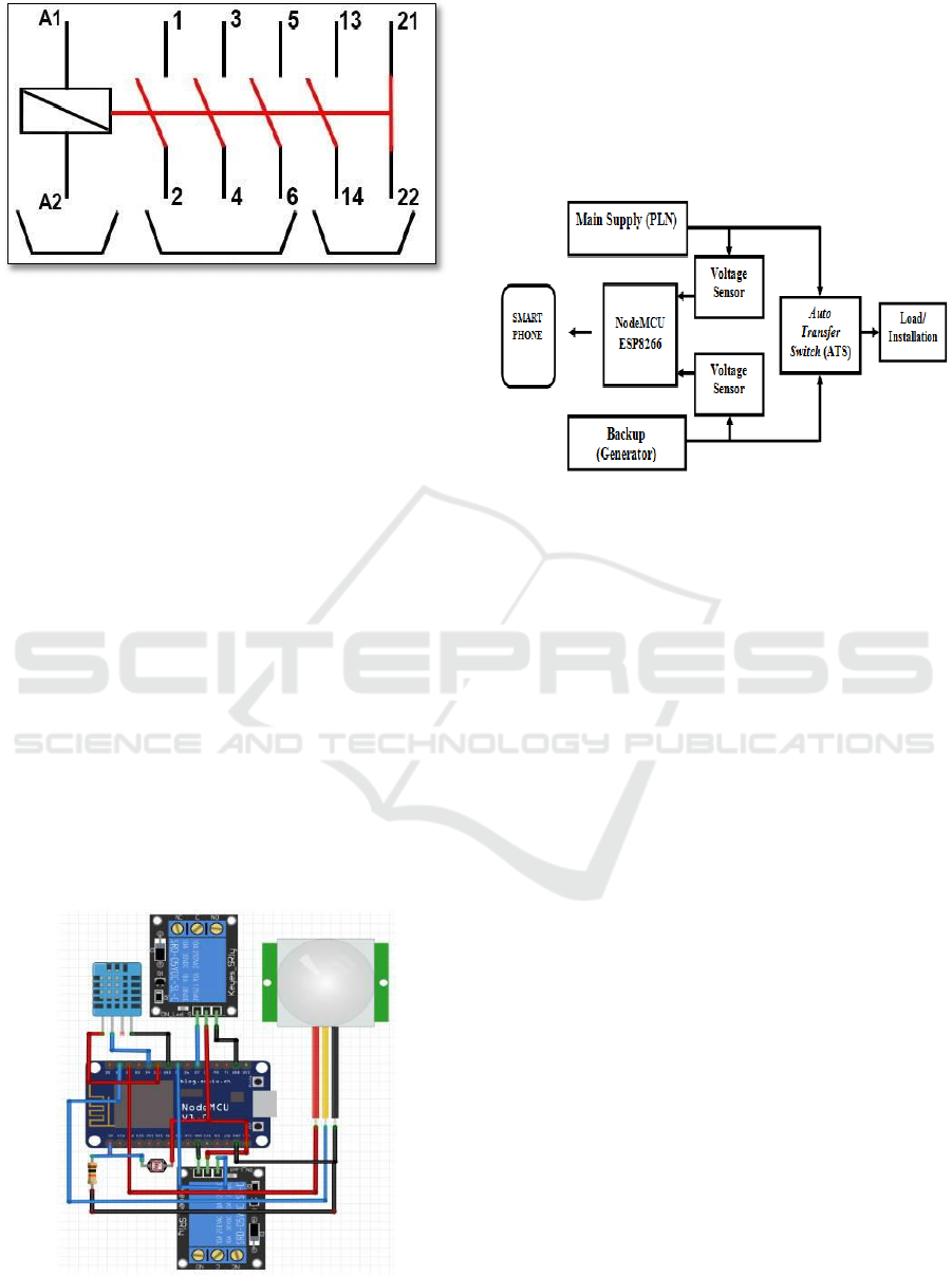
Figure 1: Contactor Circuit (Riki Rizaldi, 2018).
C
NodeMCU ESP8266
NodeMCU is an open source IoT platform.
Consists
of hardware in the form of System On Chip
ESP8266
from ESP8266 made by Esperessif
System.
NodeMCU can be analogous to an Arduino
board
connected to the ESP8622. Implement the
NodeMCU ESP8266 module for smart home.
NodeMCU is a versatile wifi module because it is
equipped with GPIO, ADC, UART and PWM. In
this study the NodeMCU ESP8266 functions as a
client and controller for fans and lights. NodeMCU
ESP8266 will receive input from sensors to control
fans and lights according to the condition of the
DHT11 and LDR sensors, send home condition data
to the server and receive data from the server to
determine whether the PIR sensor is active or not.
While on the server side, in addition to displaying
information, the server can also send notifications to
the user's e-mail. Applications are made on the
server side using the PHP programming language
and MySQL database (Mochamad Fajar Wicaksono,
2017).
Figure 2: Smart Home Circuit with NodeMCU. (Mochamad
Fajar Wicaksono, 2017).
2
METHODS AND DISCUSSION
A
System Design
The overall system block diagram design of the
Internet of Things (IoT) based Auto Transfer Switch
(ATS) panel is shown in Figure 3.
Figure 3: System Block Diagram.
From the block diagram, it can be explained that
when the main power supply is interrupted which
results in the cessation of electricity, the Auto
Transfer Switch (ATS) will work by diverting the
supply of electrical energy to a backup power supply
and vice versa, when there is no electricity supply
from PLN and restore switch to the main switch
when the mains supply is available and both supplies
can be monitored.
B
Hardware Design
The hardware or mechanic design in this
research
consists of making mechanical Auto
Transfer Switch
(ATS) panels made of iron plates or
box panels. This
Auto Transfer Switch (ATS) panel
is equipped with
a security system with relays and
fuses. This
operating system is very easy, because it
has been
arranged in such a way. Next is the design
of the
voltage sensor. This voltage sensor is made as
an
input to the NodeMCU ESP8266 module. All
output received by the NodeMCU ESP8266 will be
sent to the server which was previously processed on
a web page created using the PHP language.
NodeMCU ESP8266 will also read commands that
have been sent by the Blynk Server in TCP/IP
format which will then be changed by giving a logic
"HIGH" or "LOW".
Auto Transfer Switch (ATS) Panel Design based on Internet of Things (IoT)
965
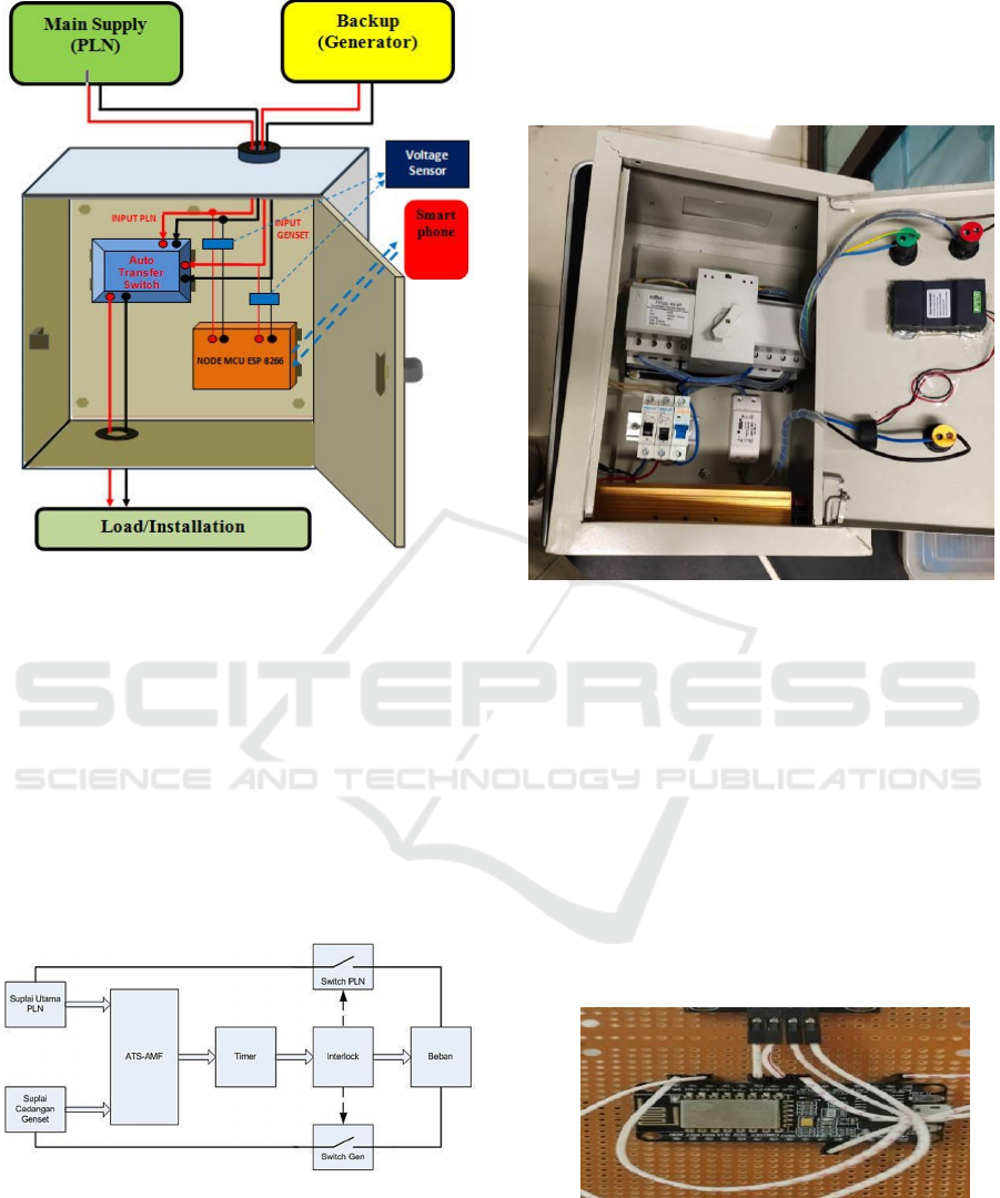
Figure 4: Hardware Design.
C
Auto Transfer Switch (ATS) Panel Design
In this study, the design and manufacture of an
Auto Transfer Switch (ATS) control system includes
hardware and software. Hardware is the stage of
work in the production process for making panels
and preparing the equipment and supplies needed for
ATS panels. In addition, a wiring design drawing is
also made on the ATS panel. While software is an
installation work and setting settings on Internet of
Things (IoT) software so that the control system can
operate according to predetermined settings.
Figure 5: Circuit of Auto Transfer Switch (ATS).
3 RESULT
A
Hard Ware Assembly
The manufacturing process starts from making a
series of Auto Transfer Switches for automatic
supply transfer control. Next is the control panel.
Figure 6 shows the Auto Transfer Switch panel
created by this research.
Figure 6: Auto Transfer Switch Panel.
B
NodeMCU ESP8266 Testing
NodeMCU is an electronic board based on the
ESP8266 chip with the ability to run microcontroller
functions and also an internet connection (WIFI).
NodeMCU is usually analogous to an Arduino board
that is connected to the ESP8266 into a board that
has been integrated with various features like a
microcontroller so that in programming only a USB
data cable is used.
Because the main source of NodeMCU is
ESP8266 especially ESP-12 series which includes
ESP-12E. So the features owned by NodeMCU will
be more or less similar to the ESP-12.
Figure 7: Testing NodeMCU esp8266.
In testing NodeMCU, that is by entering the
program
that has been made and then uploading it.
Indicates
the program has succeeded or failed in the
upload
process. As in Figure 8 and Figure 9.
iCAST-ES 2021 - International Conference on Applied Science and Technology on Engineering Science
966
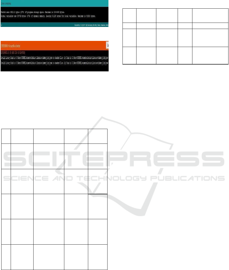
Figure 8: Program Uploaded Successfully.
Figure 9: Programs Failed to Upload.
C
ZMPT101B Voltage Sensor Testing
Voltage sensor testing is carried out to see sensor
error percentage. This test was carried out 10 times.
Table 1 is a test of the ZMPT101B Voltage Sensor.
Table 1: A test of the ZMPT101B Voltage Sensor.
D
Interlock Test
This test is used to determine the system
Interlock
according to the state of the sensor
readings to
find out suitable for know whether the
automatic
switching of the power supply is
appropriate with
the program.
Table 2: Interlock when main supply is off.
No
Main
Supply
Backup
Supply
Time
(S)
Description
1 On Off - Main Supply
2
Off
On
0,3
Indicator
lights up
and
sends
notification
3
On
Off
0,3
Indicator
lights up
and
sends
notification
From table 2 it can be explained that when the
main supply is not available then the switch will
switch, disconnect the main switch and connect the
backup supply switch with a time delay of 0.3
seconds and the system will send a notification to
the android.
4 CONCLUSION
After testing in this research, it can be concluded as
follows: The designed monitoring system has been
tested for 1 hour in data transmission. From all test
data can be sent and with the average delivery delay
time is 0.49 minutes. It is usage IoT for monitoring
system is stated to work well. The average
monitoring system test results for the input voltage
of 222 Volts, output voltage of 223 Volts. ATS
based
IoT is relatively affordable than factory-made
ATS
panels or PLC-based modules. So it is suitable
for
use by the home industry.
REFERENCES
Autade Prerane, S. G .Galande, An Embedded 1/3
Phase
Automatic Transfer Switch Tranfer Switch
Controller
With Intelligent Energy Management,
IJCT,Volume 2,
Issue 2, 2013
Bill Brown, P. E., Jay guditis, Critical-Power
Automatic
Transfer Systems Design and
Application, 2006
Doso, 2013, ATS (Automatic Transfer Switch),
http://dosooce.blogspot.com/2013/10/ats-
A
utomatic-
transfer-switch.html diakses tanggal
03 Mei 2021
Enggar T. Santosa, Maradu S., Suripto, 2011,
Rancangan Dasar Sistem Automatic Main
Failure dan
Automatic Transfer Switch untuk
Ruang Pertemuan
Gedung 71, Proceeding
Pertemuan Ilmiah Rekayasa
Perangkat Nuklir
PRPN-BATAN
Hasaafu, Ambo, L.O.A.R., Hande, S., 2012,
Rancang
Bangun ATS-AMF Berbasis PLC,
Jurusan Teknik
Elektro Politeknik Negeri Ujung
Pandang Makassar.
No
Input
Voltage
(Volt)
Testing with a
multimeter
(Volt)
Average
Voltage
(Volt)
Error
(%)
1
190
187
188
189
190
191
189
0.5
2
200
198
199
201
202
203
200.6
0.3
3
210
212
213
214
215
216
214
1.9
4
220
221
223
224
225
226
223.8
1.7
5
230
233
234
235
236
237
235
2.1
Auto Transfer Switch (ATS) Panel Design based on Internet of Things (IoT)
967

Indrawan, A.W., Hamdani, Nuraminah, 2016,
Rancang
Bangun Sistem Kendali Dan
Monitoring ATS/AMF
Dalam Pengalihan
Sumber Energi Listrik
Menggunakan
Mikrokontroler, ELEKTRIKA, hh.
130 – 141. ISSN 1412-8764
Jagra Bagus Haryanto, Perancangan Automatic
Main
Failure Dan Automatic Transfer Switch
DilengkapiDengan 10 Kondisi Display dan 4
Kondisi
Back Lighting Menggunakan Zelio
Logic Smart Relay
(SR), Universitas Diponegoro,
2012
Mochamad Fajar Wicaksono, 2017, Implementasi
Modul
Wifi NodeMCU ESP8266 Untuk Smart
Home, Jurnal
Teknik Komputer Unikom –
Komputika –Volume 6,
No.1 -2017
Muhammad Nur Shiha, 2011, Rancang Bangun
Sistem
Automatic Transfer Switch (ATS) dan
Automatic
Main Failure (AMF) PLN-Genset
berbasis PLC
Dilengkapi Dengan Monitoring,
Jurusan Teknik
Elektro Industri PENS-ITS,
Surabaya 60111
Riki Rizaldi, 2018, Perancangan ATS (Automatic
Transfer Switch) Satu Phasa Menggunakan
Kontrol
Berbasis Relay dan Time Delay Relay
(TDR), Journal
of Electrical Power Control and
Automation, Vol. 1
No. 2 HAL. 59-64
iCAST-ES 2021 - International Conference on Applied Science and Technology on Engineering Science
968
