
The Implementation of D155A-2 Bulldozer Sterring Overhaul
Al Amin, Halman and Andreal Imran
Heavy Vehichle Study Program, Nunukan State Polytechnic, Jl. Ujang Dewa, Nunukan, Indonesia
Keywords
:
Overhaul, Steering System, Components, Bulldozer D155A - 2.
Abstract
:
Bulldozer is a unit that uses a track shoe or commonly called a crawler engine, where the steering system used
in this unit uses a clutch with the basic principle of a disc consisting of an inner drum and an outer drum.
When the unit is moving straight the clutch must be tightened so that the rotation can be transferred to the
final drive and when the unit is going to be rotated the clutch must be released (stretched) so that the torque
and power of the transmission are balanced. Overhaul bulldozer D155A-2 is a maintenance activity that aims
to restore the state of a unit to its original state or according to factory standards. Steering overhaul activities
include removing components from the unit, initial cleaning, component disassembly, washing, inspection,
measurement, assembly, testing. adjustment, and installation on the unit. Some components such as dist,
coupling and inner drum that are not standard must be replaced. The mechanism for steering overhaul
activities as well as checking and measuring each component of the steering brake so that it can deepen and
find out the causes of the damage contained therein and take precautions and actions if there is damage to the
steering wheel. system.
1
INTRODUCTION
Heavy equipment is a tool that can be used to assist
humans in doing work not only in the mining sector,
the construction of an infrastructure, but also in
plantation fields. For these matters there are some
steps need to be done (Hadi, 1992). The selection
of heavy
equipment that is not appropriate to the
conditions and
situation of the work field. It is
avoiding the rate of
losses results such as low
production, below
performance of target production,
and improper repair
losses (Rochmanhadi, 1992). the
type and number of equipment and their
descriptions
need to be identified both their function
and
applications (Septiani et al., 2019).
In term of a vehicle unit such as heavy equipment,
it cannot be separated from the steering system. This
steering system functions is to control the direction
under the driver or operator control. That why
maintenaning and repairing of the steering system
must be well maintained in order to no errors occurs
during the operation of vehicle unit. Heavy
equipment, especially bulldozers, the steering system
is usually called a steering and braking system where
the systems are interrelated (Qing, 2015). Based on
the research
conducted by Carlo Ackermann et al.
that the
combines internal steering and braking is
avoiding collisions (Ackermann et al., 2015). The
research conducted by Zhank et al.
also shows that
the combination of steering and
braking is avoiding
unexpected riders (Zhang and Wu, 2016), while
based
on the research conducted by Vivas et al.
shows that
the suspension, steering and braking is
the main
controls in advanced level control (Vivas-
Lopez et al., 2015)
When the unit is running in the straight line, the
clutch must be in the engagement position on both the
RH (right) and LH (left) clutches, so the rotation of
the transmission is transferred to the final drive to
move the sprockets. In this matter, the clutch must be
disengaged to be able to turn the unit. It is also the
rotation and power of the transmission is not passed
to any of the final drives in order to the sprockets can
be controlled. Likewise, when experiencing is
damage, an overhaul of the steering and braking
system must be carried out, then disassembly and
checking of both parts must be carried out. It needs to
be done because the components of both parts are
located in the same place. Based on these
considerations, It is necessary to do the research
regarding to an overhaul steering study on a large tool,
namely the Bulldozer D155A-2.
896
Amin, A., Halman, . and Imran, A.
The Implementation of D155A-2 Bulldozer Sterring Overhaul.
DOI: 10.5220/0010956300003260
In Proceedings of the 4th International Conference on Applied Science and Technology on Engineering Science (iCAST-ES 2021), pages 896-900
ISBN: 978-989-758-615-6; ISSN: 2975-8246
Copyright
c
2023 by SCITEPRESS – Science and Technology Publications, Lda. Under CC license (CC BY-NC-ND 4.0)
2
RESEARCH METHODS
2.1 Collecting Data
Data were collected by observation, library
research, and interviews. Observations directly in the
field during the process of overhaul activities are
carried out, observations are made when needed. Data
collection by library research in this study refers to the
shop manual D155A-2 and the Standard Operational
Procedure (SOP). Meanwhile, the interview process is
carried out by interviewing directly to the mechanic
or supervisor.
The data collected is divided into 2 parts including
primary data and secondary data. Primary data
collection will be done by making some notes of
observation and documentation in the fields.
Secondary data collection was obtained from
published company data, including: (1) Machine
Condition Report (MCR); (2) Recommended Part List
(RPL); (3) Quality Assurent (QA) D155A-2; (4) Job
Sheet Schedule (JSS); and (5) Standard Operational
Procedure Overhaul and shop manual bulldozer
D155A-2.
2.2 Data Processing
The data obtained were then will be grouped based
on
the order of the overhaul processing. Then the
results obtained are compared with the shop manual
and SOP overhaul in order to obtain accurate results
and it could avoiding the deviation and errors.
3
RESULTS AND DISCUSSION
This research is divided into 3 parts such as: (1)
implementation of overhaul steering brake system; (2)
results of overhaul steering brake system; and (3)
discussion on overhaul steering brake
3.1
Implementation of
Overhaul
Steering Brake System
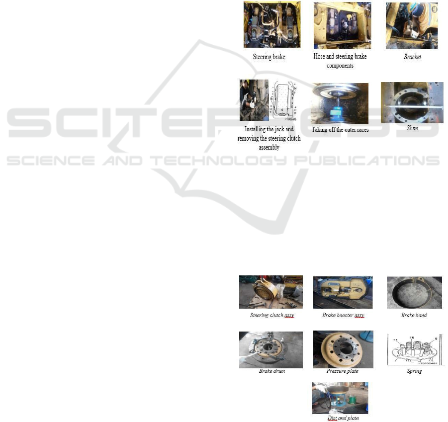
Carry out steering overhaul are by removing the
steering brake and then disassembly of the steering
brake. The first step is to remove the steering brake
and then to open the plug that is under the unit at the
bottom of the steering brake. The next step is to
remove the linkage from the steering and brake
pedals. It is also necessary to remove the spring assist
brake cylinder and then to remove the hoses that are
still attached. The next step is to mark the critical
points by marking the location on each component
with the RH and LH mark. Marking aim is to make
the installation process easier. The next then remove
the chord rod that is inside the steering brake cover so
that the cover is detached from the bracket, and
remove the brake booster assy. Use a rope or sling that
is physically small but strong to lift the bracket and
steering clutch assy, lift it with the help of a crane
(same RH/LH parts), then remove the steering clutch
assy and remove the bavel gear shaft assembly. Next,
pay attention to the shim on the edge of the signpost
or the right and left sides. After the removal work is
complete, close the steering case so that dirt and other
objects don't get in, and then wash all the components
of the steering brake so that the disassembly process
is easy (Figure 1).
Figure 1: Remove steering brake.
The disassembly process is carried out carefully,
which will be disassembly of the brake booster assy,
cleaning and then washing components. After that
disassembly steering clutch assy, then the critical
point is "this process must be done carefully because
the spring has a large enough strength, about 200kg
large spring, 150kg small spring". The process is
carried out carefully (Figure 2).
Figure 2: Disassembly steering brake.
The Implementation of D155A-2 Bulldozer Sterring Overhaul
897
3.2 Result of Overhaul Steering Brake
System
This process is divided into several, namely the
first
is a visual check and measurement. This section is
checked and measured carefully, referring to the QA
sheet or guided using the shop manual according to the
unit so that the results obtained are more accurate and
do not deviate from the standard. There is also a visual
check that usually looks for dents, cracks, dirt or
anything else contained in these components.
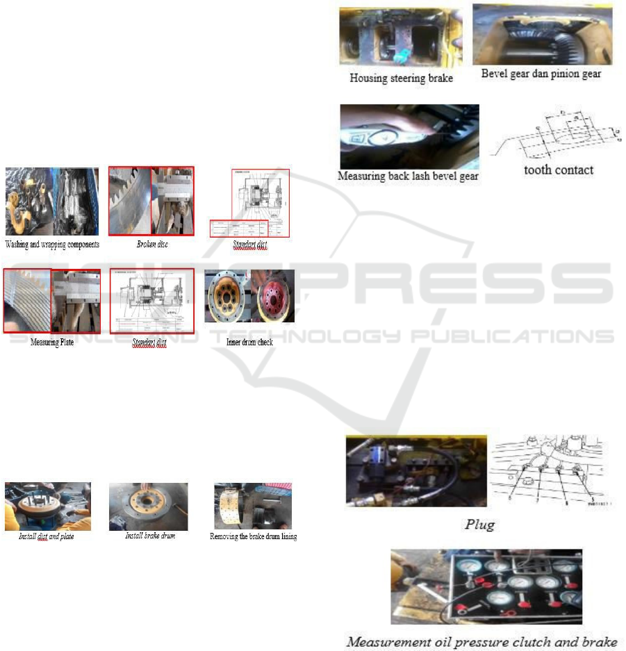
This first part is done by washing and cleaning all
components and classifying which ones use diesel,
using soapy water and only using a cloth, and wrap it
using plastic krap to wait in assembly or check and
measure first. After that visual check and measurement
on the dist and plate, then check on the visual check
and measurement on the plate, then check on the inner
drum (Figure 3).
Figure 3: Disassembly steering brake.
The second is the component assembly process.
This assembly part is done in the right way and
carefully. After performing a visual check on the
brake drum lining and seeing its age, the brake drum
lining must be replaced (Figure 4).
Figure 4: Assembly component.
The third part to do is install the bavel gear. This
process is carried out by installing the outer races
(signs) and measuring the thickness of the shims,
installing the bolt mouting outer races but not
tightening them first (RH, LH). Then set the bavel gear
in the case, then install the shaft from the right clutch
housing, insert the shaft in the center hole of the bavel
gear to the left housing, install the appropriate shim, so
that the bevel gear center. Then tighten the bolt
mounting outer races and install or tighten the bolt
mounting bavel gear by using special tools and the
same method when removing, after that clean the
steering brake housing until it is completely clean
(because the housing is where the oil is) so that the oil
is not contaminated, and also Clean the transmission
bavel gear and pinion gear for measurement. Perform
measurement acklash´on the bavel gear (Figure 5).
Figure 5: Install bever gear.
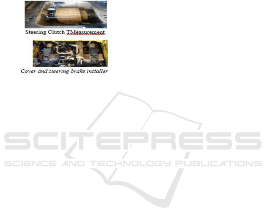
The fourth process is to install the steering brake. This
process is done by cleaning the steering brake
housing, then attaching the steering clutch assembly
to the housing. After that, the steering clutch (RH,
LH) was measured. Then install the right and left side
mounting bolts and tighten them, and also install the
bracket, brake booster assy, attach the pins, connect
the small host that is on the brake band. After that,
adjust the steering brake on the spring assist brake,
then install the steering brake cover and torque bolt,
then fill in the steering oil for testing and adjusting
(Figure 6).
Figure 6: Install steering brake.
The fifth process is testing and adjusting the steering
brake. The process carried out is running the engine
iCAST-ES 2021 - International Conference on Applied Science and Technology on Engineering Science
898
and measuring the oil pressure (Figure 7). Then the
last process is replacing the filter and strainer.
Previously the filter had not been replaced due to
flashing the impurities contained in the new
components, after which the filter and strainer were
replaced after a test run (Figure 7).
Figure 7: Testing and adjusting steering brake.
3.3 Discussion
on Overhaul
Steering
Brake
Based on the results of the inspection and
measurement of the overhaul activities above, several
damaged components must be repaired or replaced.
The possibilities that cause damage to these
components must also be known, so that preventive
measures can be taken so that they can extend their
service life and minimize expenses for component
repair or replacement. These components include: (1)
the dist and plate have scratches and dents which are
most likely caused by the steering oil being
contaminated by grams from the friction of objects
that come into contact in the steering case. Even
though at the time of measurement it was still within
the standard limits, but because of these defects, the
dist and palte components had to be replaced because
it could result in not optimal steering performance; (2)
The inner drum has a fairly severe crack which is most
likely due to the unit undergoing heavy work or it
could be due to the age of use that has passed the
standard limit and must be replaced; (3) The brake
drum lining on visual inspection of the brake drum
lining already looks thin and it can also be seen from
the historical unit that the canvas has never been
replaced, so that during this overhaul, the lining must
be replaced; (4) Tooth on the bavel gear at the time of
measurement is still in good condition because the
contact points made at the time of checking are still
within the standard limits, as well as measurements on
the backlash are still within the standard limits, so that
the bavel gear can still be used; (5) the oil pressure
measurement shows that the steering and brake
pressure has been achieved, so that during operation
the unit will not experience trouble when turning and
will not be held back when the clutch and brake work.
Because when the pressure on the clutch and brake is
not reached, it can cause a malfunction in the steering
system.
4
CONCLUSIONS
The results showed that the overhaul process must
be
in accordance with the Standard Operating
Procedure (SOP) so that the mechanism can be
controlled and run properly, always referring to the
shop manual as a guide for accuracy in every overhaul
steering process. The steering overhaul work includes
remove, namely removing the steering and brake
components from the unit, prewashing, disassembly,
namely dismantling steering and brake components,
washing, inspection and measurement, namely visual
inspection and measurement of the dist-plate-inner
drum-bevel gear-campus components. brake-oil
pressure-hose, assembly, testing and adjusting, and
installing the steering brake components on the unit.
After checking and measuring the steering and brake
components, the results obtained include: (1) the
thickness of the dist 4.65mm (standard 4.7mm repair
limit 3.7mm) it can be said that the thickness of the
dist is still within the standard, but there are scratches
so it must be replaced ; (2) the thickness of the plate
is 2.85mm (standard 2.9mm repair limit 2.0mm) it can
be said that the thickness of the plate is still within the
standard, but there are molds that must be replaced;
(3) the RH inner drum is badly cracked and must be
replaced; (4) measurements on the bevel gear, tooth
contact are still within the standard limits and the
backlash is calculated at 6kgm (standard 2-6kgm) so
that the backlash is declared safe; (5) brake lining is
not up to standard so it must be replaced; (6) on the
oil pressure when checking, the results are 15kg/cm²
for the clutch and 16.5kg/cm² for the brake so that the
oil pressure is reached.
When checking finds components that are not
standard, they must be replaced, because if they are
not replaced, they will result in multifunction, namely
malfunctions or not working optimally on the system
and errors during operation of the unit. Things that
must be done in the future when going to do overhaul
steering and brakes, namely when doing work must
always refer to the SOP, mark components, document
activities, and check consistently before installing.
The Implementation of D155A-2 Bulldozer Sterring Overhaul
899

ACKNOWLEDGEMENTS
There are many obstacles in completing this
research, and this work would not have been possible
without the support of several parties.
For that, I would like to thank all parties who have
been willing to work so far and other related writings.
Director of the Nunukan State Polytechnic who has
provided support to me in completing this research.
I also want to thank my family and friends who
have always supported me in completing this
research.
REFERENCES
Ackermann, C., Bechtloff, J., & Isermann, R. (2015).
Collision avoidance with combined braking and
steering. In 6th International Munich Chassis
Symposium 2015 (pp. 199-213). Springer Vieweg,
Wiesbaden.
Hadi, R. (1992). Alat Berat dan Penggunaannya.
Rochmanhadi, T. (1992). Alat-Alat Berat dan
Penggunaannya: Departemen Pekerjaan Umum.
Septiani, M., Afni, N., & Andharsaputri, R. L. (2019).
Perancangan Sistem Informasi Penyewaan Alat Berat.
JUSIM (Jurnal Sistem Informasi Musirawas), 4 (02),
127–135.
Qing, L. I. (2015). Study on the Simulation of Steering
and Brake Valve of BullDozer# br# Based on
SimulationX. CHINESE HYDRAULICS &
PNEUMATICS, (11), 114.
Vivas-Lopez, C. A., Tudon-Martinez, J. C., Hernandez-
Alcantara, D., & Morales-Menendez, R. (2015).
Global chassis control system using suspension,
steering, and braking subsystems. Mathematical
Problems in Engineering, 2015.
Zhang, L., & Wu, G. (2016). Combination of front
steering and differential braking control for the path
tracking of autonomous vehicle (No. 2016-01-1627).
SAE Technical Paper.
iCAST-ES 2021 - International Conference on Applied Science and Technology on Engineering Science
900
