
Design of Permanent Magnetic Yoke for Subsurface Defect Detection
with Magnetic Particle Inspection Methode
Mohammad Anas Fikri, Auliana Diah Wilujeng
and Muhammad Faizal Eka Prasetya Putra
Politeknik Negeri Madura, Jl. Raya Camplong Km. 4, Taddan, Sampang, Indonesia
Keywords
:
Magnet, NDT, Permanent Magnetic Yoke, Subsurface Defect.
Abstract
:
The development of magnetic particle inspection testing is not only focused on testing materials placed
indoors, where the need for electrical resources is the main thing. The increasing number of requests to carry
out Non-Destructive Test (NDT) testing with the magnetic particle inspection method makes inspectors
unable to speculate whether in open areas such as mining areas there is a power source available. To reduce
the speculation of inspectors about the limited electrical resources in the open area, a permanent magnetic
yoke was designed. Permanent magnetic yoke is an NDT testing tool with a magnetic particle inspection
method that does not use an electric power source but uses permanent magnets. Yoke material used is Al6061
with a thickness of 50mm. The magnet used is a Neodymium type permanent magnet. The working principle
of a permanent magnetic yoke uses the properties of permanent magnetism with the magnetic particle
inspection method in areas where there is no power source Based on the results of the comparison test between
Permanent Magnetic Yoke and DC Yoke through the same treatment, the level of accuracy of reading
subsurface defects on welding joints of steel material with dimensions of 300 x 150 x 10 mm with 3G position
SMAW welding process using permanent magnetic yoke is 96.78%.
1 INTRODUCTION
The development of manufacturing is currently
increasingly advanced, especially in welding
technology or engineering because it has an important
role in metal engineering and repairing. The
manufacturing process for metal in modern times
currently involves many elements of welding,
especially in the fields of design. In the welding
process, not all the results of the metal connection are
good. There must be a defect and discontinuity in the
metal resulting from the connection. Some of these
defects include defects that are on the surface (surface
defect) and defects below the surface (subsurface
defect). When welding doesn’t pay attention to the
guidelines contained in the Welding Procedure
Specification (WPS) and Procedure Qualification
Record (PQR) documents, generally the product will
experience defects in welding.
Defects in the welding process will affect the
material strength of a product. This is very vulnerable
and it is the responsibility of a WI (Welding
Inspector) to maintain in order to minimize and even
eliminate defects, namely starting from
theemergence of porosity clusters which result in
repairs
in the welding process (Warman, 2017).
In the process of welding work equipment from
excavators, such as parts of the excavator boom,
which use thick steel plate material, it is necessary to
use special welding techniques. This technique is
used to avoid defects that often occur in the boom
joint welding process of excavators. Defects can be
detected and identified using non-destructive testing
with one of the methods, namely magnetic particle
inspection (Pardede and Hendroprasetyo, 2015).
Several research have begun to use magnets as a
defect identification with NDT (Non Destructive
Test) using the Magnetic Particle Inspection method.
In the research that has been done, it can be concluded
that the effectiveness of reading using Magnetic
Particle Inspection will decrease along with the
increase in the thickness of the nonconductive coating
from the actual crack size. while in particle magnetic
examination, magnetization can use an electromagnet
yoke (AC current) and permanent magnet. Permanent
magnet yoke has different sensitivity with AC yoke
in detecting surface defects. AC yoke is good at
detecting surface cracks while permanent magnet
806
Fikri, M., Wilujeng, A. and Putra, M.
Design of Permanent Magnetic Yoke for Subsurface Defect Detection with Magnetic Particle Inspection Methode.
DOI: 10.5220/0010954000003260
In Proceedings of the 4th International Conference on Applied Science and Technology on Engineering Science (iCAST-ES 2021), pages 806-813
ISBN: 978-989-758-615-6; ISSN: 2975-8246
Copyright
c
2023 by SCITEPRESS – Science and Technology Publications, Lda. Under CC license (CC BY-NC-ND 4.0)
yoke is better at detecting cracks on the subsurface
(Dyatmika and Akbar Putra, 2012)
1.1 Magnet
µ
r
= µ
material /
µ
o
(1)
with:
µ
r
: Relative permeability of a material
Any
text or material outside the aforementioned
µ
material
:
Material Permeability
margins will not be
printed.
Magnets are metals that can attract iron or
steel and have a magnetic field. The word of
"magnet" is thought to have come from the word
"magnesia" which is the name of an area in minor of
Asia, where magnets were first thought to have been
discovered by humans. In the Magnesia area, rocks
that can attract iron and steel were first found, which
in turn were called magnets (Puspita and Rohima,
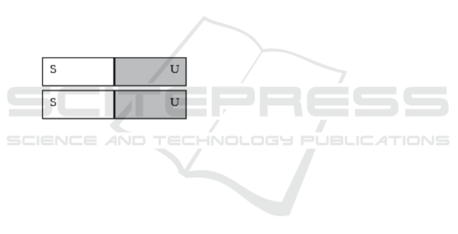
2009). Magnets always have two poles, a north pole
and a south pole. The basic concept of magnetic poles
is shown in Figure 1.
Figure 1: Magnetic Poles (Puspita and Rohima, 2009).
The magnetic poles are the ends of the magnet that
have the greatest power to attract iron particles
compared to other parts of the magnet. Every magnet
has two poles, namely a south pole and a north pole.
The straight line connecting these two poles is called
the magnetic axis. If we hang a magnet and hold it
still, the longitudinal direction of the magnet always
points in a north-south direction. For a while, if a
magnet is cut, each piece will still have two poles and
become a new magnet (Puspita and Rohima, 2009).
Magnetic permeability is the degree of
magnetization of a material in responding linearly to
a magnetic field. According to international units, the
permeability of the vacuum has a value of 4π×10-7
TmA-1 or 12.57×10⁻⁷ TmA-1 (Serway and Jewett,
2004). The value of the permeability of a magnetic
material is not constant, which largely depends on the
magnitude of the magnetizing force applied to it. The
permeability of a magnetic material is always
compared to the permeability of a vacuum, where this
comparison is called relative permeability (Lusyana,
Toifur, and Rohman, 2014). Relative permeability is
defined by equation 2.3 as follows (Lusyana, Toifur,
and Rohman, 2014). The relative permeability of a
material can be calculated by the equation 1.
µ
o
:
Vacuum Permeability.
1.2 Magnetic Properties
According to their properties, magnets can be
divided into:
1.
Temporary Magnet
Temporary magnets are magnets whose
elementary magnetic arrangement easily returns
to
irregularity after the magnetic material is used
as a
magnet (Puspita and Rohima, 2009).
2.
Permanent Magnet
Permanent magnets are magnets whose
elementary magnetic arrangement is difficult to be
disorganized again so that they have a relatively
long durability to become a magnet (Widodo
et al,
2009). At this time there are many kinds of
permanent magnets that are often used based on
the
material, including Barium ferrite, and
Neodymium
Iron Boron (NdFeB) Magnets
(Irasari and Idayanti,
2009).
a.
Barium Ferrite Magnet (BaFe
12
O
19
)
Barium ferrite magnets began to be
developed in
the early 1960s, as an alternative
to the use of metal
magnets. This magnet
belongs to the classification
of hard magnetic
ceramic materials that have a
hexagonal
structure (BaFe12O19) (Irasari and
Idayanti,
2009).
The advantage is that the price is cheaper
when
compared to other permanent magnets,
causing
barium ferrite magnets to be very
preferred to be
applied as permanent magnets
(Irasari and Idayanti,
2009).
b.
Neodymium Iron Boron (NdFeB)
In 1980, Neodymium Iron Boron (NdFeB)
magnets
were discovered with high strength,
and they have
been commercialized since
November 1984.
NdFeB is a rare earth type
permanent magnetic
material, because it is
formed by 2 atoms of a
rare earth element
neodymium (Nd), 14 atoms of
iron (Fe) and 1
atom of boron (B), so the molecular
formula
formed is Nd2Fe14B (Irasari and
Idayanti,
2009).
The magnetic characteristics of NdFeB are
better
than other permanent magnets. Because it has better
and higher magnetic
characteristics than other
magnets, in its
application NdFeB magnets have
small
dimensions and volume. The application of
NdFeB magnets is quite a lot, such as in
electronic
equipment, electric motors,
generators, sensors,
Design of Permanent Magnetic Yoke for Subsurface Defect Detection with Magnetic Particle Inspection Methode
807
automotive industry,
petrochemical industry and
medical
equipment products (Irasari and Idayanti,
2009).
The drawback is that it cannot be applied
at
high temperatures, which is only a
maximum range
of up to 200
0
C. In addition,
these magnets are
quite expensive and have
low corrosion resistance,
so that in their
application a surface treatment is
required,
such as being coated with nickel, zinc or
gold
(Irasari and Idayanti, 2009).
Non-destructive testing or non-destructive testing
is defined as an inspection, test or evaluation applied
to a material to determine the structure or components
in the material in order to maintain the quality of the
material use process (Ministry of Transportation,
2016). In NDT testing, it can determine the condition
of the material and can detect any defects or damage
to the material.
In the periodic inspection of non-destructive
testing, the Magnetic Particle Inspection method has
standard tests that must be carried out so that a
construction is declared safe. The standard contains
Acceptance Criteria so that a construction is declared
safe to use, it must go through a testing process based
on applicable standards. The recognized standards of
Magnetic Particle Inspection testing and evaluation
are:
▪
Legislation No. 1 of 1970 concerning Work
Safety.
▪
Legislation No. 13 of 2003
concerning
Manpower.
▪
ASME (American Society of
Mechanical
Engineering) Sec.V Article 7
▪
ASTM (American Standart for Testing Material)
E3024,709 8
2
MATERIALS AND METHODS
2.1
Materials
Making this research requires several tools and
materials as a support in the process of making these
tools. The tools and materials used are as follows:
2.1.1
CNC Milling/Milling Machine
In the research, the CNC Milling machine used
type
Brother S500XI for making magnetic grip
frames on
Permanent Magnetic Yoke.
2.1.2
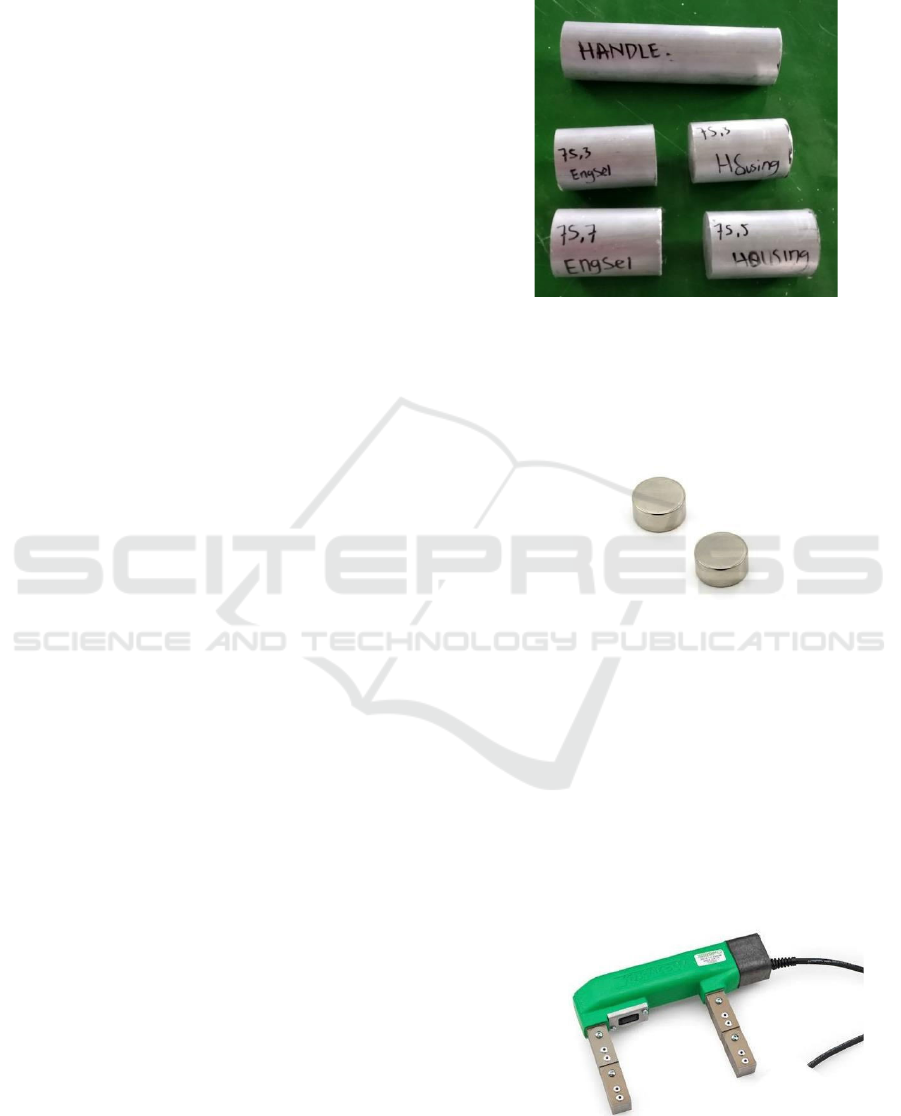
Aluminium Al6061
In the research, the material used for the
manufacture of the design / frame of the handle
is
mild steel type Al6061
Figure 2: Materials Al6061.
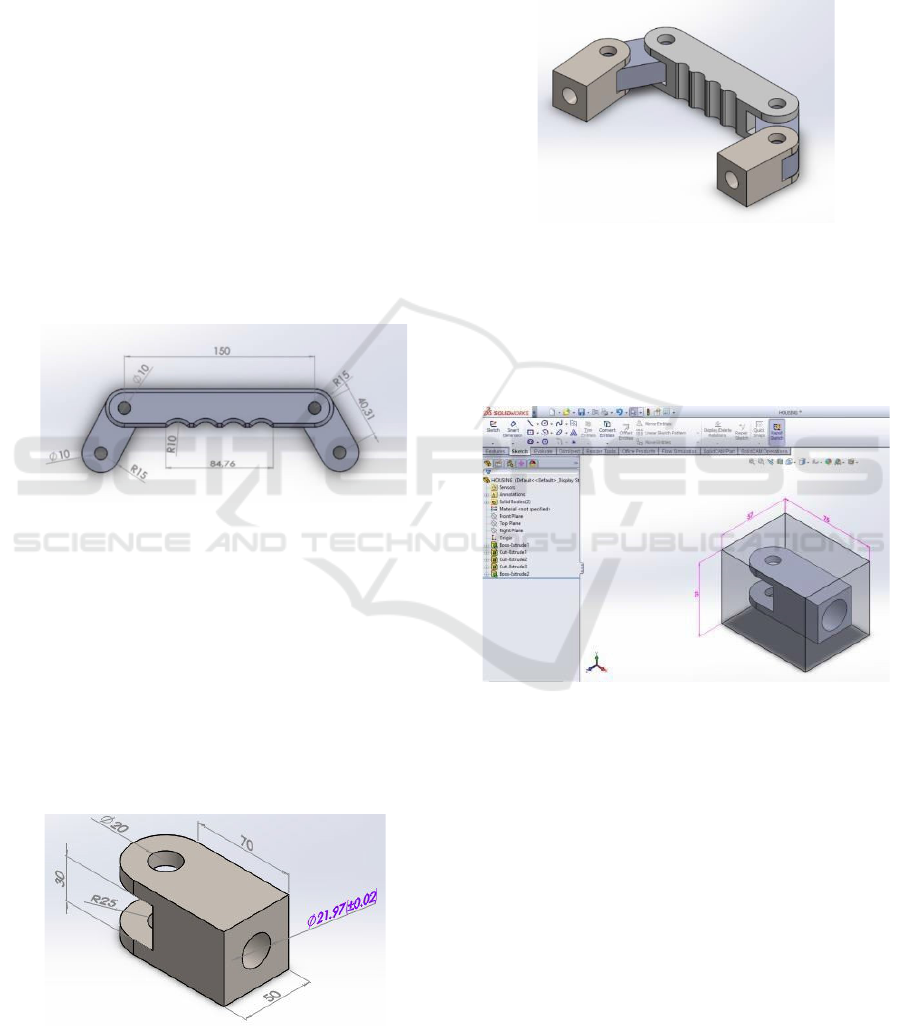
2.1.3
Neodymium Magnets
Neodymium magnets are used for the
magnetization
process of the workpiece to be
inspected so that
it can find out the existing
defects.
Figure 3: Neodymium Magnet.
2.1.4
Calibration Metal (18.2 Kg)
Calibration metal weighing 18.2 kg (40 lb) was
used
for the calibration of the Permanent
Magnetic
Yoke before being applied for the
inspection
stage to the workpiece.
2.1.5
Magnetic Yoke AC/DC
The AC/DC magnetic yoke in Figure 3 is used
as a
comparison of the test results of the
permanent
magnet yoke.
Figure 4: Magnetic Yoke AC/DC.
iCAST-ES 2021 - International Conference on Applied Science and Technology on Engineering Science
808
2.2
Methods
In the manufacturing process, the workpiece
design process goes through the CAD (Computer
Aided Design) process. CAD (Computer Aided
Design) is a computer program for designing a
product. The CAD process is very necessary as an
initial design before making a product using the
manufacturing process. Basically, CAD can be in the
form of 2-dimensional or 3-dimensional technical
drawings with detailed drawing descriptions to make
it easier for the next processing. In the process of
making this research design using Solidworks.
This permanent magnetic yoke design is based on
3 main parts, Handle Yoke, Link Yoke, and Housing
Magnet Yoke, where all manufacturing processes are
carried out with 3 axis CNC Milling. The geometric
shape of each part of the permanent magnetic yoke is
as follows. Figure 5 has shown handle yoke and link
yoke design.
Figure 5: Handle Yoke and Link Yoke.
Yoke handle serves as the holder of the permanent
magnetic yoke test equipment. The design of the
handle yoke design follows the morphology of the
inspector's fingers so that it does not cause work
accidents on the fingers during the testing process.
The link Yoke functions to adjust the length and
shortness of the test area so that the effectiveness of
the performance of the magnet during testing
becomes better. Magnet housing has shown on Figure
6.
Figure 6: Housing Magnet.
The housing magnet serves as a place for the
Neodymium permanent magnet to be implanted. The
size of the housing magnet hole is made using a fitting
adjustment tolerance, so that the magnet insertion is
carried out with the help of heating on the housing.
Permanent Magnetic Yoke design has shown on
Figure 7.
Figure 7: Permanent Magnetic Yoke Design.
Furthermore, the CAD softcopy of the three-part
design will be imported into the CAM software for
CAM programming to be made before being
executed on the CNC Milling machine. CAM
programming has shown on Figure 8.
Figure 8: CAM Programming.
Making the CAM program still refers to the
appropriate parameters for machining raw materials.
The examples of G-Code simulation programs above
and their explanations has shown on Table 1.
Before being executed on a CNC machine, it is
necessary to verify in the form of a toolpath
simulation from the CAM program that has been
created. One form of the simulation has shown on
Figure 9.
Design of Permanent Magnetic Yoke for Subsurface Defect Detection with Magnetic Particle Inspection Methode
809
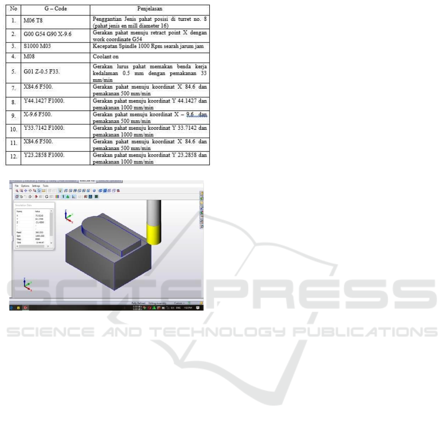
Table 1: G-Code program for Housing.
Figure 9: Toolpath CAM simulation.
3
RESULTS
Testing of the permanent magnetic yoke is carried
out by referring to the ASME Sec standard code. VIII
Mandatory Appendix 6 of 2009 with criteria for
acceptance of defects in the Magnetic Particle
Examination testing method. An indication of a
defect is evidence of the imperfection of a material
caused by certain things. Only indications having
dimensions (dimensions) greater than 1/16 inch
(1.5mm) will be considered. Evaluation of indications
according to ASME Sec.VIII Mandatory Appendix 6:
a.
A linear indication is one having a length greater
than three times the width
b.
A rounded indication is one of circular or elliptical
shape with a length equal to or less than three
times its width.
c.
Any questionable or doubtful indications shall be
reexamined to determine whether or not they are
relevant.
These acceptance standards shall apply unless
other more restrictive standards are specified for
specific materials or applications within this Division.
All surfaces to be examined shall be free of:
a.
relevant linear indications;
b.
relevant rounded indications greater than 3 ∕ 16 in.
(4.8 mm);
c.
four or more relevant rounded indications in a line
separated by 1 ∕ 16 in. (1.6 mm) or less, edge to
edge.
Based on SEC ASME standards. 5 article 7
regarding Magnetic Particle Inspection, the AC Yoke
testing procedure is different from the Permanent
magnet yoke. However, for the evaluation and
analysis of defects that occur in the material, it still
refers to the ASME Sec. VIII Mandatory appendix 6.
3.1
Equipment and Material Used
Equipment Used:
a.
duster
b.
AC Yoke
c.
Lighting
d.
Iron Brush
e.
Light Meter (Lux Meter)
f.
Ruler
Material Used:
a.
Cleaner
b.
White Contrast (WCP-2)
c.
Wet Pacticle (7HF)
3.2
Procedure Test
a.
Prepare tools and electrical resources, then test the
strength of the AC yoke first (Power Lifting of
Yoke) based on ASME section V Article 6 (T-
773, 2), namely for AC current the yoke must be
able to lift a load of 4.5 kg (10 lbs). If the yoke can
still lift the required load, then the yoke is still
suitable for use. This lifting power test is usually
carried out once a year.
b.
Clean the surface of the test specimen from oil,
and other impurities in the form of rust, grease,
paint, and other impurities with a cleaner
c.
Spray the test specimen with White Contrast Paint
(WCP 2) evenly.
d.
Wait for the white contrast paint to dry (dwell
time).
e.
Arrange the yoke in such a way that it can
magnetize the test specimen properly and during
the process of magnetizing the test specimen the
yoke is placed in different positions so that all
discontinuities in the test material are visible, both
cracks on the surface and subsurface.
f.
When the yoke is magnetized, the test specimen is
sprayed with wet particle so that the defects in the
test material appear.
iCAST-ES 2021 - International Conference on Applied Science and Technology on Engineering Science
810
g.
Observing discontinuities and defects.
h.
Demagnetization or removal of magnetic residue
on the specimen after evaluation.
i.
Post Cleaning
4 DISCUSSION
The level of accuracy in the process of reading
and measuring defects is very necessary in
determining whether the workpiece is suitable for use
or not. Basically, precise measurement and
calibration of precision measuring instruments can
support the success rate in data analysis.
To determine the performance of the permanent
magnetic yoke test equipment, a welding defect
detection test was carried out on the test specimen in
the form of steel with a 3G connection type SMAW
welding process. The test also uses a DC yoke as a
comparison. The following are the results of welding
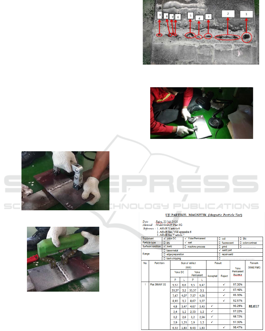
specimen testing, has shown on Figure 10 and Figure
11.
Figure 10: Permanent Magnetic Yoke testing.
Figure 11: Comparison with Yoke AC/DC.
Identification of defects in the weld metal of the
test specimen can be seen in the following Figure 12.
Figure 12: Specimen Test Results with Permanent
Magnetic Yoke.
Figure 13: Test Specimen Defect Measurement.
Measurement of defect readings on test specimens
can be seen in the following Figure 13:
Table 2 is the test result data and analysis of the
accuracy of Permanent Magnetic Yoke and DC Yoke
readings.
Table 2: Comparison of Yoke DC and Permanent
Magnetic Yoke readings
Based on the results of the permanent magnetic
yoke test with a DC yoke comparison, the following
results were obtained, has shown on Figure 14.
Design of Permanent Magnetic Yoke for Subsurface Defect Detection with Magnetic Particle Inspection Methode
811
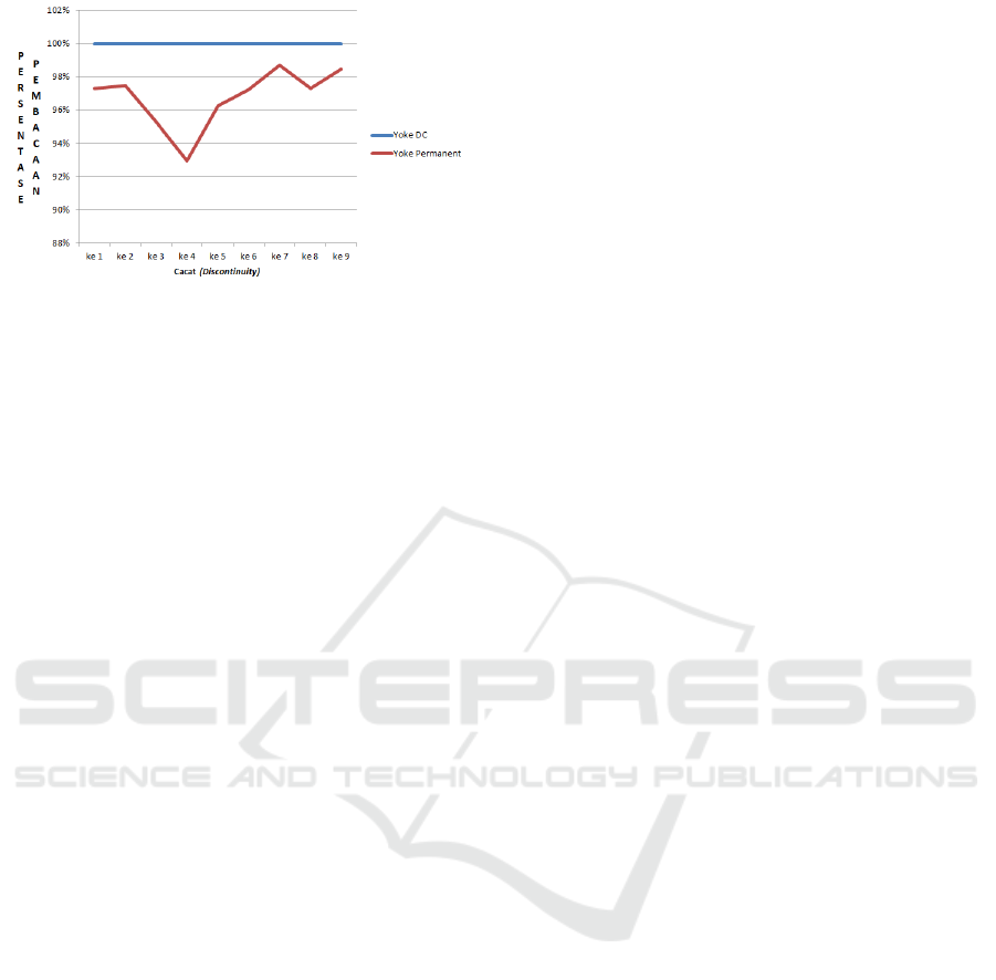
Figure 14: Defect Reading Comparison.
Based on the data in Figure 13, the Yoke DC
reading is always 100% because the reference for
comparison in this study is the "Magnaflux" brand
DC Yoke which has been tested and calibrated with
reference to the ASME BPVC, ASTM E1444, ASTM
E709 standards.
For Permanent Magnetic Yoke readings, the
average reading accuracy is 96.78% because at the
time of making the permanent Yoke it was not
calibrated to the standard applicable to the NDT test
classification.
In the 4th defect indication, it was found that there
was a significant decrease in the percentage due to
several factors, one of which was an error in
measurement due to the concave position of the
defect and the irregular shape of the defect, so the
measurement could not be precise with the original
size of the defect (Nurachmandani, 2009).
5 CONCLUSION
After analyzing and collecting data using the
Permanent Magnetic Yoke, it can be concluded as
follows:
a.
The percentage of accuracy in reading Permanent
Magnetic Yoke defects is 96.78%. These results
are obtained by reference to readings from Yoke
DC Magnaflux which have been calibrated to
international standards.
b.
The increasing trend in the graph of the Permanent
Magnetic Yoke test results shows that the
effectiveness of the test equipment with the base
material of Neodymium permanent magnets is
reliable enough to be used in open areas such as
mining and shipyards.
The suggestions that can be given for further
development and research are as follows:
a.
The results of several tests and data analysis,
should be for accuracy in reading defects using a
special specimen (test object) in the form of a
measurable artificial defect.
b.
Substitution in the selection of Permanent
Magnetic Yoke material does not only pay
attention to the light weight and ergonomics
aspects, but the material characteristics also need
to be considered. The basic nature of aluminum
material turns out to be able to weaken the
magnetic properties.
REFERENCES
ASME INTERNATIONAL. (n.d.). ASME (American
Society of Mechanical Engineering) Sec. V Article 7.
Dyatmika, I. G., & Akbar Putra, W. H. (2012). Analisis
Perbandingan Metode MPI Menggunakan Yoke AC
dan Permanen Magnet Untuk Pendeteksian Panjang
Retak Permukaan yang Dilapisi Cat Pada
Sambungan
Las di Kapal. JURNAL TEKNIK POMITS, 1(1), 1-4.
Irasari, P., & Idayanti, N. (2009, Oktober). APLIKASI
MAGNET PERMANEN
BaFe
12
O
19
DAN NdFeB
PADA
GENERATOR MAGNET
PERMANEN
KECEPATAN RENDAH SKALA
KECIL. Jurnal Sains Materi Indonesia, 11, 38 - 41.
Kementerian perhubungan. (2016). Administration and
control of aircraft welding and non destructive test.
Peraturan direktur jenderal perhubungan udara no.
Kpp 122 tahun 2016.
Lusyana, A., Toifur, M., & Rohman, F. (2014, Nopember).
UJI SIFAT MAGNETIK PASIR PANTAI MELALUI
PENENTUAN PERMEABILITAS RELATIF
MENGGUNAKAN LOGGER PRO. Jurnal Fisika, 4
No.2.
Ministry of Transportation. (2016). 5 Year Plan for
Transportation Infrastructure Development.
Nurachmandani, S. (2009). Fisika 1 Untuk SMA/MA
Kelas X. Jakarta: Grahadi.
Pardede, L, & Hendroprasetyo, W. A. (2015). Analisa
Perbandingan Sensitivitas Metode Magnetic
Particle
Inspection (MPI) Menggunakan Metode
Visible Dry,
Visible Wet, dan Wet Fluorescent
Terhadap
Pendeteksian Panjang Retak pada
Permukaan dan
Toe Sambungan Las di Kapal yang Dilapisi
Nonconductive Coat. JURNAL SAINS DAN
SENI
ITS, 4(1), 2337-3520.
Puspita, D., & Rohima, I. (2009). Alam Sekitar, IPA
Terpadu Untuk SMP/MTs Kelas VIII. Jakarta: Leuser
Cita Pustaka.
Serway, R. A., & Jewett, J. W. (2004). Physyc for Scientist
and Engineers (6th ed.). California: Thomsoon
Brooks/Cole.
Widodo, A., Kim, E. Y., Son, J. D., Yang, B. S., Tan, A.
C., Gu, D. S., ... & Mathew, J. (2009). Fault diagnosis
of low speed bearing based on relevance vector
machine and support vector machine. Expert systems
with applications, 36(3), 7252-7261.
iCAST-ES 2021 - International Conference on Applied Science and Technology on Engineering Science
812

Warman , S. P. (2017, Jul). ANALISIS FAKTOR
PENYEBAB CACAT PENGELASAN PADA PIPA
(Study Kasus Pada Pipa Distribusi PDAM Kabupaten
Kutai Barat). Jurnal Mekanikal, 8(2), 730-736.
Serway, R. A., & Jewett, J. W. (2004). Physyc for Scientist
and Engineers (6th ed.). California: Thomsoon
Brooks/Cole.
Design of Permanent Magnetic Yoke for Subsurface Defect Detection with Magnetic Particle Inspection Methode
813
