
Design of Parking Brake Lock: RFID based
Motorbikes Security Module
Muhammad Firdaus Jauhari
and Yuan Perdana
Automotive Mechanical Engineering, Politeknik Negeri Banjarmasin, Brigjen Hasan Basri, Banjarmasin, Indonesia
Keywords: Motorbike, Security, Microcontroller, Brake, RFID.
Abstract: The project is related to the design of a module that serves to increase the security of motorbikes, which will
be used to prevent vehicle theft. The developed module works based on the Parking Brake Lock and RFID
system. Wheel locking is enabled when the motorbike is parked using a smartphone synchronization with a
microcontroller as a control unit, and an RFID reader will identify the ID tag for the function of starting and
turning off the motorcycle engine. The designed security module shows good results as expected.
1 INTRODUCTION
In general, many security systems have been
developed for vehicles, especially cars and
motorbike, which aim to prevent the theft of these
vehicles. Another use of a security system on a
vehicle is that we can add a function to track the
position of the vehicle if a thief manages to break into
the existing security system. In developing countries,
vehicle theft crimes are counted quite a lot every year
(Pranata et al., 2020). The average number of
motorbike theft cases is always more than car theft,
this is because the motorbike security system is
simpler and easier for thieves to penetrate, compared
to the car security system. Besides, the business of
selling stolen motorbike is also quite large, easier,
profitable, and organized.
A new type of security developed for today's
modern vehicles is the smart keyless entry and start
system (Francillon, Aurélien; Danev, Boris; Capkun,
2014). This system is a technology to replace
conventional keys or physical keys which are
generally used to start the vehicle. The drawback
from the user's point of view is that if the remote key
is damaged or lost, the replacement of the remote key
must be by the immobilizer ID registration
programmed by the manufacturer. We can use our
additional safety for our vehicles as an alternative
solution. As in research that developed an anti-theft
vehicle security system for preventive action,
vehicles are equipped with GPS and GSM technology
to protect, monitor and track the vehicle (K. A.
Mamun, 2016). In another study, a security system for
motorbike was designed using three security systems
in the form of an RFID scanner, RF communication
module, and a GPS function. The RFID scanner
functions as an additional key, if other than the
registered card (tag) it cannot turn on the relay. The
RF communication module functions to turn off the
motorbike engine automatically if there is a distance
of n meters between the driver and the motorbike. The
GPS functions to monitor and track the location of
motorbike (Isyanto et al., 2018). Another variation of
the antitheft vehicle security system was presented by
(Naina Kaushik, Mayur Veralkar, Pratik Parab,
2014), the security system works by matching the
fingerprints of registered car drivers. The matching
process uses Matlab and the results will be displayed
on the LCD. If a car is stolen, the car's fuel tank will
be locked so that when the tank is empty, it cannot
refill fuel.
In this paper, the author proposes an additional
vehicle security system that utilizes parking brake
locks and RFID sensors. The parking brake lock is the
first layer of security and the RFID sensor is the
second layer of security that is connected to the
vehicle's electrical system for the prevention of
motorbike theft.
Jauhari, M. and Perdana, Y.
Design of Parking Brake Lock: RFID based Motorbikes Security Module.
DOI: 10.5220/0010953100003260
In Proceedings of the 4th International Conference on Applied Science and Technology on Engineering Science (iCAST-ES 2021), pages 761-765
ISBN: 978-989-758-615-6; ISSN: 2975-8246
Copyright
c
2023 by SCITEPRESS – Science and Technology Publications, Lda. Under CC license (CC BY-NC-ND 4.0)
761
2 METHOD
2.1 System Overview
For the design of this study, we used an experimental
method which was used to determine the effect of the
independent variable on the outcome variable under
controlled conditions. At the initial stage, the
equipment and components needed are determined in
advance, and as the control unit, the Arduino
microcontroller is chosen to run the program created.
Arduino Uno is a microcontroller board that is fully
controlled by the ATmega328. The Arduino Uno has
14 digital input or output pins, 6 analog inputs, a 16
MHz crystal oscillator, a USB connection, a power
jack, an ICSP header, and a reset button (Kadir,
2017). The other main components used in this design
are RFID MFRC522, df player, speaker, Bluetooth
HC-06, smartphone, DC motor, compact step down,
APK boarduino, and relay module.
The steps in designing the motorbikes security
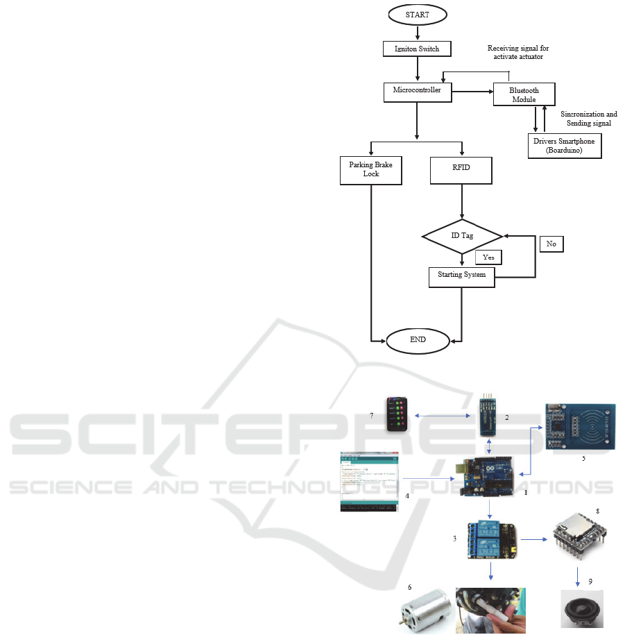
module that we propose follow the control flow as
shown in Figure 1. The way of module works is when
the motorbike is stopped and parked, the driver will
use the parking brake lock and after the ignition
switch is OFF the motorbikes security module will
automatically disconnect the starting system.
Meanwhile, to be able to run a motorbike, the driver
must follow the vehicle security procedures that have
been set according to the design in this study. After
the ignition switch is ON, the first step is to
synchronize the module with the smartphone via a
Bluetooth connection, so that the microcontroller can
disable the parking brake lock. Next, the
microcontroller needs to get a signal from the
registered ID tag scan and activate the motorbike
starting system. Figure 2 shows the system
architecture consisting of hardware and software used
as components of this motorbikes security module.
The software used for programming syntax is
Arduino IDE as an intermediary device between the
microcontroller and the Arduino compiler (Banzi &
Shiloh, 2014).
2.2 Block Diagram Description
The block diagram in Figure 3 below explains how
the proposed motorbikes security module works.
After the ignition switch is in the ON position, the
electric current from the power source for the security
module that uses a 12 v battery from a motorbike will
be passed through a compact step down so that it
drops to 8 v, according to the safe working voltage
range for the Arduino microcontroller. The incoming
Figure 1: Control flow of the proposed system.
Figure 2: Embedded system architecture.
8v voltage will activate the Arduino microcontroller,
and turn on the Bluetooth module to synchronize the
signal with the android smartphone. If the
synchronization is successful, the driver can drive the
actuator by sending commands to the Arduino
microcontroller via a smartphone. The first function
that is activated is the release of the parking brake
lock so that the wheels are not locked, then the RFID
sensor identifies the ID Tag that has been registered
in the database. To turn on the engine, it takes one
time to scan the ID Tag which is recognized by the
iCAST-ES 2021 - International Conference on Applied Science and Technology on Engineering Science
762
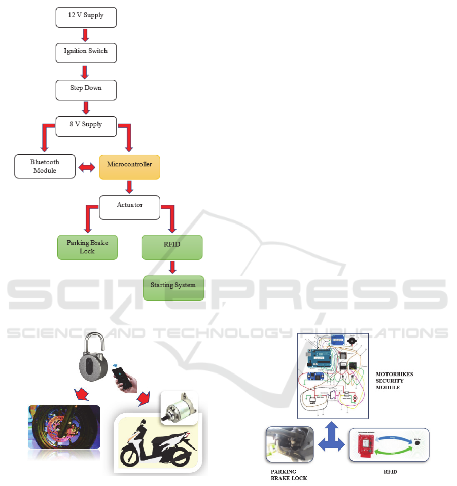
system so that the motorbike can run and to turn off
the engine, do a second ID tag scanning process.
Figure 3: Block diagram of proposed system.
Figure 4: Locking of wheel and starting system.
In the engine OFF condition, and the motorbike will
be parked, the driver can lock the front wheel of the
motorbike by activating the parking brake lock
feature and the module will automatically disconnect
the starting system as shown in Figure 4. In this
condition, even though the ignition key has been
forcibly tampered with, the motorbike still cannot run
because the front wheel has been locked and the
starting system on the motorbike is not active.
3 RESULT AND DISCUSSION
After the motorbikes security module design process
is complete, the module is packaged in a
dimensionally appropriate box. The module is placed
at the bottom of the motorbike seat so that it is not
visible and avoids water. The next step is to make
minor modifications to the brake handle to install a
DC motor component that has been given a sleeve so
that it can function as a parking brake lock. You do
this by adding a bolt of the appropriate length at the
end of the DC motor, this bolt will hold the movement
of the brake handle later. Followed by connecting the
starting system circuit with the motorbikes security
module so that it can function as additional security
on the vehicle. How it works, the starting system
circuit line will be cut off automatically when the
ignition is in the off position, in this case, the starter
switch is replaced by a relay module for the starter
relay input to turn on the motorbike (Figure 5). The
process of assembling and testing motorbikes security
modules can be seen in Figure 6 below. At the top is
the process of inputting the ID Tag pin and testing its
identification, then installing the module that has
been packaged in a box on the motorbike trunk. While
the bottom of the picture shows the installation
process on the motorbike starting system circuit, and
finally the motorbike turn on and turn off process
using the ID Tag.
Figure 5: Vehicle security module wiring.
For the safety factor of the module, the voltage that
supplies the Arduino microcontroller power is
maintained in the 7-9 Volt range. This is to avoid
overheating conditions on the Arduino components
and several other components that can cause damage.
The voltage measurement is carried out using a
multimeter in the section before the step down and
after the step down, and the measurement results can
be seen in Table 1 below.
Design of Parking Brake Lock: RFID based Motorbikes Security Module
763

Figure 6: Module assembly and testing processes.
Table 1: Voltage Measurement.
Measurement Variables Voltage
(
Volt
)
Vin (before step
down)
Voltage 12
Vout (after step
down
)
Voltage 8.0
The results of the tests that have been carried out
show that the module can work according to the initial
design. Because the module has functioned as an
additional security system on the motorbike, the
module will start working when the motorbike is
parked to avoid the crime of vehicle theft. If the
motorbike stops, the driver can lock the motorbike
wheel to park by synchronizing the smartphone with
the security module using a Bluetooth connection,
and after turning the ignition switch to the off
position, the wiring starting system is disconnected.
In addition to measuring the voltage, an ID tag
recognition test was also carried out which had been
inputted into the database module. Based on testing,
the module can identify all ID tags well, can
distinguish between ID tags that have been inputted
and not inputted in the database module. For the ID
tag identification position that is given a barrier, the
module can still read properly up to a distance of 10
cm. When the motorbike will be used, the first step,
as usual, is the ignition switch in the ON position, so
that the current from the battery which has been
lowered to 8 v provides power to activate the Arduino
microcontroller. The driver then unlocks the wheel by
activating the actuator on the parking brake lock,
through a command given to the microcontroller. For
the motorbike starting process, the driver needs to
scan the ID tag once on the RFID reader so that the
module will start the motor starter. When the engine
is running, the speaker will sound “Motor ON”
indicating the motorbike starting process is
successful. After that, if the motorbike will be turned
off, the driver needs to scan the second ID tag on the
RFID, and the speaker will sound "Motor OFF".
4 CONCLUSIONS
There are many ways to increase the security of
motorbikes from the possibility of theft, one of which
is using the motorbikes security module that uses a
parking brake lock and RFID device to increase the
level of security. This module is used to prevent the
crime of motorbikes theft through the release of the
parking brake lock via a smartphone and ignition of
the motorbike via registered ID Tags. This research
can complement the types and methods of using
microcontrollers and RFID which are implemented as
motorized vehicle security devices.
ACKNOWLEDGEMENTS
We would like to thank P3M of Politeknik Negeri
Banjarmasin for the incentive support for the
publication of this paper, as well as colleagues and
students of the Department of Automotive
Mechanical Engineering who have assisted in the
suggestions and work of this project.
REFERENCES
Banzi, M., & Shiloh, M. (2014). Make: Getting started with
Arduino. In Computing in Science and Engineering.
Francillon, Aurélien; Danev, Boris; Capkun, S. (2014).
Relay Attacks on Passive Keyless Entry and Start
Systems in Modern Cars. Research Collection, 1–16.
https://doi.org/10.3929/ethz-a-010025751
Isyanto, H., Solikhin, A., & Ibrahim, W. (2018).
Perancangan dan Implementasi Security System pada
Sepeda Motor Menggunakan RFID Sensor Berbasis
Raspberry Pi. RESISTOR (ElektRonika KEndali
TelekomunikaSI Tenaga LiSTrik KOmputeR), 2(1), 29–
38. https://doi.org/e-ISSN : 2621-9700, p-ISSN : 2654-
2684
K. A. Mamun, Z. A. (2016). Anti-theft vehicle security
system with preventive action. IEEE.
https://doi.org/10.1109/APWCCSE.2015.7476241
Kadir, A. (2017). Pemrograman Arduino dan Processing
(1st ed.). Elex Media Komputindo.
Naina Kaushik, Mayur Veralkar, Pratik Parab, K. N.
(2014). Anti-Theft Vehicle Security System.
International Journal for Scientific Research &
Development|, 1(12), 2845–2848. https://doi.org/ISSN
(online): 2321-0613
iCAST-ES 2021 - International Conference on Applied Science and Technology on Engineering Science
764

Pranata, M., Anggraini, D., Makbuloh, D., & Rinaldi, A.
(2020). Prediksi Pencurian Sepeda Motor
Menggunakan Model Time Series (Studi Kasus: Polres
Kotabumi Lampung Utara). BAREKENG: Jurnal Ilmu
Matematika Dan Terapan, 14(3), 425–434.
https://doi.org/10.30598/barekengvol14iss3pp425-434
Design of Parking Brake Lock: RFID based Motorbikes Security Module
765
