
Design and Development of SHIPS-ROV
Budianto
1a
, M. Basuki R.
2
, Imam Sutrisno
2
, Zindhu Maulana
2
, Eko Julianto
3
and Arie Indartono
3
1
Shipbuilding Engineering, Politeknik Perkapalan Negeri Surabaya, Surabaya, Indonesia
2
Electrical Engineering, Politeknik Perkapalan Negeri Surabaya, Surabaya, Indonesia
3
Marine Engineering, Politeknik Perkapalan Negeri Surabaya, Surabaya, Indonesia
Keywords: Remotely Operated Vehicle, Underwater, Bio- fouling, Performance, Corrosion, Design, Development.
Abstract: Ships that are operating can experience damage to the hull during operation, including: damage to
deformation, fatigue, corrosion etc. The presence of bio-fouling attached to the hull makes the hull plates thin
due to the formation of deposits or deposits on the hull caused by marine life. This will cause the condition
of the ship’s structural strength to decrease due to the decreasing moment of inertia of the structure due to
thinning plates. Therefore, it is necessary to inspect the condition of the ship’s hull after a period of operation.
The amount of the bio-fouling component will affect the speed of the ship as well because the condition of
increasing ship resistance increases if the bio-fouling is not cleaned from the hull. This paper describes a
development of SHIPS-ROV (Ships building Institute of Polytechnic Surabaya-ROV) as a device that help to
monitor the condition off ship’s hull.
1 INTRODUCTION
Some of the damage to the hull in operations include
deformation, cracks, fatigue, fouling, corrosion, thus
requiring an earlier hull investigation process so that
more hull damage does not occur. The number of
marine transportation accidents, such as ship
collisions can result in some parts of the ship being
deformed or the condition of the hull breaking which
causes a hull leak that causes the ship to sink. The
condition of bio-fouling in the hull, a condition where
the thickness of the hull plate is reduced due to the
presence of marine life attached to the hull, these
conditions can be in the form of deposit formation,
encrustation, curding, deposition, scaling, scale
formation, slagging, and mud formation. Therefore,
the Bureau of Classification will always check the
thickness of the hull plate every year in terms of
issuing the feasibility of the ship in sea operations, but
the docking process must be carried out and this
requires no small cost. Therefore, SHIPS-ROV
technology is urgently needed to directly investigate
the condition of the hull submerged in water, both due
to fouling and even deformation or crack conditions
in the hull. ship hull for low- cost investigation
processes with simpler size and function capacity
a
https://orcid.org/0000-0002-4155-5008
settings but using reliable technology and materials.
In the process of designing SHIPS-ROV, a design
method with the latest technology is needed so that
optimum product results are obtained with a few rows
of wasted material. The latest product design
technology can control material requirements,
structural strength, and product optimization forms
and can more easily carry out the inspection process
for the product design process. Some of the SHIPS-
ROV product design processes with product design
methods can be grouped into three parts, including:
• Computer Aided Design (CAD) is a computer
software program for the process of drawing a
product or part of a product component. Products that
are designed can be represented with lines or symbols
that have certain meanings according to applicable
standards. In CAD it can be a 2D or 3D drawing.
• Computer Aided Engineering (CAE) which is
the use of computer software in product design that
assists technical propulsion system, controlled and
piloted by an on board analysis tasks. Such as finite
element methods (FEA), fluid dynamics (CFD), and
optimization.
• Computer Aided Manufacturing (CAM) which
is a design process in the form of working drawings
and G-code results that can be directly used in the
756
Budianto, ., Basuki R., M., Sutrisno, I., Maulana, Z., Julianto, E. and Indartono, A.
Design and Development of SHIPS-ROV.
DOI: 10.5220/0010953000003260
In Proceedings of the 4th International Conference on Applied Science and Technology on Engineer ing Science (iCAST-ES 2021), pages 756-760
ISBN: 978-989-758-615-6; ISSN: 2975-8246
Copyright
c
2023 by SCITEPRESS – Science and Technology Publications, Lda. Under CC license (CC BY-NC-ND 4.0)
production process. In CAM includes the needs of
row material, G-code, working drawings, assembly
drawings and others.
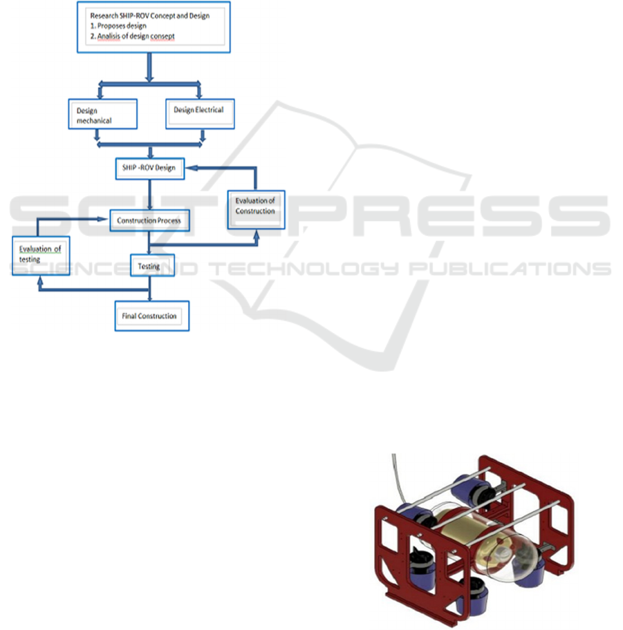
2 SHIPS-ROV DESIGN
Figure 1 shows the step by step process of the
design and development of SHIPS-ROV. The first
step is to identify the system requirements.
Specifications will be owned by SHIP-ROV. This
step will determine the design and equipment
Figure 1: Overall Flow of design of HIP ROV.
requirements of the SHIPS-ROV. The later step,
determine the mechanical design and electrical
design. To develop the mechanical design, Fusion
360 software is used to draw and animate the SHIPS-
ROV that are proposed and expected and AutoCAD
software is used to electrical design for internal and
external. The last step is to test and evaluate the
imperfections of the SHIPS-ROV system and the
weaknesses of the mechanical design and electrical
design of the SHIPS-ROV
3 GENERAL DESIGN OF AN
SHIPS-ROV
In the development of regulation in Ship-RUV
construction some applicable regulations are such as
BKI, ABS, GL, NK, BV and others. Each
classification of the regulation has a critical content
in performing standard in accordance with the results
of research and design.
There are several aspects that need to be considered
in mechanical design and electrical design in order to
success- fully obtain a suitable circuit for SHIP-ROV.
In ship design where in determining the main size and
line plan includes several designs, including:
determining the main size of the ship, determining the
design of comparison ships, making CSA and shape
control body plans. (Budianto, 2018). Some floating
object designs have a fairly high level of difficulty.
The amount of weight placed in light weight and
death weight should not be more than the planned ship
displacement. CAD technology Computer Aided
Design (CAD) is a computer software program for the
process of drawing a product or part of a product
component. Products that are designed can be
represented with lines or symbols that have certain
meanings according to applicable standards. In CAD
it can be a 2D or 3D drawing. Computer Aided
Engineering (CAE) which is the use of computer
software in product design that assists engineering
analysis tasks. Includes for finite element methods
(FEA), fluid dynamics (CFD), and optimization.
Computer. Aided Manufacturing (CAM) it is a
design process in the form of working drawings and
G-code results that can be directly used in the
production process. In CAM can covers the needs of
row material, G-code, working drawings, assembly
drawings and others. In designing a SHIP-ROV that
operates in water, it is very necessary to have
knowledge of ship design, marine use materials and
the laws of physics that support the concept of
underwater vehicles and their environment.
Therefore, the major design aspects that need to be
considered are body design, material selection,
electric power. Figure 2 shows the SHIP-ROV design
using Fusion 360 software.
Figure 2 : The Ships-Rov Design.
Design and Development of SHIPS-ROV
757
3.1 SHIPS-ROV Structure Design
The SHIPS-ROV is designed to operate at a maximum
depth of 200 m. Therefore, it is very important to
calculate the strength of the SHIPS-ROV structure.
The important thing to note is,
1)
Cover strength in operation
2)
Effective Body of Ship-ROV Structure for
effective thickness and design applied
3)
Reduce Resistance
4)
Reduce Power Consumption
5)
Low-Cost
SHIPS-ROV must have a hull (enclosure) that is used
to place components so that it is always dry and
watertight. Components placed in the hull/enclosure
are used for hull investigations. The SHIPS-ROV
hull/enclosure should allow easy access and
maintenance of components, and allow for
modularity in the event of future changes or additions
[1]. In addition to being light and strong, the hull must
also be corrosion resistant because it will experience
a harsh saltwater environment. The tubular spherical
hull offers the best structural integrity; however, its
shape precludes efficient use of the available space as
most components and systems are rectangular. The
cylindrical hull provides the best alternative,
consisting of: high structural integrity and a form
conducive to housing electronic components. The
enclosure or main body or hull is the main component
in the MSB component in the SHIPS-ROV, which is
very protected from water entering the enclosure.
Some of the equipment placed in the enclosure
include: thruster, color camera, monochrome camera,
light- ing, multi beam sonar, Oil Compensated dome.
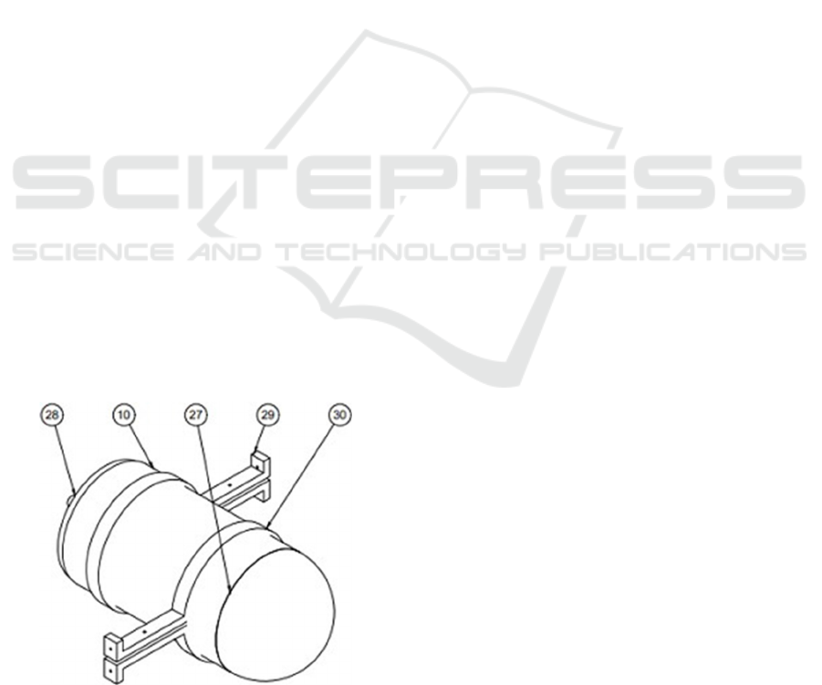
Dual imager and battery. Figure 3 shows the shape of
the SHIPS-ROV hull/enclosure.
Figure 3: Design of SHIPS-ROV Hull/enclosure.
Legend:
(10) Body shell
(27)
Body Head
(28)
Body AFT
(29)
Main support
(30)
Main support
3.2 Submerging
Because the SHIPS-ROV works underwater, for
diving the SHIPS-ROV must be able to increase the
downward force acting on it to counter the buoyant
force. This can be achieved using either an external
thruster i.e. a thruster and a propulsion motor for
forward, reverse, up and down of the SHIPS-ROV.
Details of the SHIPS-RUV enclosure components can
be given in the picture above which contains
component components including cameras, main
circuit boards, capacitors, and others. It is used in the
main function in the process of taking data and setting
the control of the motor and propeller which is
connected to the joystick of the control system. This
is a much simpler system, but quite inefficient in
terms of power consumption and not very suitable for
deeper depths. For the diving process, the SHIPS-
ROV is designed in such a way that it has residual
buoyancy. That is, the weight of the vehicle is made
approximately equal to the buoyant force.
3.3 Propulsion
Propulsion is required SHIP-ROV and is one of the
main sources of power consumption. SHIPS-ROV
uses a motor for propulsion. The location of the
motor will affect which degrees of freedom can be
controlled. Motor placement can affect noise
interference with onboard electronic components, as
well as propeller-to-hull and propeller-to-propeller
interac- tions. Propeller-to-hull and propeller-to-
propeller interactions can have unintended effects on
the dynamics of the SHIP- ROV maneuver. When
traveling at a constant speed, the thrust generated by
the motor is equal to the friction or resistance of the
vehicle, namely:
Thrust = Drag = 0.5s
2
A
CD
(1)
where is the water density, s is the speed, A is the
effective surface area and CD is the drag coefficient.
Power consumption for the propulsion system
increases dramatically as the vehicle speed
increases. This is because the thrust is equal to the
product of the thrust and the speed, meaning that the
thrust is a function of the cube of the speed,
iCAST-ES 2021 - International Conference on Applied Science and Technology on Engineering Science
758
Thrust
Power
=
Thrust x s
= 0
.
5
s
3
A
CD
...
(2)
Therefore, due to the limited energy supply of the
SHIPS- ROV. the one is functioned according to its
task, namely to investigate the hull of the ship. And
try not to travel at a speed that doesn’t draw too much
power, and in completing the task it doesn’t take too
long
3.4 Electric System
Electrical power is usually provided via a sealed
battery. The ideal battery arrangement is to connect
them in parallel with diodes between each battery to
allow for even discharge and to prevent current flow
between the batteries. Fuses or other protective
devices must also be used to prevent excessive current
flow in the event of a short circuit or component
malfunction. The limited power properties of the
SHIP-ROV affect the types of components and
equipment that can be used. Components and
equipment must be selected to draw as little power as
possible so that the battery can provide more than
enough time for the vehicle to complete its mission.
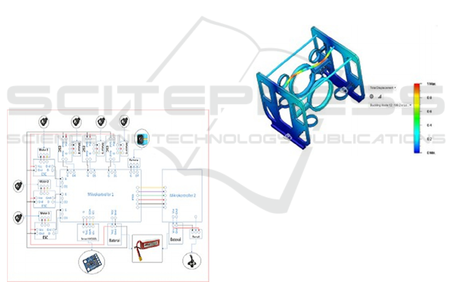
the arrangement of the electrical diagram is shown
in Figure 4
Figure 4: Design of SHIPS-ROV Hull/enclosure.
4 RESULT
SHIPS-ROV was designed in 3D using Fusion 360
software. This software allows users to easily design
and analyze the strength of the design. The steps in
the design process are as follows:
1.
CAD and Material Definition
At the beginning of the analysis can be done by
making CAD with existing components. Then do the
material definition using 5083 marine used aluminum
alloy material.
2.
Meshing
The meshing process is carried out to discuss the
object into the Ships-ROV constituent elements
which are conditioned in fine mesh conditions.
3.
Load and constraint
The loading process is placed in the loading area of
the structure which is then entered for the value of the
force acting. It’s as placement is applied at the bottom
of the structure.
Buckling Analysis of buckling load is an value -
passable condition in maintaining the strength of the
structure on the SHIPS-ROV. The buckling load is
very risky to the structure which can cause the
structure to break or deform. the results of the
buckling analysis are shown in Figure 5.
Figure 5: Buckling Analysis.
Mechanical and electrical structures have been
developed as described in the previous chapter.
SHIPS-ROV is an auxiliary equipment as a substitute
for divers to see the condition of the ship’s hull. Next
will be developed as a test bed platform for various
underwater researches, where the prototype
developed has a fixed mechanical system, has a
modular electronic system for the development of
various controllers, recording devices and sensor
modules.
Performance test was conducted to determine the
perfor- mance of SHIPS-ROV. Test l refers to the
specified technical specifications. Performance
testing can be carried out in sev- eral ways under
complete conditions, including: Progressive speed,
Circle rotation, Zigzag, Inertia Stop testing, Crash
Stop Ahead and Crash Stop Astern. Progressive speed
is a test to determine the speed of the test object,
because speed is very important in the characteristics
Design and Development of SHIPS-ROV
759

of the test object and this is one of the bargaining
abilities in its operation. Zigzag is a motion condition
of the test object in the form of maneuvering this
condition in real operation to determine the
characteristics of the test object in avoiding other
objects. Inertia stop test is a test to find out how far
the test object stops after the driving force is turned
off. It can also be used to find out how far the test
object is to avoid colliding with other objects. Crash
Stop forward and stern are test conditions to position
the test object to move forward and backward
simultaneously. Due to the limited size of the test
object, the performance test is carried out at least into
2 (two) main capabilities of the test object, namely:
Progressive Speed and Turning Circle Maneuvering.
ACKNOWLEDGEMENTS
Many thank s to lecture PPNS to support and sharing
knowladge.
REFERENCES
Budianto, M. T Wahyudi, U Dinata, Ruddianto & M.M.
Eko P. (2018). Strength Analysis on Ship Ladder Using
Finite Element Method. Journal of Physics: Conference
Series, 953, 012043, 1-8.
M. Abdul Hamid Koli, E. D, “Rancang Bangun Robot
Bawah Air Mini ROV (Remotely Operated Vehicles).”,
Jurnal Teknik Elektro Universitas Tanjungpura,(015,hal
1-10.
M Shahrieel M Aras, H A Kasdirin, M Herman Jamaluddin,
M Farriz Basar, “Design and Development of an
Autonomous Underwater Ve- hicle (AUV-FKEUTeM)
,” Proceedings of MUCEET2009 1 Malaysian
Technical Universities Conference on Engineering and
Technology June 20-22, 2009, MS Garden, Kuantan,
Pahang, Malaysia MUCEET2009
Surface ships: Principles of stability. [online], 2004.
Available:http://wrc.chinalake.navy.mil/warfighter
enc/SHIPS/shipeng/stability/basics/basics.htm/.
Imam Sutrisno, Mohammad Abu Jami’in and Jinglu Hu.
(2014). Modified fuzzy adaptive controller applied to
nonlinear systems modeled under quasi-ARX neural
network., Artificial Life Robotics, 19, 1, 22-26.
Marine structures. (1991). U.S. Patent No. 5,018,471.
Mhatt, Gouri, Emmanuel LefranÃ, and Gilbert Touzot.
(2012). Finite element method. John Wiley & Sons.
M. Abdul Hamid Koli, E. D. (2015). Rancang Bangun
Robot Bawah Air Mini ROV (Remotely Operated
Vehicles). Jurnal Teknik Elektro Universitas
Tanjungpura, 1-10.
Machine, W. (2009). Autonomous Vehicles, (2nd Ed).
Institute of Marine Technology, Bangladesh.
Tutu, S. (2017). Penyebab kerusakan kapal. (Edisi 1).
Surabaya.
Wahyudi. (2018). Dua Kapal Tabrakan di Perairan Kendari,
KM Bunga Melati 79 Tenggelam. Kendari: Basarnas.
iCAST-ES 2021 - International Conference on Applied Science and Technology on Engineering Science
760
