
An Improved Hysteresis Band based FCS MPC for Grid-connected
Three Phase Inverter
Hendi Purnata
a
, Galih Mustiko Aji
b
, Afrizal Abdi Musafiq
c
and Purwiyanto
Department of Electronics Engineering, State Polytechnic of Cilacap, Indonesia
Keywords: Optimization, FCS MPC, Inverter, Hysteresis Band.
Abstract: The Indonesian government has begun to promote the use of non-oil and gas alternative energy. Optimizing
renewable energy technology is a priority for system implementation. One method to overcome modulation
in one computational stage is by using a Finite control set – predictive control model (FCS MPC) compared
to traditional controllers such as PID, SPWM. This method is very challenging to find the optimal, especially
in the field of prediction that considers far into the future. FCS MPC in this method provides the latest
discovery by adding a hysteresis band to produce a better current. The results of research on optimization of
renewable energy technology apply with direct current response system of 882.7 Volts with a steady-state
error of 2 %. The optimal current has been obtained from the hysteresis band of 0.2 bands. On switching on
the inverter, the second vector voltage or g2 is 0.47or this vector value is used for switching on the inverter.
FCS MPC has been implemented to a two-level converter system, then the need for a filter circuit to produce
a sine wave like a pure sine wave generated by a generator.
1 INTRODUCTION
Indonesia has large renewable energy capabilities
such as hydropower, geothermal, wind, solar,
oceanic, or biomass. Sources of power generation
such as nuclear and fossil fuels depend on the
depletion of natural resources and the process of
generating electricity can damage the environment.
The right choice to be sustainable is to use renewable
energy because it has decent economic potential and
is environmentally friendly (Secretariat General Of
The National Energy Board Koutl Oo, n.d.).
The Indonesian government is starting to flock to
apply non-fossil renewable energy. The solution is
expected to be able to maintain the stock of energy
resources in Indonesia. Based on the National Energy
Policy (KEN), in 2025 Indonesia can use energy
sources with a composition of 77% fossil and the
remaining 23% from new and renewable energy. The
government reaffirmed in Law No. 25 of 2000 on
PROPERNAS (National Development Program) that
this policy is the main program to increase the use of
renewable energy. To achieve the National
a
https://orcid.org/0000-0003-2047-816X
b
https://orcid.org/0000-0002-1582-9597
c
https://orcid.org/0000-0002-8241-1000
Development Planning, the experts must be from
within the country, so that human resources can know
and implement the National Development Plan (iesr,
2019). Converter technology on renewable energy is
a special topic in this research, which focuses on the
energy results obtained from power electronics
devices, namely converters. Some of the problems
raised following previous studies look at the
problems, methods to the results obtained in previous
studies. The study (Lyu, Ma, Yan, 2020) explained
that MPC was introduced as a controller that can look
ahead or predict and take advantage of low
frequencies in switching and can manipulate system
stability. MPC can also overcome flux and torque
ripples. FCS-MPC is used to control power electronic
devices. The basic concept of this method is to predict
the system when switching then evaluate the cost
function which will be the optimal value and applied
to the next control. In the study (Vazquez et al, 2014)
applying FCS-MPC which is easier than conventional
controllers because this system is online to determine
the optimization value. Some of the advantages of
control in this study are the response generated is
748
Purnata, H., Mustiko Aji, G., Abdi Musafiq, A. and Purwiyanto, .
An Improved Hysteresis Band based FCS MPC for Grid-connected Three Phase Inverter.
DOI: 10.5220/0010952900003260
In Proceedings of the 4th International Conference on Applied Science and Technology on Engineering Science (iCAST-ES 2021), pages 748-755
ISBN: 978-989-758-615-6; ISSN: 2975-8246
Copyright
c
2023 by SCITEPRESS – Science and Technology Publications, Lda. Under CC license (CC BY-NC-ND 4.0)
dynamic, does not have a modular, fast response and
can overcome non-linear systems.
In addition, the problem in the output converter is
in the switching which results in harmonics. In this
study (Gendrin, Gauthier, Lin-Sh, 2016, p-5487),
overcoming network-connected switching using a
direct power control (DPC) sequence with a constant
frequency. Research (Zhang et al, 2017), the constant
switching frequency can be overcome but by using
large calculations and complex methods. Research
(Tarisciotti et al, 2014) made an FCS-MPC scheme to
overcome switching to get a constant frequency.
To get a good FCS-MPC computation, the
computation requires implementation time beyond
the switching of the phase-locked loop (PLL) and
maximum power tracking. To overcome this
limitation there is a modulated MPC (M2MPC) by
utilizing a constant switching frequency (Tarisciotti
et al, 2014) (Zhang et al, 2016) (Yang et al, 2017).
M2MPC is designed to control three-phase active
rectifiers by using seven levels of H-Bridge cascade
and using a matrix converter, therefore the
computational burden of using this method is very
large.
In the study (Guo et al, 2017) FCS-MPC using
commutation so that the current network can be
balanced. Efficiency in the form of a reduction in the
form of sectors on the inverter, other than in the
network can be used for speed control on a permanent
motor synchronous machine (PMSM) based on
torque and flux control. In this control, the order in
the inverter switching table is not considered (Nadour
et al. 2020).
Research by (Ali, 2021) (Purnata, 2017) combines
the hysteresis band and svpwm methods for current
and voltage improvement. Current improvement
utilizes the hysteresis band method while SVPWM
uses the voltage improvement method.
From some of the studies above, researchers have
an idea to apply FCS MPC to a converter connected
to the grid. This system is added a hysteresis band to
produce a current limit that is more optimal than the
ratio of the current value of idq.
2 MODELLING OF THE FCS
MPC WITH GRID
2.1 FCS MPC
Model Predictive Control (MPC) or predictive
control system is included in the design concept of
process model-based controllers, where the process
model is used explicitly to design controllers by
minimizing a criterion function. The underlying idea
for each type of MPC is (Wang et al, 2012). The FCS
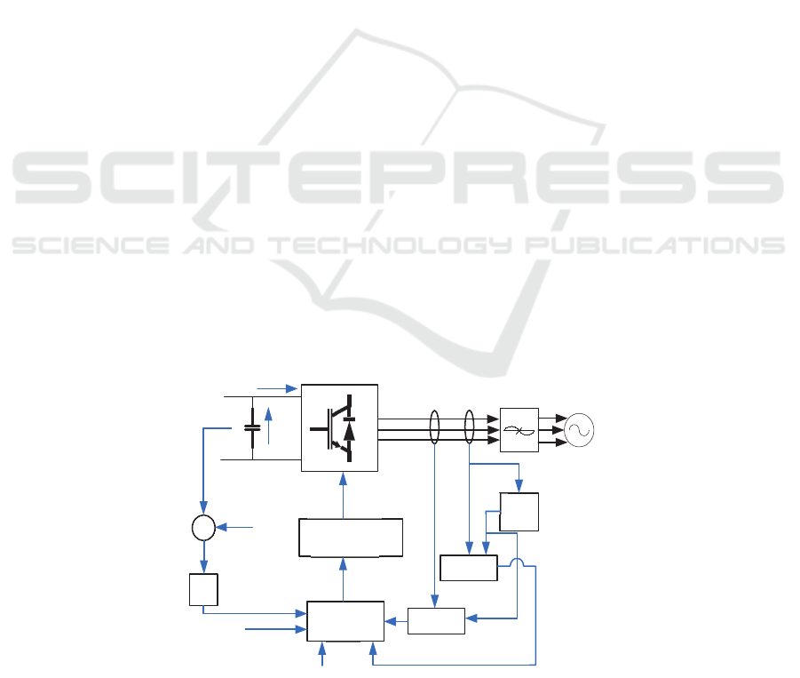
MPC block diagram can be seen in Figure 1:
Figure 1: above is a setting using FCS MPC by
utilizing the optimization of the cost function from
the calculation between the reference and the current
prediction. The cost function equation can be shown
in the equation below:
𝑔𝑖
∗
𝑘1
𝑖
𝒑
𝑘1
𝑖
∗
𝑘1
𝑖
𝒑
𝑘1
(1)
Figure 1: Block Diagram System FCS MPC.
𝑣
𝑖
Inverter
DC/AC
Filter
Grid
𝑣
𝑣
∗
𝑒
𝑖
∗
𝑖
∗
𝑣
𝑣
𝑖
𝑖
𝑘 1
𝑆
PI
Cost Function
Optimization
P
redictive
M
ode
l
P
LL
abc/dq
abc/dq
𝜃
An Improved Hysteresis Band based FCS MPC for Grid-connected Three Phase Inverter
749

Where 𝑖
𝒑
𝑘1
and 𝑖
𝒑
𝑘1
is part of the real
and imaginary in the prediction model. 𝑖
∗
𝑘1
and
𝑖
∗
𝑘1
is the current reference. The output signal
from the inverter corresponds to the generated DC
voltage and the state of the switching signal 𝑆
,𝑆
and 𝑆
. The converter uses a two-level converter in
which there are 6 sectors and 8 vectors following the
equation below:
𝑆
1 𝑗𝑖𝑘𝑎 𝑡𝑜𝑝 𝑠𝑤𝑖𝑡𝑐ℎ 𝑚𝑒𝑛𝑖𝑛𝑔𝑔𝑎𝑙𝑘𝑎𝑛 𝑡ℎ 𝑖𝑠 𝑂𝑁
0 𝑗𝑖𝑘𝑎 𝑏𝑜𝑡𝑡𝑜𝑚 𝑠𝑤𝑖𝑡𝑐ℎ 𝑚𝑒𝑛𝑖𝑛𝑔𝑔𝑎𝑙𝑘𝑎𝑛 𝑡ℎ 𝑖𝑠 𝑂𝐹𝐹
The value at the output voltage is defined as
𝑣
𝑆
𝑣
𝑣
𝑆
𝑣
𝑣
𝑆
𝑣
(2)
Where 𝑣
is a DC voltage source. Taking into
account the unitary vector 𝑎𝑒
/
𝑗
3/2
which represents a phase shift of 120°, The
output voltage on the grid can be defined as
𝑣
2
3
𝑣
𝒂𝑣
𝒂
𝟐
𝑣
(3)
Where 𝑣
,𝑣
and 𝑣
are the phase-to-neutral
(N) voltages in the inverter. The possible
combinations of the gate signal in the inverter,
namely 𝑆
,𝑆
and 𝑆
, there are eight possible
according to the table below
Table 1: Switching States Voltage Vector.
𝑆
𝑆
𝑆
Voltage Vector v
0 0 0
v
0
1 0 0
v
2
3
𝑣
1 1 0
v
1
3
𝑣
𝑗
√
3
3
𝑣
0 1 0
v
1
3
𝑣
𝑗
√
3
3
𝑣
0 1 1
v
2
3
𝑣
0 0 1
v
1
3
𝑣
𝑗
√
3
3
𝑣
1 0 1
v
1
3
𝑣
𝑗
√
3
3
𝑣
1 1 1
v
0
Figure 2: voltage with real and imaginary axes.
2.2 Grid Model
The three-phase axis with the X and Y coordinate
systems showing the fixed axis and the rotating axis.
The mathematical model on the grid will be shown in
the image and equation below.
x
y
a
b
c
Figure 3: Grid Model.
𝑣
𝑣
cos
𝜔.𝑡
(4)
𝑣
𝑣
cos𝜔.𝑡
2𝜋
3
(5)
𝑣
𝑣
cos𝜔.𝑡
4𝜋
3
(6)
Where 𝑣
is the amplitude at the phase voltage
and is the angular frequency. The three-phase
currents in this system are shown in the following
equation:
𝑖
𝑖
cos
𝜔.𝑡 𝜑
(7)
v
→𝑔
v
→𝑔
v
,
→𝑔
,
v
→𝑔
v
→𝑔
v
→𝑔
v
→𝑔
Re
lm
iCAST-ES 2021 - International Conference on Applied Science and Technology on Engineering Science
750
𝑖
𝑖
cos𝜔.𝑡
2𝜋
3
𝜑
(8)
𝑖
𝑖
cos
𝜔.𝑡
4𝜋
3
𝜑
(9)
Where 𝑖
is the amplitude of the phase current
and is the phase voltage and current. From the
symmetrical form, the line-to-line voltage can be
defined as
This section must be in one column.
𝑣
𝑣
𝑣
(10)
𝑣
𝑣
𝑣
(11)
𝑣
𝑣
𝑣
(12)
The number of neutrals at current 𝑖
is
𝑖
𝑖
𝑖
𝑖
(13)
In the case of the neutral current balance is zero
(𝑖
0) then the above equation can be simplified to:
𝑖
𝑖
𝑖
0
(14)
𝑣
𝑣
𝑣
0
(15)
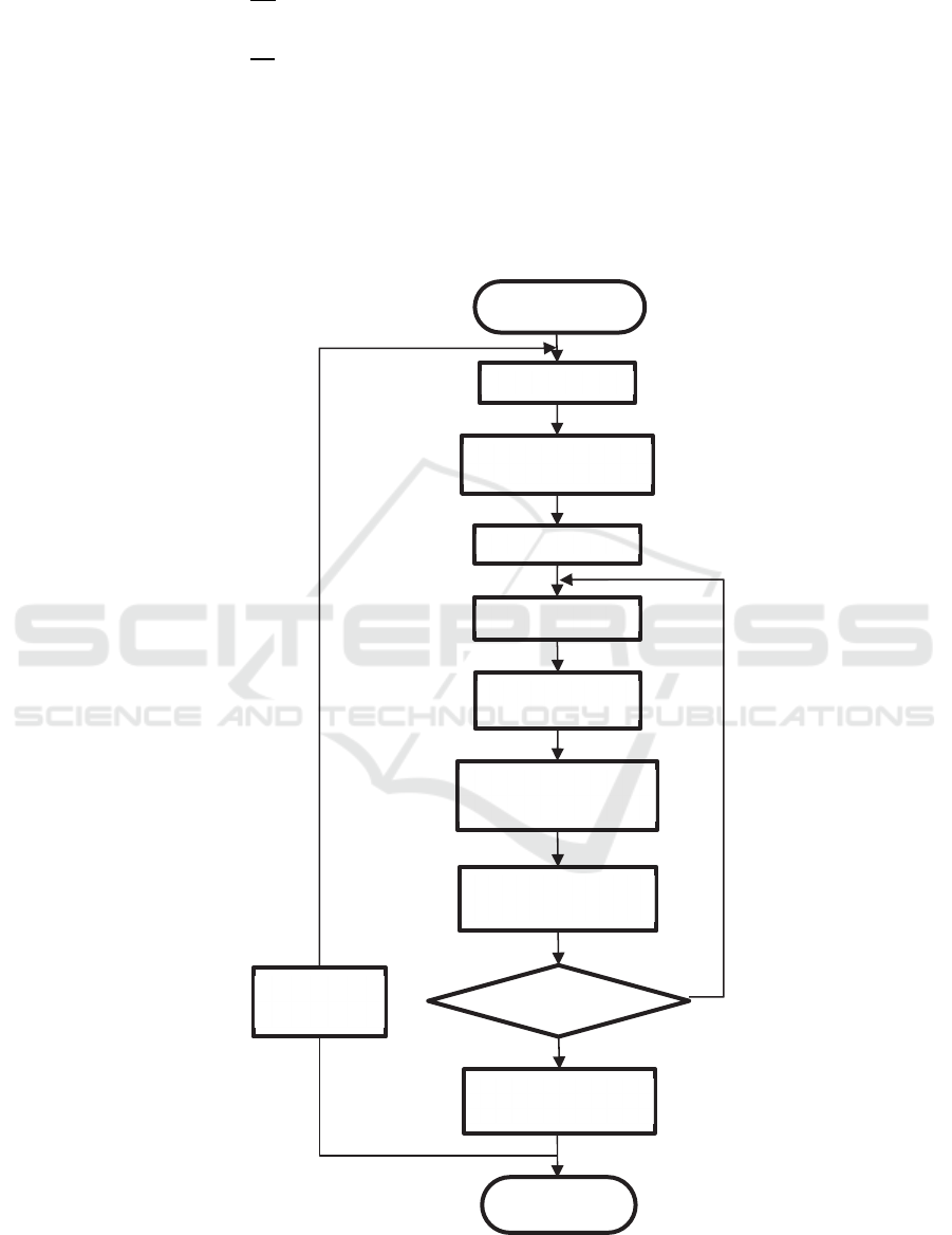
Figure 4: Flow Diagram Implementation FCS MPC.
Startup
Measure i(k)
Back Emf estimation
(
e
q
.23
)
g
o
p
t = inf
𝑥𝑥1
Predictive
model
(
e
q
.16-21
)
Hysteresis Current
Controller (eq.22)
Evaluation cost
function(eq.1)
g
<
g
o
pt
Optimal vector v(k)
end
Next
sampling
An Improved Hysteresis Band based FCS MPC for Grid-connected Three Phase Inverter
751
The power flow in the grid converter can be
controlled by improving the DC-link voltage with a
constant limit.
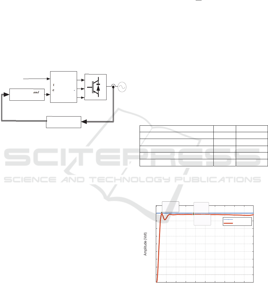
3 PROPOSED SYSTEM
The model that will be implemented in this study is
as shown in the image below, for determining the cost
function, following equation (1). The following is an
explanation for predicting the incoming current and
providing a hysteresis band before entering the cost
function
Figure 5: Block Diagram Proposed System.
The reference current for short time (K+1) in the
current prediction block is following the equation
below in equations (16) and (17) while the current
(k+2) in equations (18) and (19). In addition to the
current reference, the current prediction current (k+1)
is shown in equations (20) and (21)
𝑖
∗
𝑘1
3𝑖
∗
𝑘
3𝑖
∗
𝑘1
3𝑖
∗
𝑘2
(16)
𝑖
∗
𝑘1
3𝑖
∗
𝑘
3𝑖
∗
𝑘1
3𝑖
∗
𝑘2
(17)
𝑖
∗
𝑘2
3𝑖
∗
𝑘1
3𝑖
∗
𝑘
3𝑖
∗
𝑘1
(18)
𝑖
∗
𝑘2
3𝑖
∗
𝑘1
3𝑖
∗
𝑘
3𝑖
∗
𝑘1
(19)
𝑖
𝑘1
3𝑖
𝑘
3𝑖
𝑘1
3𝑖
𝑘2
(20)
𝑖
𝑘1
3𝑖
𝑘
3𝑖
𝑘1
3𝑖
𝑘2
(21)
After knowing the current prediction, the use of
Hysteresis Current Controller is a comparison
between the current prediction and the previous
current and by giving a band of 0.2 bands. The
equation for determining the band before entering
into optimization is
𝑖
𝑖
𝑖
(22)
The optimization used is to determine a vector that
is truly optimal. To obtain the optimal vector, it is
assumed that the input to the grid is a sinusoidal wave
with a fixed amplitude and a fixed frequency. Vector
can be seen from the equation below:
v
𝑅𝑖𝐿
𝑑𝑖
𝑑𝑡
e
(23)
where v is the vector voltage generated from the
inverter, 𝑖 is the current flowing to the grid and e is
the vector for the back emf. All switching states at
𝑣𝑘 with current current 𝑖𝑘 are compared with
subsequent current 𝑖𝑘1 with estimates at
𝑖
𝑘 1.
4 SIMULATION RESULT
Matlab/Simulink programming is used to
demonstrate the application using the FCS MPC
method. The simulation results obtained with
parameters such as the following table:
Table 2: System Parameter.
Parameter Unit Value
DC Voltage 𝑣
900 V
Converter Side Inductor 𝐿
20 mH
Grid Side Inductor 𝐿
1.6 mH
Filter Capacitor 𝐶 65.25 𝜇𝐹
Capacitor Resistance 𝑅
5Ω
The first simulation result is to know the 𝑣
on
the converter system. 𝑣
affects the result of the
generated system.
Figure 6: 𝑉
.
Figure 6: above is a 𝑣
response with a generated
or reference voltage of 900 𝑉𝑜𝑙𝑡𝑠, the voltage read is
882.7 𝑉𝑜𝑙𝑡𝑠. In the picture there is a steady state error
of 18 𝑉𝑜𝑙𝑡𝑠 or 2%. The power demand from the DC
0 0.02 0.04 0.06 0.08 0.1 0.12 0.14 0.16 0.18
Time (s)
0
100
200
300
400
500
600
700
800
900
1000
Vdc
Refferensi
Actual Current
X
0.01056
Y
909.5
X
0.0756
Y
900
X
0.07591
Y
882.7
Optimalisation
of cost function
Hysteresis Band
Current Controller
Predictive
Model
𝑠
𝑠
𝑠
𝑖
∗
𝑘
𝑖
𝑘 1
𝑖
iCAST-ES 2021 - International Conference on Applied Science and Technology on Engineering Science
752
Link input is very influential for the process in the
converter system.
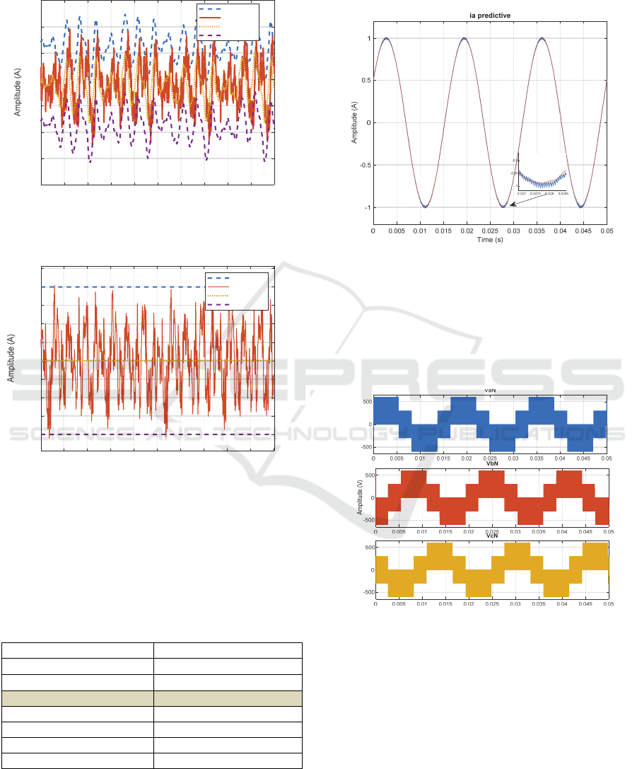
Figure 7: Response 𝑖
actual and 𝑖
𝑟𝑒𝑓𝑓.
Figure 8: Response 𝑖
actual and 𝑖
𝑟𝑒𝑓𝑓.
Figure: 7 and 8 above are currents from 𝑖
then
enter the range of the upper and lower bands on the
hysteresis band. The use of the hysteresis band on 𝑖
here is to get the optimal value before entering the
switching system and getting the cost function value.
Table 3: Cost Function.
Volta
g
e vecto
r
Cost function
v
,v
𝑔
,
0,55
v
𝑔
0,76
v
𝑔
0,47
v
𝑔
0,65
v
𝑔
1,27
v
𝑔
1,45
v
𝑔
0,37
In the table above, the vector 𝑔
0.47 is said to
be the lowest value or optimal value for the cost
function. There are 8 voltage vectors that produce
current to get the cost function value. The lowest
value 𝑔
0.47 above is the value that will be used
in the inverter.
Figure 9: 𝑖
Predictive.
In Figure 9 above, there are still ripples generated
from back emf or caused by dynamic loads. The result
of the flow above is an evaluation of the value of the
cost function. The value of the cost function will be
processed on switching on the inverter.
Figure 10: 𝑣
,𝑣
and 𝑣
output inverter.
Specialization for implementation on FCS MPC
using Two levels. Figure 10 above is the result of
switching generated by the converter obtained from
the cost function. The generated voltage is 600 Volts.
The above wave is not pure sine but the result of some
switching obtained. After getting the sine signal, the
LC filter is given to make it a pure sine signal.
0 0.02 0.04 0.06 0.08 0.1 0.12 0.14 0.16 0.18 0.2
Time (s)
0.96
0.97
0.98
0.99
1
1.01
1.02
1.03
Hysteresis Id idref
Upper Band
id actual
id ref
Lower Band
0.02 0.04 0.06 0.08 0.1 0.12 0.14 0.16 0.18 0.2
Time (s)
-0.02
-0.015
-0.01
-0.005
0
0.005
0.01
0.015
0.02
0.025
Hyesteresis Iq Iq ref
Upper Band
iq
iq ref
Lower Band
An Improved Hysteresis Band based FCS MPC for Grid-connected Three Phase Inverter
753

Figure 11: 𝑣
Output Grid.
The picture above is the final result of this
research which is obtained from the filter and will be
inserted into the transformer to be processed into the
grid system or for use. The generated voltage
amplitude is 600 Volts.
5 CONCLUSIONS
The FCS MPC which is implemented in the inverter
is successfully used by obtaining the cost function.
This system can be implemented on a renewable
energy system in the form of wind, sunlight from a
DC source or an AC source. This optimization
renewable energy technology can be applied. The
power demand from the DC Link input is very
influential for the process in the converter system, the
system can run well starting from the input dc voltage
of 882.7 volts with a steady state error of 2%. The 𝑖
current is processed to produce an optimal current by
utilizing the hysteresis band of 0.2 band. On
switching on the inverter, the second vector voltage
or 𝑔
is 0.47 vector value which is used for switching
on the inverter. FCS MPC can be applied to a two
level converter system, the results obtained are a
voltage of 600 volts. The need for a filter circuit to
produce a sine wave like a pure sine wave generated
by a generator.
ACKNOWLEDGEMENTS
The author acknowledgements State Polytechnic of
Cilacap for supporting the author’s internal research
with the DIPA funding. The author thanks
colleagues who support and assist research directly.
REFERENCES
Ali, M., Haitao, Y., Yao, W., & Yilin, Y. (2021). Control
of linear generator based on hysteresis‐SVPWM
current rectification and bidirectional buck/boost
converter used for energy storage. IET Renewable
Power Generation.
Gendrin, M., Gauthier, J. Y., & Lin-Shi, X. (2016). A
predictive hybrid pulse-width-modulation technique for
active-front-end rectifiers. IEEE Transactions on
Power Electronics, 32(7), 5487-5496.
Guo, L., Zhang, X., Yang, S., Xie, Z., Wang, L., & Cao, R.
(2017). Simplified model predictive direct torque
control method without weighting factors for
permanent magnet synchronous generator-based wind
power system. IET Electric Power Applications, 11(5),
793-804.
iesr. (2019, December 24). Catatan Akhir Tahun: Energi
Terbarukan Masih Terseok - IESR. IESR.
https://iesr.or.id/catatan-akhir-tahun-energi-
terbarukan-masih-terseok
Lyu, J., Ma, B., Yan, H., Ji, Z., & Ding, J. (2020). A
Modified Finite Control Set Model Predictive Control
for 3L− NPC Grid− Connected Inverters Using Virtual
Voltage Vectors. Journal of Electrical Engineering &
Technology, 15(1), 121-133.
Purnata, H., Rameli, M., & Effendie, A. R. (2017, August).
Speed control of three phase induction motor using
method hysteresis space vector pulse width modulation.
In 2017 International Seminar on Intelligent
Technology and Its Applications (ISITIA) (pp. 199-
204). IEEE.
Rodriguez, J., & Cortes, P. (2012). Predictive control of
power converters and electrical drives (Vol. 40). John
Wiley & Sons.
Rodriguez, J., & Cortes, P. (2012). Predictive control of
power converters and electrical drives (Vol. 40). John
Wiley & Sons.
SEKRETARIAT JENDERAL DEWAN ENERGI
NASIOANAL K OUTL OO. (n.d.).
https://www.esdm.go.id/assets/media/content/content-
outlook-energi-indonesia-2017-bahasa-indonesia-.pdf
Tarisciotti, L., Zanchetta, P., Watson, A., Bifaretti, S., &
Clare, J. C. (2014). Modulated model predictive control
for a seven-level cascaded H-bridge back-to-back
converter. IEEE Transactions on industrial
electronics, 61(10), 5375-5383.
Tarisciotti, L., Zanchetta, P., Watson, A., Clare, J. C.,
Degano, M., & Bifaretti, S. (2014). Modulated model
predictive control for a three-phase active
rectifier. IEEE Transactions on Industry
Applications, 51(2), 1610-1620.
Vazqez, S., Marquez, A., Aguilera, R., Quevedo, D., Leon,
J. I., & Franquelo, L. G. (2014). Predictive optimal
switching sequence direct power control for grid-
connected power converters. IEEE Transactions on
Industrial Electronics, 62(4), 2010-2020.
Wang, L., Chai, S., Yoo, D., Gan, L., & Ng, K. (2015). PID
and predictive control of electrical drives and power
0 0.01 0.02 0.03 0.04 0.05 0.06
Time (s)
-600
-400
-200
0
200
400
600
Vabc
Va
Vb
Vc
iCAST-ES 2021 - International Conference on Applied Science and Technology on Engineering Science
754

converters using MATLAB/Simulink. John Wiley &
Sons.
Yang, Y., Wen, H., & Li, D. (2017). A fast and fixed
switching frequency model predictive control with
delay compensation for three-phase inverters. IEEE
Access, 5, 17904-17913.
Zhang, Y., Wu, X., Yuan, X., Wang, Y., & Dai, P. (2016).
Fast model predictive control for multilevel cascaded
H-bridge STATCOM with polynomial computation
time. IEEE Transactions on Industrial
Electronics, 63(8), 5231-5243.
Zhang, Z., Fang, H., Gao, F., Rodríguez, J., & Kennel, R.
(2017). Multiple-vector model predictive power control
for grid-tied wind turbine system with enhanced steady-
state control performance. IEEE Transactions on
Industrial Electronics, 64(8), 6287-6298.
An Improved Hysteresis Band based FCS MPC for Grid-connected Three Phase Inverter
755
