
Design and Implementation of Zeta Converter for Solar Charger
using Fuzzy Logic Controller
Anissa Fahira Azis, Indhana Sudiharto and Ony Asrarul Qudsi
Department of Electrical Engineering, Politeknik Elektronika Negeri Surabaya, Jl. Raya ITS, Surabaya, Indonesia
Keywords
:
Solar Charger, PV, Zeta Converter, Fuzzy Logic Controller.
Abstract
:
In this paper discusses detail design of Zeta converter as battery charging with fuzzy logic control using a
Photovoltaic (PV) source. The voltage generated by the PV is unstable, a DC-DC converter is needed to
regulate the input voltage to the battery. In this paper proposed a zeta converter to increase or decrease the
voltage so output voltage stable for battery charging. Zeta converter is expected to reduce ripples in the
output voltage and minimize voltage disturbances during switching. In this paper, the control method used is
the Fuzzy Logic Controller (FLC). Fuzzy Logic Controller is effective for voltage control which is expected
to produce a stable output of Zeta converter. The concept of battery charging so that the battery can be
charged properly is using the constant voltage method, which is the method of charging the battery with a
constant flowing voltage. The results of the calculation of energy conversion from solar panels to this
proposed design require battery energy storage of 12 V / 20 AH. So, it is necessary to set the battery
charging voltage 120% of the nominal battery voltage. Based on simulation result, the proposed method can
maintain the output voltage according to the setting point for battery charging 14.4 volt so that the proposed
method can be used as a solar charger.
1
INTRODUCTION
Solar energy is one of the renewable energy sources
that has been widely developed in recent years.
Photovoltaic (PV) modules are components that can
convert energy obtained from the sun into electrical
energy in the form of DC voltage. The electrical
energy produced by PV can be used directly or stored
in batteries. Utilization of batteries for solar energy
storage must pay attention to the charging voltage
used. In the battery charging technique with the
Constant Voltage (CV) method, the charging voltage
used ranges from 110% - 130% of the nominal battery
voltage (Wu and Hu, 2016); (Forest et al., 2017);
(Liu and Makaran, 2009).
Many types of converters can be used as battery
chargers (Kumar and Jain, 2013); (Han et al., 2018);
(Patnaik et al., 2018). Buck Converter is a type of
converter that can lower the DC voltage (Ismail et
al., 2010). This
converter can be used if the input
voltage is higher
than the battery charge voltage.
While the Boost
Converter is a type of converter
that can increase the
DC voltage (Bendaoud et al.,
2017). These two types of converters are
not
suitable if implemented for solar chargers (Gao et al.,
2019).For the implementation of the solar charger, a
converter is used that can increase and decrease the
voltage, because the output voltage of PV is very
volatile and depends on sunlight conditions. Buck-
Boost Converter is a converter that is usually used for
solar chargers (Banaei and Bonab, 2019).
However, the resulting voltage
ripple is large
enough that it will affect the efficiency
of the solar
charger. The output voltage generated
from this
converter also has a reverse polarity. So, in
this
study, it is proposed to use Zeta Converter as a
solar charger.
Zeta Converter can work like a Buck-Boost
Converter, which can increase or decrease the
incoming DC voltage based on the amount of PWM
duty cycle ignited in the switching components. Zeta
Converter has better performance than Buck-Boost
Converter (Zhu et al., 2020); (Murthy-Bellur et al.,
2010); (Sunarno et al., 2019). Zeta converter is the
development
of the buck boost converter by
producing a low output
voltage ripple and the
polarity is the same with the
input voltage polarity
of the converter. To maintain
the output voltage
from the Zeta Converter to match
the battery
charging voltage setting point, a Fuzzy
Logic
Azis, A., Sudiharto, I. and Qudsi, O.
Design and Implementation of Zeta Converter for Solar Charger using Fuzzy Logic Controller.
DOI: 10.5220/0010952400003260
In Proceedings of the 4th International Conference on Applied Science and Technology on Engineering Science (iCAST-ES 2021), pages 733-739
ISBN: 978-989-758-615-6; ISSN: 2975-8246
Copyright
c
2023 by SCITEPRESS – Science and Technology Publications, Lda. Under CC license (CC BY-NC-ND 4.0)
733
Controller is used.
Fuzzy Logic Control (FLC) is one of the system
control methods that is currently widely used. This is
one of the advantages of FLC so that the controller
design is easier to do by relying only on logical rules
(Ismail et al., 2010); (Bendaoud et al., 2017); (Ofoli
and Rubaai, 2006). In this study, FLC is used to
regulate the amount of PWM duty cycle that will be
ignited in the
switching component. So that the
proposed method
can produce a stable Zeta
Converter output voltage
with a fluctuating PV
input voltage.
2
SYSTEM DESCRIPTION
One of the dc-dc converters that can be used to adjust
the voltage on the solar panels to produce maximum
power on the solar panels is the zeta converter. When
the voltage on the PV is less than 18.2 V, the
converter will work by adjusting the duty cycle and
increasing the voltage to produce a stable 14.4 V with
fuzzy logic controller. When the voltage on the PV is
greater than 18.2 V, the converter will adjust the duty
cycle and lower the voltage.
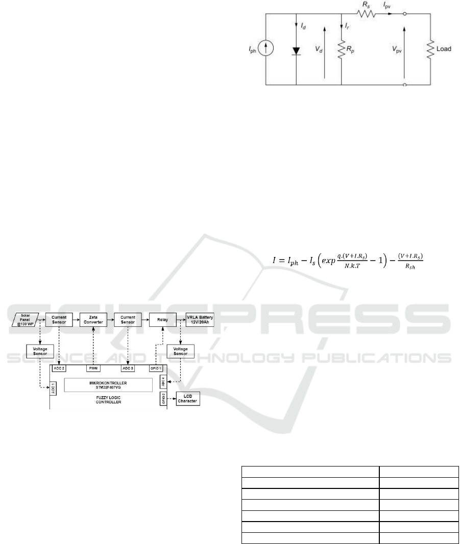
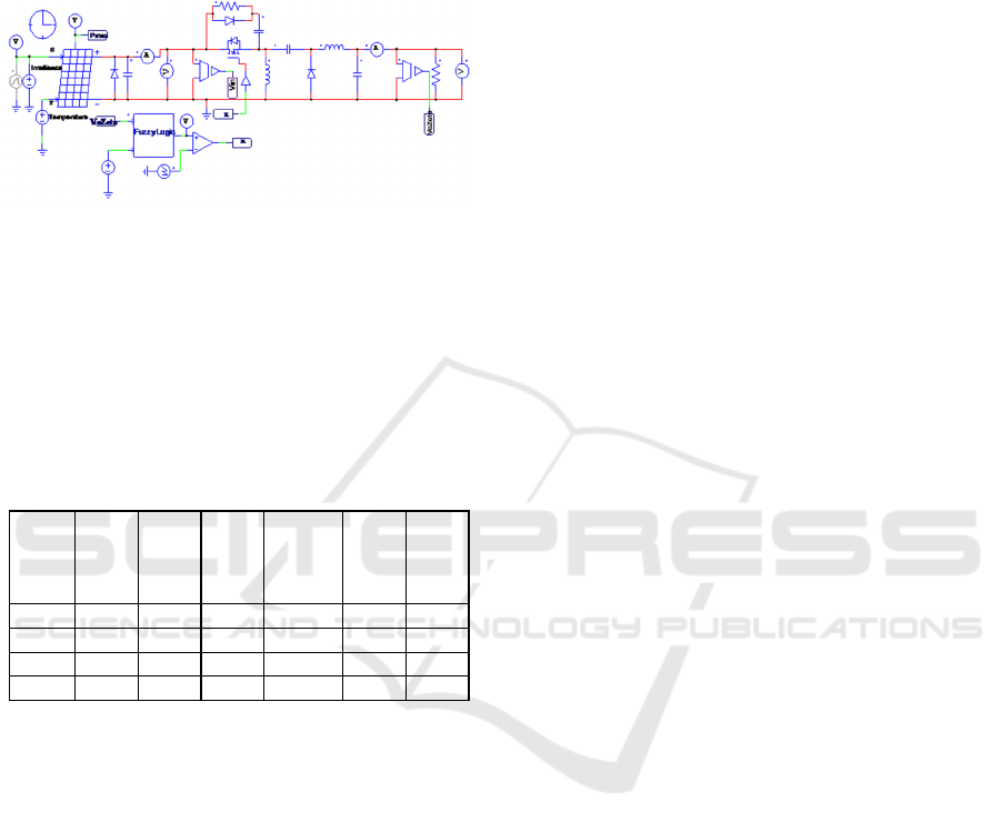
Figure 1: Design block diagram of the system.
The topology of the zeta converter battery
charging system used is shown in Fig. 1. The system
input is a PV with a maximum power capacity of 100
WP. During the simulation, the values of irradiance
and temperature are changed to find out how the
response generated by the zeta converter.
2.1 Solar Panel
Solar panels will convert the absorbed solar energy
into DC electrical energy voltage. Solar panels of
photovoltaic, which produces electrical energy from
light intensity. The working process of solar panels
begins when sunlight is captured by the PV and
Figure 2: Equivalent circuit of PV module.
absorbed by p and n type semiconductor materials
(p- n junction semiconductor) resulting in the release
of electrons. Things that affect the amount of power
produced by
PV are light intensity (irradiation) and
temperature of
the PV module. This semiconductor
consists of
atomic bonds in which there are electrons
as the basic
constituent. Large power of photovoltaic
is expressed
in Watt peak (WP). The equivalent
circuit of
photovoltaic can be shown in Fig. 2.
The
mathematical equation for the PV module
can be
expressed as:
(1)
Where,
𝐼
𝑝𝑣
= output power pv module (A)
𝐼
𝑝ℎ
= generated current (A)
𝐼
𝑠
= saturation reverse current (A)
𝑞
= electron charge (1.6 × 10
−9
𝐶)
𝑉
= output voltage PV (V)
𝑅
𝑠
= series resistance (Ω)
𝑅
𝑠ℎ
= shunt resistance (Ω)
𝐾
= Boltzmann constant (1.38 × 10
−23
𝐽/𝐾)
𝑇
= junction temperature in kelvin (K)
𝑁
= ideality factor of diode
The parameters of PV used in this system are
presented in Table 1.
Table 1: Parameters of Solar Panel.
Paramete
r
Value
Maximu
m
Powe
r
(P
max
)
100 W
Current at P
max
(I
max
)
5.47 A
Voltage at P
max
(V
mp
)
18.2 V
Short Circuit Current (I
sc
)
5.91 A
Open Circuit Voltage (V
oc) 22.5 V
Maximum Syste
m
Voltage 1000 V
2.2 Zeta Converter
Zeta converter is a fourth-order DC-DC converter
made up of two inductors and two capacitors and
capable of operating in either step-up or step-down
mode. The Zeta converter works like a buck-boost,
which can increase or decrease the incoming DC
iCAST-ES 2021 - International Conference on Applied Science and Technology on Engineering Science
734
voltage based on the size of the PWM duty cycle that
is ignited in the switching component. The polarity
between the input and output voltages is the same and
also has two operating stages in one period. The first
stage is when the switch (MOSFET) is on and the
others off. This converter consists of two inductors L1
and L2 and two capacitors C1 and C2, a switch
(MOSFET), and a resistive load. The output of the
zeta converter has a small ripple. Equivalent circuit of
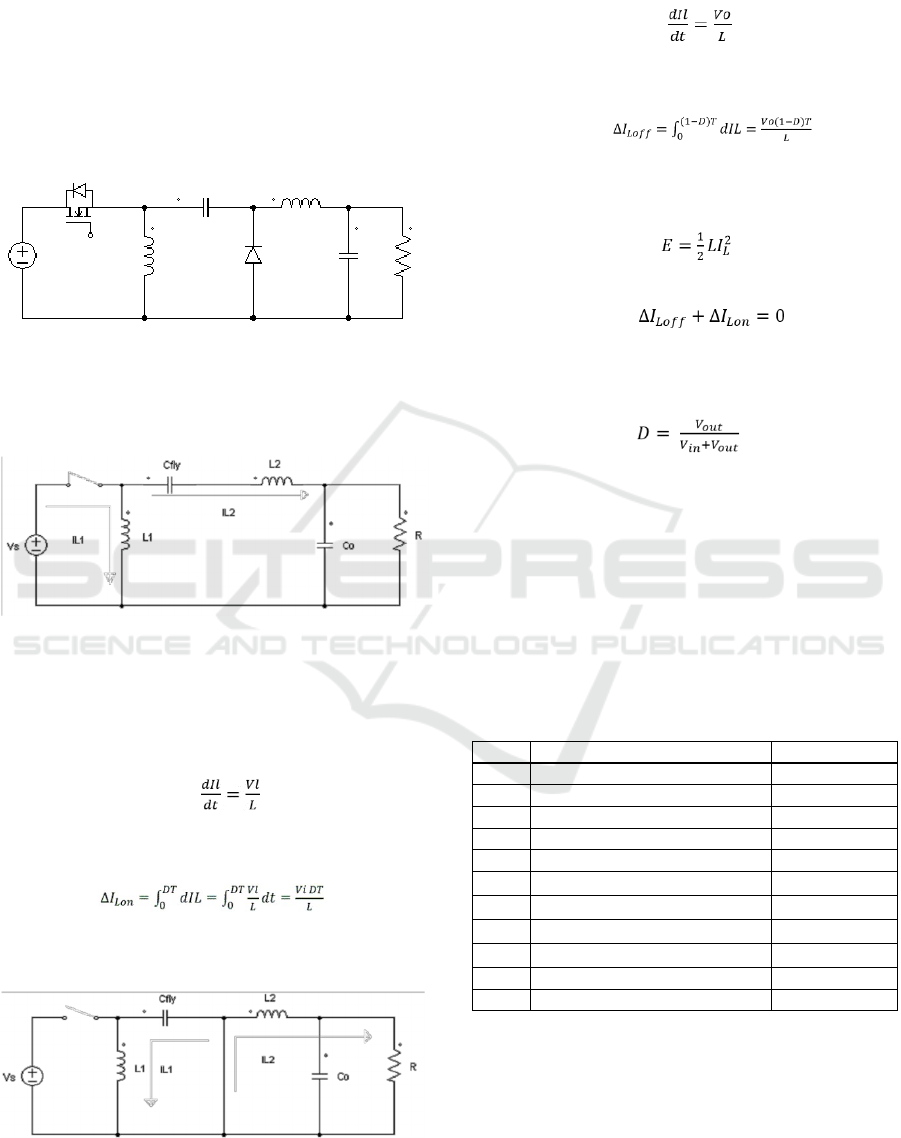
zeta converter as shown in Fig. 3.
Figure 3: Equivalent circuit of Zeta Converter.
It is having two operating modes with respect to ON
and OFF condition of switch zeta converter. In mode
1 switch closed condition is shown in Fig. 4.
Figure 4: Mode 1.
When switch closed (ON) inductors L1 and L2 are
charged and work at t
on
start from t=0 until t=DT, The
mathematical equation for a current in inductor can
be expressed as:
(2)
The value of the inductor current change as the end of
ON condition is
(3)
Then further condition is in mode 2 switch open
(OFF) is shown in Fig.5.
Figure 5: Mode 2.
In the switch is open (OFF), the mathematical
equation for a current inductor can be expressed as:
(4)
That the current changes in when the switch is open
which can be written as
(5)
Energy stored in the inductor must be the same at the
beginning and the end of switching, the formula for
energy in the inductor can be written in equation 6.
(6)
The energy stored must be equal to 0 in each cycle,
(7)
By substitution ∆𝐼
𝐿𝑜𝑛
and∆𝐼
𝐿𝑜𝑓𝑓
, and assuming
100% efficiency, the duty cycle for a zeta
converter operating in CCM is given by,
(8)
Where,
𝑉
𝑖𝑛
= Input voltage (V)
𝑉
𝑜𝑢𝑡
= Output voltage (V)
𝐼𝐿
= The inductor current (A)
𝑇
= Period (s)
𝐷
= Duty cycle (%)
𝐿
= Inductor (H)
The parameter selection for designing
Zeta converter are given in Table 2.
Table 2: Parameter of Zeta Converter.
No Paramete
r
Value
1 Input Voltage 18.2 V
2 Output Voltage 14.4 V
3 Input Current 5.47 A
4 Output Current 3 A
5Dut
y
Cycle 44 %
6 Capacitor C
1
2291
µ
F
7 Capacitor C
2
102.21
µ
F
8 Inductor L
1
212.56
µ
H
9 Inductor L
2
212.56
µ
H
10 Loa
d
Resistance 4.8 Ω
11 Switching Frequenc
y
40 kHz
The waveforms for voltage and current flowing
through the components of the Zeta topology are
shown in Fig. 6.
Design and Implementation of Zeta Converter for Solar Charger using Fuzzy Logic Controller
735
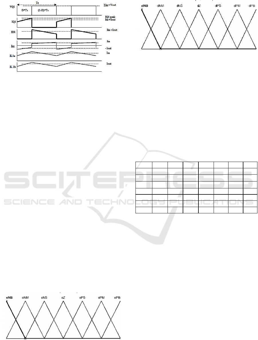
Figure 6: Waveform of current and voltage zeta converter.
2.3 Fuzzy Logic
The characteristic of fuzzy controller can be formed
with a linguistic variable control rule based on the
topology of the converter. To produce an output
constant voltage from the zeta converter according to
the set point, the role of a control is fuzzy logic. The
fuzzy control will adjust the duty cycle output of zeta
to produce an output voltage that matches on 14.4 V.
A fuzzy controller design can be performed in 3 steps.
▪
Step1: Choose fuzzy input and output
variables and their membership functions.
▪
Step2: Express the inference rules linking
input and output variables.
▪
Step3:
Defuzzification of the
output
parameter.
The fuzzy control will compare the detected
output voltage value with the specified set point, that
the “error” and “delta error” values are obtained.
Fuzzy logic with a method used to enter an input to
an output using the if-then equation. The if-then
equation is the rule base of fuzzy logic.
Before making the rule base, enter the fuzzy input
and output fuzzy logic first. Inside the input and
output there is a membership function. The output
membership function value is the duty cycle.
As the fuzzification process there are two inputs
variables, input error and delta-error. The
membership function input error variable is shown in
Fig.7.
Figure 7: Membership function (error).
Figure 8: Membership function (delta-error).
There is also the membership function input delta-
error variable show in Fig.8.
The objective of this journal is to control the
output voltage of zeta converter. The error and delta-
error of the output voltage will be the inputs of fuzzy
logic controller. These two inputs are divided into
seven groups; NB (Negative Big), NM (Negative
Medium), NS (Negative Small), Z (Zero), PS
(Positive Small), PM (Positive Medium), PB
(Positive Big) and its parameter. These fuzzy control
rule base for error and delta-error can be referred in
the table that is shown in Table 3 as below:
Table 3: Rule base of fuzzy logic.
e
/
∆𝑒 NB NM NS Z PS PM PB
NB NB NB NM NM NM NS Z
NM NB NM
NM NM
NS Z PS
NS NM NM
NM
NS Z PS PM
ZNMNMNSZ PS PM PM
PS NM NS Z PS PM PM PM
PM NS Z PS PM PM PM PB
PB Z PS PM PM PM PB PB
The last process is defuzzification process. The
output of the rule base is in the form of fuzzy values.
The defuzzification process is needed to transform a
fuzzy value (linguistic variable) into a value in the
form of a duty cycle which is used to adjust the
switching of the MOSFET converter.
In this strategy, a constant voltage is applied through
battery. The charging current reduces with time until
the battery voltage arrives its default value. In the
experiment, charging is started at (20%) and a
constant voltage is applied on the battery.
The disadvantage of this method is existence of a
huge increment current in the beginning charging
current, which makes this technique hazardous for
charging batteries.
iCAST-ES 2021 - International Conference on Applied Science and Technology on Engineering Science
736
3
SIMULATION RESULT
The topology investigated in PSIM environment in
order to check their behaviour in open loop as well
as close loop configurations. This research is also
being developed in real time using hardware, that the
use of power parameter from each source in this
simulation is adjusted to research on hardware.
3.1 Simulation Model of Zeta Converter
The simulation result of zeta converter open loop
system is shown in Table 4. After being simulated,
the results of zeta converter open loop simulation
shown in Table 4 show that the smallest output
voltage error percentage is 0% and the largest error
value is 0.5 %. One of the data with a duty cycle of
44% with a fixed input voltage 18.2 V, the resulting
output voltage is 14.39 V where the value is close to
the set point. And the output current value is 2.99 A.
In Fig.8, the output voltage waveform in an open loop
produces 14.39 V and the waveform is unstable and
has a ripple voltage.
Table 4: Open loop simulation results.
Duty
Cycle
Vin
(V)
Iin
(A)
Vout
Theory
(
V
)
Vout
(V)
Iout
(A)
%
error
Vo
0.2 18.2 0.24 4.55 4.54 0.94 0.2
0.3 18.2 0.7 7.8 7.79 1.62 0.1
0.4 18.2 1.69 12.13 12.13 2.52 0
0.44 18.2 2.38 14.4 14.39 2.99 0
0.5 18.2 3.8 18.2 18.19 3.79 0.5
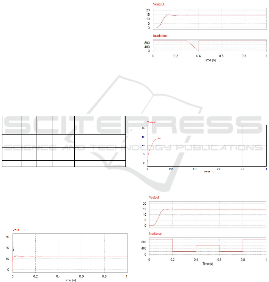
is in Fig.11. The results from a close loop with an
irradiance value is 1000 W/m
2
. The Condition of
irradiance are able to produce a charging voltage of
14.4 volt and the wave results are able to steady state
at conditions in accordance with the set point.
The voltage open loop of zeta converter is
depicted by Fig.9.
Figure 9: Output voltage open loop of zeta converter.
Simulation of zeta converter is carried out before
being given control with a fixed input voltage value
18.2 V and the duty cycle value changes. The
copyright form is located on the authors’ reserved
area.
The zeta converter simulation with fuzzy logic
control as battery charging using simulation on PSIM.
The second simulation is zeta converter integrated
with PV and fuzzy logic control is shown in Fig.10.
Figure 10: Zeta converter close loop simulation circuit
with fuzzy logic controller.
The input source is a PV with a power of 100 WP. A
load used is a resistor with a value according to the
converter calculation which is assumed to be a lead
acid battery. The voltage close loop of zeta converter
Figure 11: Output voltage close loop of zeta converter.
Figure 12: The relationship between voltage and
irradiance.
Fig.12. is the relationship between voltage and
irradiance during conditions close loop system with
fuzzy logic. Can be seen that when given varies
Design and Implementation of Zeta Converter for Solar Charger using Fuzzy Logic Controller
737
irradiance starting from 1000 W/m2 at t=0s to 0.2s,
followed by 200 W/m2 at 0.2s to 0.4s, followed by
600 W/m2 at 0.4s to 0.6s, followed by 200 W/m2at
t=0.6s to 0.8s, and 1000 W/m2 at t=0.8s to 1s. The
output voltage value constant at 14.4 volt.
Figure 13: Output voltage response when disturbed at 0.4s
on the irradiance 1000 W/m
2
.
The result of the output voltage response when
disturbed is shown in Fig.13. The input side of the PV
being disturbed at 0.4 s. When using fuzzy logic
control, the circuit produces a stable output voltage of
14.4 volts. At t=0s to t=1s using the maximum
irradiance is 1000 W/m
2
.
Table 5: Close loop simulation results.
Irrad
iance
(W/
m
2
)
Vin
(V)
Iin
(V)
Vo
Setp
oint
(
V
)
Vo
(V)
Iout
(A)
error
Vo
(%)
1000 19.9 4.1 14.4 14.39 2.99 0.06
800 19.5 4.2 14.4 14.39 2.99 0.06
600 18.8 4.3 14.4 14.39 2.99 0.06
500 18.2 4.4 14.4 14.39 2.99 0.06
Comparison between open loop and close loop in
Table 4 and table 5 shows that the open loop circuit
has a slightly higher voltage deviation. Zeta converter
close loop circuit has lower voltage deviation and has
smaller voltage ripple which can prove that it is a
better performance in controlling voltage with fuzzy
logic for charging battery.
4
CONCLUSIONS
This paper presents design and implementation of
zeta converter for battery charging using fuzzy logic
controller. Based on close loop simulation, the
performance of zeta converter system is able to
produce a stable output voltage of 14.4 volt supplied
by solar panel. Although the irradiance value varies,
fuzzy logic control used 49 rule bases works
according to the design for charging 12 V / 20 Ah lead
acid battery with an output current of 3 A. The fuzzy
logic approach to design a controller for zeta
converter gives a good response output voltage in
simulation. The average error value of the result of
close loop simulation is 0.06 %. Zeta converter is able
to stabilize and regulate the output voltage according
to the desire set point.
REFERENCES
Wu, T. L., & Hu, J. S. (2016, June). Dual-input DC-DC
power converter for solar battery charger. In 2016
IEEE 11th Conference on Industrial Electronics and
Applications (ICIEA) (pp. 1201-1206). IEEE.
Forest, A., Dallard, M., & Shabani, A. (2017, April). An
optimized platform for performance evaluation of solar
battery chargers. In 2017 IEEE 30th Canadian
Conference on Electrical and Computer Engineering
(CCECE) (pp. 1-4). IEEE.
Liu, K., & Makaran, J. (2009, October). Design of a solar
powered battery charger. In 2009 IEEE Electrical
Power & Energy Conference (EPEC) (pp. 1-5). IEEE.
Banaei, M. R., & Bonab, H. A. F. (2019). A high
efficiency nonisolated buck–boost converter based on
ZETA converter. IEEE Transactions on Industrial
Electronics, 67(3), 1991-1998.
Gao, Y., Zhang, X., Cheng, Q., Guo, B., & Yang, J. (2019).
Classification and review of the charging strategies for
commercial lithium-ion batteries. IEEE Access, 7,
43511-43524.
Zhu, B., Liu, G., Zhang, Y., Huang, Y., & Hu, S. (2020).
Single-switch high step-up zeta converter based on
coat circuit. IEEE Access, 9, 5166-5176.
Murthy-Bellur, D., & Kazimierczuk, M. K. (2010).
Isolated two-transistor zeta converter with reduced
transistor voltage stress. IEEE transactions on circuits
and systems II: Express briefs, 58(1), 41-45.
Sunarno, E., Sudiharto, I., Nugraha, S. D., Murdianto, F.
D., & Qudsi, O. A. (2019, November). Design and
implementation bidirectional SEPIC/ZETA converter
using Fuzzy Logic Controller in DC microgrid
application. In Journal of Physics: Conference Series
(Vol. 1367, No. 1, p. 012058). IOP Publishing.
Kumar, L., & Jain, S. (2013). A multiple source DC/DC
converter topology. International Journal of Electrical
Power & Energy Systems, 51, 278-291.
Han, W., Zou, C., Zhou, C., & Zhang, L. (2018).
Estimation of cell SOC evolution and system
performance in module-based battery charge
equalization systems. IEEE Transactions on Smart
Grid, 10(5), 4717-4728.
Patnaik, L., Praneeth, A. V. J. S., & Williamson, S. S.
(2018). A closed-loop constant-temperature constant-
voltage charging technique to reduce charge time of
lithium-ion batteries. IEEE Transactions on Industrial
Electronics, 66(2), 1059-1067.
Ismail, N. N., Musirin, I., Baharom, R., & Johari, D.
(2010, November). Fuzzy logic controller on DC/DC
iCAST-ES 2021 - International Conference on Applied Science and Technology on Engineering Science
738

boost converter. In 2010 IEEE International
Conference on Power and Energy (pp. 661-666).
IEEE.
Bendaoud, K., Krit, S., Kabrane, M., Ouadani, H., Elaskri,
M., Karimi, K., ... & Elmaimouni, L. (2017, May).
Fuzzy logic controller (FLC): Application to control
DC-DC buck converter. In 2017 International
Conference on Engineering & MIS (ICEMIS) (pp. 1-
5). IEEE.
Ofoli, A. R., & Rubaai, A. (2006). Real-time
implementation of a fuzzy logic controller for switch-
mode power-stage DC–DC converters. IEEE
Transactions on Industry Applications, 42(6), 1367-
1374.
Design and Implementation of Zeta Converter for Solar Charger using Fuzzy Logic Controller
739
