
Design and Implementation of Portable and Prospective Embedded
System and IoT Laboratory Kit Modules
Era Madona, Yulastri, Anggara Nasution and M. Irmansyah
Department of Electrical Engineering, Padang State Polytechnic, Jl. Limau Manih Padang, 25164, Indonesia
Keywords:
Laboratory Kit Module, Embedded System, IoT, Portable.
Abstract:
The purpose of this research is design and implementation a new design of a low-cost, portable and
prospective laboratory kit module. Laboratory kits are made easy to assemble, with relatively small
dimensions and suitable for laboratories with limited experimental space and funds. The research stages are
carried out starting with needs analysis, hardware design, software design and overall testing. The test results
of the DHT 11 temperature sensor shows it can read the temperature and humidity index while data in digital
and displayed on the LCD. The PWM of DC motor and the direction of the motor rotation can be controlled
using a push button. The keypad can control the direction of rotation of the servo motor and students are
expected able to provide authentication through a password with a keypad. Testing result of the kit module
for data communication using a local network to get Quality of Service (QOS) with throughput parameters
on the Hypertext Transfer Protocol (HTTP) protocol close to 99.71%. This result include to the category of
good quality network and overall test results of whole system is well. Perhaps this module will encourage
students able to make technological innovation applications based on embedded systems and IoT and lead the
creation of technology among students.
1
INTRODUCTION
Embedded system is a computer system
specifically designed for a specific purpose in order
to improve the function of a machine. The
development of information technology today is
marked by the presence of the Internet of Things
(IoT). IoT is an internet service that is integrated with
the use of certain types of sensors (Ghosh et al.,
2016), (Khan, 2017) Currently, IoT-based embedded
systems have been widely applied such as for health
monitoring (E. Madona et al., 2018), (Yulastri et al.,
2018), natural disasters (E. Madona et al., 2019),
agriculture (Jan Bauer et al., 2018) and the industrial
world (Breivold & Sandstrom, 2015). The ability of
students to apply embedded systems is needed,
especially in the world of working and other things. It
was successfully applied to the Undergraduate
Embedded System Education at Carnegie Mellon
(Koopman et al., 2005). In the academic activity,
many studies have been carried out on the Embedded
system for its development (Mendoza et al., 2016),
implementation of servo motor control (Bual et al.,
2019), use of sensors (Bhadani & Vashisht, 2019) and
DC motors (Sutyasadi & Wicaksono, 2020).
Laboratory practice activities are important
activities
for vocational education related to their
experience in
learning, thinking and solving
problems (Indrianto et
al., 2018). Limited
equipment is a major problem for
students causing
students to not be able to experience
learning.
The learning process is not optimal because of
inadequate laboratory equipment. Computer
simulation is an alternative for these problems
(Anggara et al, 2019) such as LabView (Deaky et al.,
2011), Matlab (Espinosa & Thiel, 2017) and others.
This software uses a license whose budget is not
affordable by the laboratory. The use of plants for
IoT-based industries for learning is impossible
because it is very expensive. In this study, a new
design for a low-cost, portable laboratory kit module
was created for use in embedded systems and data
communication practicum in the Electronic
Engineering Study Program, Electrical Engineering
Department.
Some related researches are study conducted by
(Indrianto et al., 2018) showed an increase in student
learning scores of 7.8% by using the module for
embedded systems practicum activities. Making a
cargo transporting robot (Buditjahjanto et al., 2020)
686
Madona, E., Yulastri, ., Nasution, A. and Irmansyah, M.
Design and Implementation of Portable and Prospective Embedded System and IoT Laboratory Kit Modules.
DOI: 10.5220/0010951100003260
In Proceedings of the 4th International Conference on Applied Science and Technology on Engineering Science (iCAST-ES 2021), pages 686-691
ISBN: 978-989-758-615-6; ISSN: 2975-8246
Copyright
c
2023 by SCITEPRESS – Science and Technology Publications, Lda. Under CC license (CC BY-NC-ND 4.0)
applied it method as a learning medium for
microcontrollers, the results of the study show that the
prototype made can be used in the teaching and
learning process. A similar study was also conducted
by (Ali et al., 2018) making the MCS51
microcontroller practical module which is portable
and lower power consumption. Developments of
previous studies are (1). Practical modules are
integrated in one PCB board with low power
consumption and portable. (2). Integrated with LAN
Modules, Wireless and sensors for Internet of Thing
(IoT) applications. Miniaturization is the contribution
of this research.
The purpose of this research to design and
implementation a new design of a low-cost, portable
and prospective laboratory kit module. Laboratory
kits are made easy to assemble, with relatively small
dimensions and suitable for laboratories with limited
experimental space and funds. This module kit
consists of arduino embedded system modules, mcu
nodes, LAN modules for data communication and
sensors with various features. It is hoped that this
module will encourage students to be able to create
technological innovation applications based on
embedded systems and IoT which will lead to the
creation of technology in between students.
2
METHOD
The learning of Embedded Systems and data
communication (IoT) are needed practical activities,
so students become more understand and have skills
while they graduate. Based on the results of the
analysis, we propose this practicum module to
overcome the previously identified problem, namely
the absence of an Embedded System and data
communication (IoT) practicum module. This
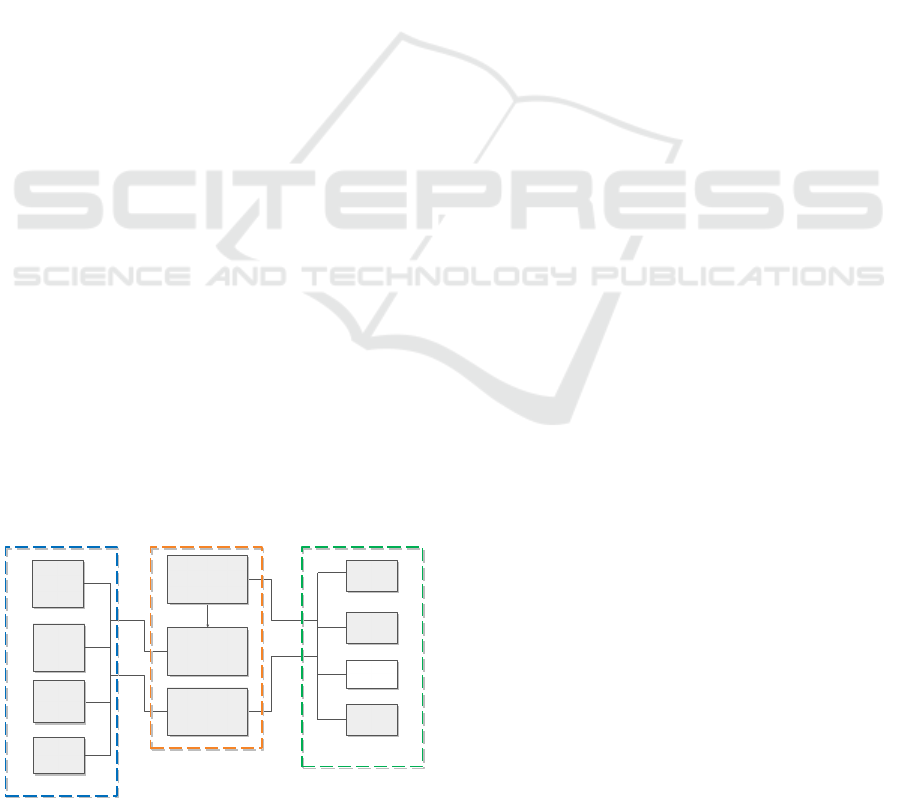
module consists of input block, process block and
output block as shown in Figure 1.
INPUT
CONTROL AND
OUTPUT
COMUNICATION DATA
Figure 1: Block Diagram of the practicum module.
Based on Figure 1, the operation of this
practicum
module is divided into three parts, namely
input,
process and output. Input consists of DHT,
push
button, keypad and browser. DHT11 reads the
temperature and sent the data to the Arduino digital
pin. Browser provides input to Arduino via Ethernet
network and Browser provides input to NodeMCU
via wireless network. Once data receive, it will
processed on the Arduino uno or NodeMCU
according to its use. The using of Arduino is required
if the input only wants to be processed directly to the
output and using Ethernet communication. But if the
system use the wireless feature as an output, it can use
NodeMCU. Furthermore, the data has been processed
by the microcontroller is issued to several available
outputs including LCD, DC Motor, LED and Relay.
The LCD will display characters in the form of text
or numbers. The DC motor works to issue a
movement that can be adjusted via PWM. LED to
display an indicator in the form of light. The relay
works as an automatic switch.
2.1 Design of Embedded System Kit
Module and Data Communication
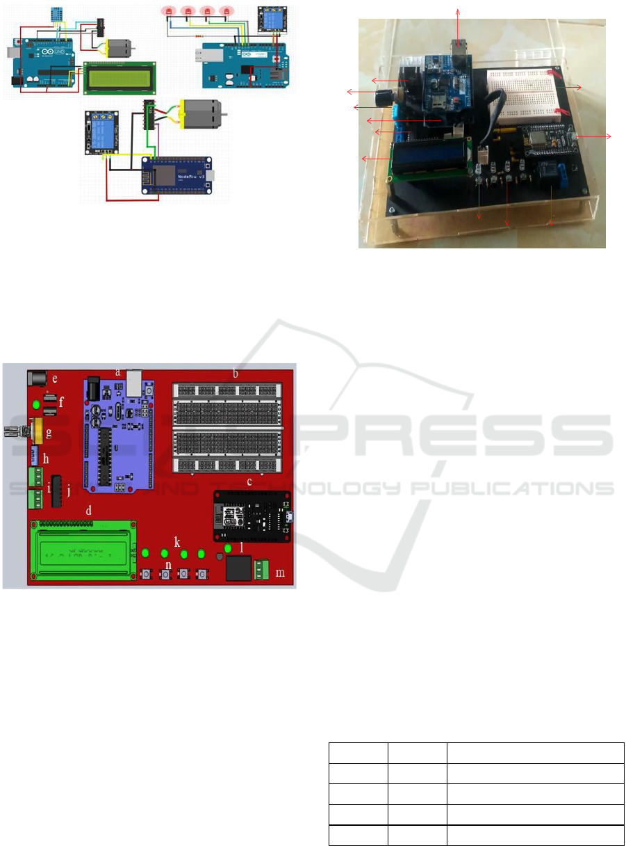
The design process starts with the creation of
the
circuit. This circuit consists of a temperature and
humidity detector using a DHT11 sensor, push
button, LCD, Led, relay and dc motor. DHT11 is
connected to the VCC Pin on the Arduino Uno to
provide an input voltage of 5V, then the DHT 11
GND Pin is connected to the Arduino GND Pin, the
DHT 11 Data Pin is connected to Arduino Pin 2. Then
on the LCD, 4 PINs are used, namely VCC, GND,
SDA and SCL. The VCC and GND pins are
connected to the customized pins on the Arduino, the
SDA Pins are connected to the Analog A4 Pins and
the SCL Pins are connected to the Analog A5 Pins.
Then on the Motor pins that are used only the Positive
Motor and Negative Motors are connected to the
adjusted Pins on the Arduino Pins as shown in figure
2.
In the LED circuit, the LED Pin 1 is connected to
the digital pin 10 on the Arduino Uno and the GND
Pin is connected to the Arduino GND Pin. LED 2 is
connected to digital pin 11 on Arduino Uno and
GND Pin is connected to Arduino GND Pin, LED 3
is connected to digital pin 12 on Arduino Uno and
GND Pin is connected to Arduino GND Pin, Data
Relay pin is connected to digital pin 3.
Ethernet Shield
DHT 11
DC Motor
LCD
push
button
Arduino
LED
Keypad
NodeMCU
Relay
Browser
Design and Implementation of Portable and Prospective Embedded System and IoT Laboratory Kit Modules
687
Powe
r
Supl
y
BreadBoard
Potensio
DHT11
Arduino Uno
Pin
Motor DC
LCD
LED
PushButton
Rela
y
Figure 2: The practical module electronics circuit.
As for DC motor circuit, Data Pin 1 on the DC Motor
is connected to Pin D1 NODEMCU and Data Pin 2 is
connected to pin D2 NODEMCU. The Data Relay pin
is connected to the D0 pin of the NODEMCU and the
VCC and GND pins correspond to the VCC and GND
pins of the NODEMCU. The practical module design
can be seen in Figure 3.
Figure 3: Overall Practicum Module Design.
Caption on picture 3, a) Arduino, b) Bread Board, c)
NODEMCU, d) LCD, e) input voltage, f) Regulator
(7805), g) Potensiometer, h) DHT11, i) Pin out dc
motor, j) IC L293D, k) LED, l) Relay, m) Pin out
relay, n) Push button.
3
RESULT AND ANALYSIS
The next step is testing the practical module, this
test
aims to find out the advantages and disadvantages
of
the system. The test is carried out in two stages.
First, system performance testing and the second
overall module testing. The practical module has been
made is shown in Figure 4.
Ethernet Shield
NodeMCU
Figure 4: Practical module of embedded systems and data
communication.
3.1 Performance Test Modul
Embedded System
Tests carried out starting from testing on the
embedded system then continued with network data
communication. Figures 5a, 5b and 5c are the results
of the performance test of the embedded system
module which consists of an output, input and Analog
Digital Converter (ADC) circuit. The test in this
section begins by creating a program to verify that the
components in the output section are working
properly consisting of LEDs, LCDs, DC motors and
servo motors. On the LCD I2C LCD is used, this
module is controlled serially in sync with the I2C/IIC
protocol (interface). integrated circuit) or TWI (Two
Wire interface) with addresses 0x27 and 0x37. To
control the DC motor, the motor driver IC L293D is
used. The EN1 pin is a pin that is used to enable the
DC motor (ON/OFF DC motor), therefore the EN1
pin is connected to the PWM output of the Arduino
module. While the IN1 and IN2 pins are used as logic
inputs to regulate the rotation of the DC motor and
can also be used to quickly stop the DC motor.
Control is done by push buttons, keypads and buttons
on the browser. The test results can be seen in table 1
Table 1: Motor rotation test.
IN 1 IN 1 Motor Condition
0 0 Stop
0 1 Turn clockwise (CW)
1 0 Turn counterclockwise (CCW)
1 1 Stop
iCAST-ES 2021 - International Conference on Applied Science and Technology on Engineering Science
688
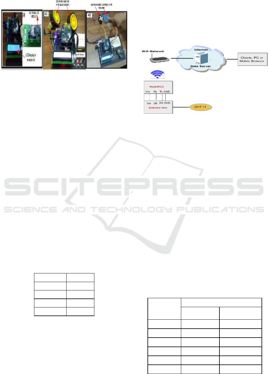
Figure 5: Performance test of the designed module kit: (a)
image of LCD display and I2C module LCD; (b) Picture
of DC motor control with push button; (c) Picture of servo
control with keypad.
The motor rotates clockwise, if the Arduino
module pin Pin 9 (IN1) is given a logic low and Pin10
(IN2) is given a logic high and if you want to rotate
the other way around then the Arduino module pin
Pin 9 (IN1) is given a logic high and Pin 10 (IN2) is
given a logic high. low logic. While EN1 is connected
to the PWM output of the Arduino module (Pin5).
Furthermore, the function test on the input circuit is
carried out The 10K resistor functions as an external
pull-up resistor at the push button input. With the
pull-up resistor, the microcontroller will read logic '1'
when no switch is pressed. Without a pull-up resistor,
the I/O pin will float and the microcontroller can read
it as a logic '1' or '0'. Servo motor with keypad as a
control tool to control the servo motor. The program
loaded into the embedded system module is when
button 2 is pressed the servo motor rotates at position
20
o
, when button 4 is pressed the servo motor rotates
at position 40
o
, when button 9 is pressed the servo
motor rotates at position 90
o
, and when button 0 is
pressed the servo motor rotates at position 0
o
.
Table 2: Servo Motor Program Logic with Keypad as
Control Device.
Keypad Servo
0 0
o
2
20
o
4
40
o
9
90
o
3.2 Performance Test Data
Communication Module
Furthermore, testing the module for data
communication, the object of this test is to implement
temperature monitoring using NodeMCU with a
DHT11 sensor. NodeMCU is used as a wireless
transmission medium while DHT11 is a temperature
and humidity sensor. Testing of objects using a local
network to obtain Quality of Service (QOS) results
with throughput parameters on the Hypertext
Transfer Protocol (HTTP) protocol. The flow of the
testing system can be seen in Figure 6.
Figure 6: Flow of the http protocol-based data
communication module testing system.
The NodeMCU module is a wifi module that is
used to connect the microcontroller to the internet.
This module is based on the ESP8266 serial WiFi
SoC (Single on Chip) with onboard USB to TTL. Pins
D5 (GPIO14) and D6 (GPIO12) as RX and TX where
RX or Data Receiver is connected to digital pin 9 of
the microcontroller, TX pin which is transmitting data
is connected to digital 3 microcontroller then GND
pin is connected to GND of the microcontroller and
VIN pin connected to the Arduino VCC. DHT11
sensor data that has been processed by the
microcontroller is sent via wireless. The data is sent
with the http protocol using port 80. The data is stored
in a database which will then be displayed on a
website that is accessed by the user. The results of
throughput testing using wireshark can be seen in
table 3. Throughput is the effective data transfer rate
measured in bps. Throughput is the total number of
packets, observed successful packet arrivals during a
certain time interval, divided by that time interval
(Taruk & Ashari, 2016).
Table 3: Data Throughput.
Package
Average Byte/sec
Available
throughput
Received
throughput
1 1169,887 1165,887
2 1167,889 1160,973
3 1169,949 1168,936
4 1166,954 1160,96
5 1170,883 1169,889
average 1169,1124 1165,329
Design and Implementation of Portable and Prospective Embedded System and IoT Laboratory Kit Modules
689

Based on table 3, it can be seen that throughput is
used optimally, the average value of throughput
received (1165.329 bps) is close to the overall
throughput value (1169.1124 bps). If the percentage
is then the throughput value is 99.71%. Throughput
data, the network used for testing NodeMCU as a web
client with the http protocol is included in the good
quality network category based on the reference from
the TIPHON table (Wulandari, 2016). Furthermore,
observations and testing of the module as a whole are
carried out from a series of inputs, outputs, sensors
and network-based data communications that are
adapted to student practicum jobs, as shown in table
4.
Table 4: Overall Practicum Module Testing Results.
Practical
Job Expected Observation
and testing
Information
Control
application
with keypad
input, push
button, sensor
Keypad, push
button and
sensor can
control
LED,
LCD,
dc motor and
servo motor
Keypad, push
button and
sensor can
control
LED,
LCD,
dc motor and
servo motor
good
LED
display
application,
DC motors,
LCD and Servo
motors
LED,LCD
can be
displayed and
Servo motor,
DC motor can
rotate
LED,LCD
can be
displayed and
Servo motor,
DC motor can
rotate
good
Web-based
monitoring
system
application
NodeMCU and
Ethernet
can
function as a
webclient
NodeMCU and
Ethernet
can
function as a
webclient
good
Web-based
control
system
application
NodeMCU and
Ethernet
can
function as a
server
NodeMCU and
Ethernet
can
function as a
server
good
From table 4 it can be seen that the tests were carried
out based on student practicum jobs on each input
series, and the output results were that all applications
tested were successful as expected.
4
CONCLUSIONS
In this study, a simple, inexpensive and portable
laboratory kit module was developed for use in
embedded systems and communications practicum.
Test results DHT 11 temperature sensor can read the
index of temperature and humidity whose data is in
the form of digital data and displayed on the LCD.
The PWM of the DC motor and the direction of
rotation of the motor can be controlled using a push
button. The keypad can control the direction of
rotation of the servo motor so that students are
expected to be able to provide authentication through
a password with a keypad. Testing the kit module for
data communication using a local network to obtain
Quality of Service (QOS) results with throughput
parameters on the Hypertext Transfer Protocol
(HTTP) protocol close to 99.71% include to the
category of good quality network. The overall test
results are as expected.
REFERENCES
Ghosh, A. M., Halder, D., & Hossain, S. K. A. (2016).
Remote health monitoring system through IoT. 2016
5th International Conference on Informatics,
Electronics and Vision, ICIEV 2016, 921–926.
Khan, S. F. (2017). Health care monitoring system in
Internet of Things (IoT) by using RFID. 2017 6th
International Conference on Industrial Technology
and Management, ICITM 2017, 198–204.
https://doi.org/10.1109/ICITM.2017.791792 0
E. Madona, M. Irmansyah, and A. Nasution (2018).
Sistem Informasi Untuk Posisi Dan Lama Duduk
Dengan Smartphone Android Berbasis
Mikrokontroler. Elektron J. Ilm., vol. 10, no. 2, pp. 1–
5, 2018, doi: 10.30630/eji.10.2.75.
Yulastri, E. Madona, M. Irmansyah, and A. Nasution
(2020). Alat Deteksi Jatuh Berbiaya Murah Dengan
Tracking Position Untuk Pasien Vertigo dan Sinkop. J.
RESTI (Rekayasa Sist. dan Teknol. Informasi), vol. 4,
no. 6, pp. 9–11, 2020, doi: 10.29207/resti.v4i6.2608.
Madona, M. Irmansyah, and A. Nasution (2019). Design
Dan Implementasi Wireless Sensor Network Pada
Prototype Pendeteksian Material Galodo. vol. 11, pp.
39–42, 2019
Jan Bauer and Nils Aschenbruck (2018). Design and
Implementation of an Agricultural Monitoring System
for Smart Farming. 2018 IoT Vertical and Topical
Summit on Agriculture - Tuscany (IOT Tuscany)
Breivold, H. P., & Sandstrom, K. (2015). Internet of
Things for Industrial Automation-Challenges and
Technical Solutions. Proceedings - 2015 IEEE
International Conference on Data Science and Data
Intensive Systems; 8th IEEE International Conference
Cyber, Physical and Social Computing; 11th IEEE
International Conference on Green Computing and
Communications and 8th IEEE International
Conference on Internet of Things,
DSDIS/CPSCom/GreenCom/IThings 2015, 532–539.
https://doi.org/10.1109/DSDIS.2015.11
Koopman, P., Choset, H., Gandhi, R., Krogh, B.,
Marculescu, D., Narasimhan, P., Paul, J. M.,
iCAST-ES 2021 - International Conference on Applied Science and Technology on Engineering Science
690

Rajkumar, R., Siewiorek, D., Smailagic, A.,
Steenkiste, P., Thomas, D. E., & Wang, C. (2005).
Undergraduate Embedded System Education at
Carnegie Mellon. ACM Transactions on Embedded
Computing Systems, 4(3), 500–528.
https://doi.org/10.1145/1086519.1086522
Bual, C. L. C., Cunanan, R. D., Bedruz, R. A. R.,
Bandala,A., Vicerra, R. R. P., & Dadios, E. P. (2019).
Design of Controller and PWM-enabled DC Motor
Simulation using Proteus 8 for Flipper Track Robot.
2019 IEEE 11th International Conference on
Humanoid, Nanotechnology, Information Technology,
Communication and Control, Environment, and
Management, HNICEM 2019, 1, 1–5. https://doi.org/
10.1109/HNICEM48295.2019.90727 36
Bhadani, P., & Vashisht, V. (2019). Soil moisture,
temperature and humidity measurement using arduino.
Proceedings of the 9th International Conference On
Cloud Computing, Data Science and Engineering,
Confluence 2019, 567–571. https://doi.org/10.1109/
CONFLUENCE.2019.8776 973
Sutyasadi, P., & Wicaksono, M. B. (2020). Joint control of
a robotic arm using particle swarm optimization based
H2/H∞ robust control on arduino. Telkomnika
(Telecommunication Computing Electronics and
Control), 18(2), 1021–1029. https://doi.org/10.12928/
TELKOMNIKA.V18I2.14 749
Indrianto, Susanti, M. N. I., Arianto, R., & Siregar, R. R.
A. (2018). Embedded system practicum module for
increase student comprehension of microcontroller.
Telkomnika (Telecommunication Computing
Electronics and Control), 16(1), 53–60.
https://doi.org/10.12928/TELKOMNIKA.v16i1.419 4
Anggara N. (2019). Penerapan Rangkaian Simulasi
Terintegrasi Untuk Efisiensi Penggunaan. Jurnal
RESTI (Rekayasa Sistem Dan Teknologi Informasi),
1(10), 4–8.
Deaky, B., Lupulescu, N. B., & Ursutiu, D. (2011).
Extended educational use of the Microcontroller
Student Learning Kit (MCU SLK). 2011 IEEE Global
Engineering Education Conference, EDUCON 2011,
913–916. https://doi.org/10.1109/EDUCON.2011.
5773254
Espinosa, H. G., & Thiel, D. V. (2017). MATLAB-Based
interactive tool for teaching electromagnetics
[education corner]. IEEE Antennas and Propagation
Magazine, 59(5), 140–146. https://doi.org/10.1109/
MAP.2017.2731218
Taruk, M., & Ashari, A. (2016). Analisis Throughput
Varian TCP Pada Model Jaringan WiMAX. IJCCS
(Indonesian Journal of Computing and Cybernetics
Systems), 10(2), 115. https://doi.org/10.22146/
ijccs.15529
Wulandari, R. (2016). Analisis QoS (Quality of Service)
Pada Jaringan Internet. Jurnal Teknik Informatika
Dan Sistem Informasi, 2(2), 162–172.
Buditjahjanto, I. G. P. A., Rizqi, C. A., & Suprianto, B.
(2020). Developing robot transporter learning media
to
learn microcontroller. Jurnal Pendidikan Vokasi,
10(3), 270–281. https://doi.org/10.21831/
jpv.v10i3.34140
Ali, L., Rahman, L., & Akhter, S. (2018). Module-based
Edukit for teaching and learning 8051
microcontroller programming. 2nd IEEE
International Conference on Telecommunications
and Photonics, ICTP 2017, 2017-Decem(December),
57–61. https://doi.org/10.1109/ICTP.2017.8285918
Mendoza ‐ Sánchez, B., & Gogotsi, Y. (2016). Synthesis
of two‐dimensional materials for capacitive energy
storage. Advanced Materials, 28(29), 6104-6135.
Design and Implementation of Portable and Prospective Embedded System and IoT Laboratory Kit Modules
691
