
Experimental Study on the Effect of Intercooler on a Compressor
Performance on Multistage Type Cold-storage Simulation
I P. S. Negara
a
and I M. Arsawan
b
Department of Mechanical Engineering, Politeknik Negeri Bali Badung Bali, Indonesia
Keywords: Intercooler, Compressor Work and Performance.
Abstract: Multistage type cold storage is a refrigeration machine required in an industry because it functions to store
food products for a long time. Bali, as a world tourist destination, will rely heavily on this cooling system in
preparing services for tourists, especially in the food and beverage sector. Multistage type cold storage is
designed to reach the evaporator temperature below -30ºC thus the used compressor performance must be
able to produce maximum refrigeration effect. Two compressors placed in succession or connected in series
complete this cold storage system, which is expected to achieve higher operating pressures. The temperature
occurring due to the pressure increase on the second compressor will be anticipated by installing an intercooler
aiming at preventing excessive heat or over heat during the compression. The extent to which the important
role of the intercooler as a stabilizer of operating temperature in this cooling cycle will be shown in its working
cycle with a Mollier diagram (P-h diagram). The data obtained during the operation of the multistage type
cold storage is then transferred to the P-h diagram of R134A to determine the cycle diagram and the enthalpy
which then determines the amount of COP, the maximum temperature achieved by the system, and its energy
requirements. The calculation results obtained using the intercooler COP is 1.83, and the maximum
temperature achieved is 67ºC. Without using the intercooler, the system’s COP is 1.80 and the maximum
temperature achieved is 89.5ºC.
1 INTRODUCTION
A cold storage is often referred to as a cold room,
which is one of the cooling machines or refrigerators
that are widely required in the industrial sector. The
ability to store products in sufficient quantities at a
fairly low temperature for a long time makes it an
alternative choice for the industrial sector in
maintaining the freshness of its products. The stored
products can vary from raw materials to processed
products, when being produced in large quantities, it
really depends on the cold storage. Bali as a world
tourist destination will highly require the existence of
cold storage. Every hotel that contributes the greatest
support on tourism with a minimum level of three
stars must have one or even more cold storages. In
addition to hotels, businesses need the existence of
cold storage as well for having essential role in
tourism too.
a
https://orcid.org/0000-0002-1028-070X
b
https://orcid.org/0000-0002-2365-9401
Cold storage generally uses a vapor compression
system, because it is more practical and simple in
operation and maintenance. The compressor is the
main feature of the latest vapor compression system
equipped with a condenser, an expansion device, and
an evaporator. Several additional components will
complete the system such as oil separator, liquid
receiver, filter dryer, sigh glass, and accumulator.
Compressors used in cold storage are mostly piston
models because the cooling system is required to be
able to achieve high working pressures, therefore a
multi-stage compressor system is made, also known
as multi-stage. Due to the high working pressure of
the system, the operating temperature will also
increase that it may cause overheating in cold storage.
The inter cooler is finally used as an alternative to
anticipate the process of the temperature increase,
especially in the second compressor. Thus, it is
necessary to have an additional system in the form of
a heat exchanger that will be placed at intermediate
Negara, I. and Arsawan, I.
Experimental Study on the Effect of Intercooler on a Compressor Performance on Multistage Type Cold-storage Simulation.
DOI: 10.5220/0010948200003260
In Proceedings of the 4th International Conference on Applied Science and Technology on Engineering Science (iCAST-ES 2021), pages 503-509
ISBN: 978-989-758-615-6; ISSN: 2975-8246
Copyright
c
2023 by SCITEPRESS – Science and Technology Publications, Lda. Under CC license (CC BY-NC-ND 4.0)
503
pressure. The inter cooler will function and be
positioned on the suction line of the second
compressor or the first compressor output. This
second compressor is in charge of increasing the
working pressure of the refrigerant which has also
experienced compression in the first compressor so
that with the presence of this inter cooler, it is
expected that the working temperature of the cooling
system will not continue to increase but can be
stabilized. An experimental study will be conducted
to see the effect of the presence of inter cooler in
multistage cold storage on the performance and
performance of the system during operation.
2 REFRIGERATION
2.1 The Definition of Refrigeration
Refrigeration is a process to produce and keep
something cold. This refrigerant has been widely used
in all fields along with the rapid development of
technology, including the refrigeration machines. In
general, the use of refrigeration machines is to
preserve food because room temperature causes the
food to rot or spoil faster due to quickly grown
bacteria. The utilization of refrigeration machine is
intended to freeze the food to certain temperature and
humidity based on the requirements thus it is
preserved. Whereas the utilization of food
refrigeration machine or coolant engine is for rooms
conditioning, beverage chilling, ice making and so
on. As for the household purpose this machine is used
to preserve vegetables, fruits, meat and so on.
Preservation in large quantities can be found in meat
cuts, shrimp storage, marine fish and so on. We can
even find it on meat, vegetables, and fish transporting
vehicles that carry their goods to distant places thus
the food are still fresh untill they reach their
destination.
2.2 Multistage Cold Storage with
Intercooler
A cold storage is generally a specially designed room
with certain temperature condition that will be used
to store various kinds of products to maintain their
freshness. Cold storage is usually built based on the
building area at the installation site. Cold storage
machines are widely used by industrial parties to
preserve the quality of food and beverages that are
produced or will be produced. A multistage vapor
compression refrigeration system (multistage) is an
advanced vapor compression system that has two or
more compressors as components that can pump and
increase the pressure in series. This is done to obtain
a low temperature that cannot be achieved with a
typical vapor compression refrigeration system.
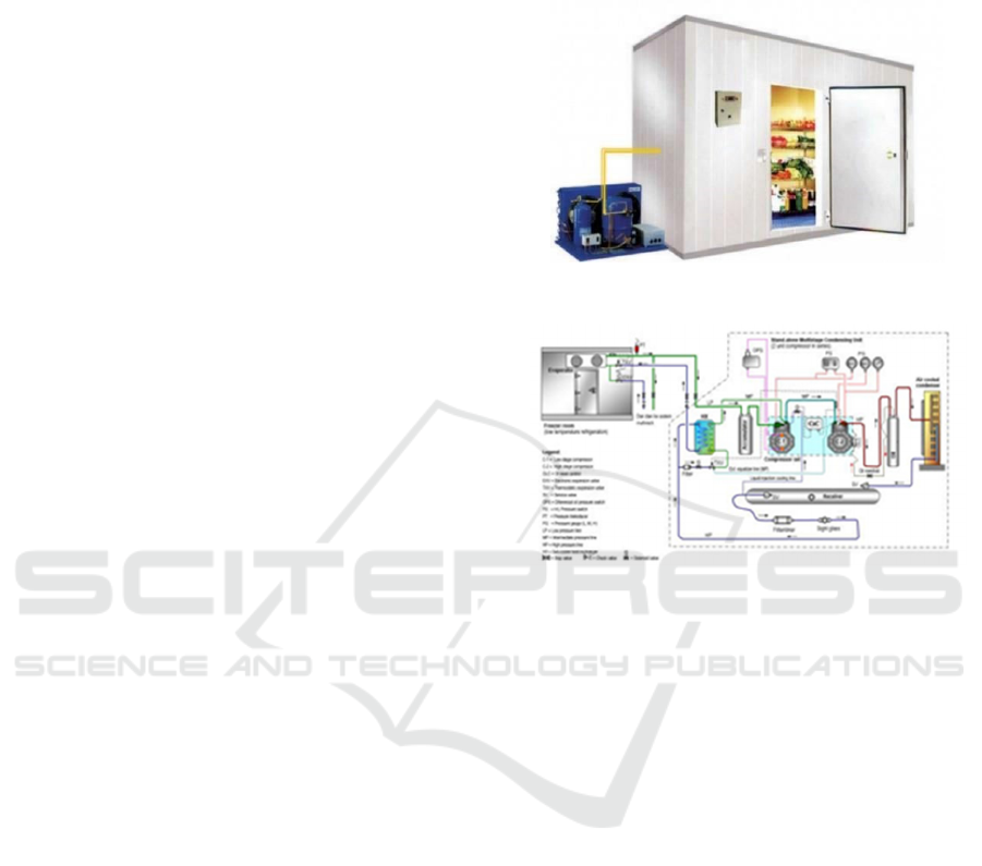
Figure 1: A Cold Storage.
Figure 2: A Multi-stage Cold Storage Piping.
The intercooler is usually placed at an
intermediate pressure
or between high pressure and
low pressure as well as between the two compression
levels which will determine the
compression work
per kg of steam. For a system with
compression
levels or multistage, it will be able to save some
work.
Intercooling in a refrigeration system can be done a
water cooled heat exchanger or by using a
refrigerant. A water-cooled intercooler may suffice
for two-stage
compressed air, but for refrigerant
compression, the water is
usually not cold enough.
Another method is to use liquid
refrigerant from
the condenser to the intercooler. The gas released
from the low-level compressor passes through the
liquid in the intercooler. The refrigerant will leave
the
incooler in the form of saturated vapor. A 2-stage
compressor with an intercooler is often an ideal way
to service a single
low-temperature evaporator.
These systems require less power than a single
compressor and these power savings will
frequently
cost extra equipment.
iCAST-ES 2021 - International Conference on Applied Science and Technology on Engineering Science
504
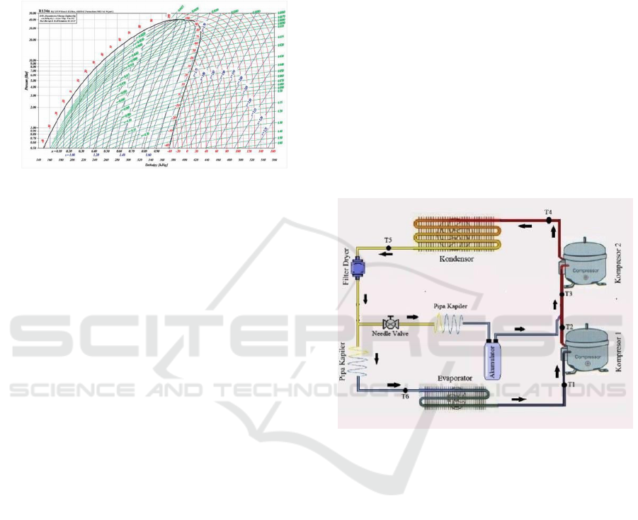
2.3 P - h Diagram
A P – h diagram is a diagram showing the
characteristics of the refrigerant gas. The x-axis
represents the enthalpy (h) and the y-axis shows the
pressure (P) as shown by the following figure
Figure 3: A P – h Diagram.
a.
Saturated liquid line
It is a curved line from the bottom left to the
critical point. It is at this point that the refrigerant
begins to evaporate. To the left of the line is the
super-cooled liquid area. To the right of the line is
the mixed phase.
b.
Saturated vapor line
It is a curved line from the right to the critical
point. At this point the refrigerant is in the
saturated vapor phase. To the right of the line is
the area of superheated steam. To the left of the
line is the mixed area.
c.
Pressure (P, in Bar)
Pressure is expressed by the ordinate axis (x). It is
a line of constant pressure (isobar), expressed in
psia ( pound per second absolute ) or bar.
d.
Entalphy (h, in KJ/ kg)
It is a vertical line on the Y axis, and is
isoenthalpy. It is the heat energy possessed by a
substance at a certain temperature.
e.
Temperature (T, in °C)
In the liquid area, the temperature line is
constant
(isothermal). Inside the dome the temperature
line is parallel to the pressure line (isobar) and in
the area
of superheated steam, the temperature
rises do not curve
towards the lower right
f.
Specific Volume (v in m³/ kg)
The constant specific volume line (isovolumery)
connects
the state points with the specific volume
with a slightly curved top right oblique direction.
g.
Entropy (s, in KJ/kg)
It is the property of measuring the degree of
disorder or irregularity at the microscopic level
(one unit of weight). The line of constant entropy
(insentropic) connects points of the same state. It
is a right slash from the bottom.
h.
Degree of Dryness (x)
The iso-degree dryness line shows the degree of
dryness of the wet vapor. It is the dividing line
of the flat lines between the saturated liquid line
and the saturated vapor line.
3 EXPERIMENT SETUP AND
PROCEDURE
3.1 Type of Research
The type of research carried out is the analysis of inter
cooler on multi-stage type cold storage which
includes numerical and experimental studies.
Figure 4: The design of multi-stage cold storage
refrigeration simulation.
3.2 Data Source
In this study, the data were obtained by conducting
direct testing on cold storage simulations with a
multistage system with and without an intercooler.
The data can be retrieved after the system works
normally. The data were immediately collected and
carried out 10 times with a time difference of 5
minutes.
3.3 Research Resources
The testing equipment used in this study is a cold
storage simulation with a multistage system designed
at the Refrigeration Laboratory, Mechanical
Engineering, Bali State Polytechnic with the
following specifications:
Experimental Study on the Effect of Intercooler on a Compressor Performance on Multistage Type Cold-storage Simulation
505
a.
A Piston Compressor, 1/10 PK
b.
A Condenser with fan cooling
c.
An evaporator
d.
A Capillary pipe
e.
A Refrigerant R 134a
3.4 Research Instrument
To assist the research, it is essential to provide the
supporting research instrument. The instruments are
described as follows.
a. Clamp Meter
It is a measuring instrument used to measure
electric current in a conductor cable energized
by electric current using its two clamping jaws
without having to have direct contact with the
electrical terminals. In general, Clamp Meter
has two functions: as an amperemeter and a
multimeter. Thus in addition to having two
clamping jaws, the Clamp Meter also has two
probes that can be used to measure Resistance,
AC Voltage, DC Voltage and there are even
certain models that can measure Frequency, DC
Electric Current, Capacitance and Temperature
b. Manifold Gauge
The manifold gauge has very large functions
such as refrigerant filling, pressure monitoring,
and repairing which involves the cooling
medium, namely the refrigerant in the
refrigeration system. The manifold is designed
with a standard construction so that it is easy to
understand. There are two gauges for checking
the suction side and the discharge side. The low
pressure gauge has a scale - 1 bar to 8.2 bar,
meanwhile the high pressure gauge has a scale
of 0 bar s / d 34 bar.
c. Thermocouple
A thermocouple is used to detect or calculate
temperature through two different types of metal
conductors which are joined at the ends to cause
a thermo-electric effect.
d. Stop watch
A stop watch is used to set the duration when
testing the system.
3.5 Research Procedure
The data collection process in a multistage cold
storage simulation system is carried out by following
the following test procedures.
a.
Preparation Steps
1. Preparing the measuring instruments that will
be used to collect data and check high pressure
components in the system.
2. Installing the thermocouple.
3. Installing the manifold gauge.
4. Ensuring that the measuring tools are
properly installed.
5. Ensuring that all tools attached to the system
function properly.
b.
Data Collection Steps
The processes of cold storage simulation testing
with a multistage system are carried out as
follows.
1. Turn the multistage cold storage simulation
engine on and make sure the system runs
normally. Let it runs for ± 30 minutes
2. After the system is running normally, record
the
results of data collection on the high
pressure, medium pressure, and low pressure
sides
3. Perform data collection at the intervals of five
minutes, and the recording is done for twelve
times.
4. After completing data collection, turn off the
system
5. The test results are then recorded in a table
4 RESULTS AND DISCUSSION
The data oftained from the multi stage type cold
storage simulator covering the temperature, pressure,
current, and voltage are presented in Table 1 and
Table 2.
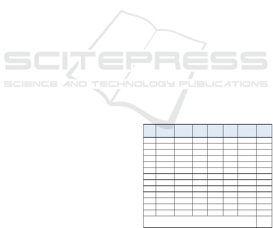
Table 1: Measurement Result Data on Multistage Cool
Storage System with Intercooler.
No T1
(
o
C)
T2
(
o
C)
T3
(
o
C)
T4
(
o
C)
T5
(
o
C)
T6
(
o
C)
LP
(Psi)
1 -6 45 19 55 30 -9 10
2 -7 48 19 56 31 -11 10
3 -10 48 19 59 31 -14 9
4 -10 49 18 69 31 -14 9
5 -10 49 18 69 32 -15 8
6 -10 49 18 70 32 -16 7
7 -12 50 18 70 32 -17 6
8 -14 50 18 70 32 -19 6
9 -16 50 18 72 32 -19 5
10 -16 51 18 72 33 -19 5
11 -17 53 18 75 33 -19 5
12 -17 55 18 75 33 -19 5
R -12 49,7 18,2 67 31,8 -15,5 7,08
1,56
(Bar)
iCAST-ES 2021 - International Conference on Applied Science and Technology on Engineering Science
506
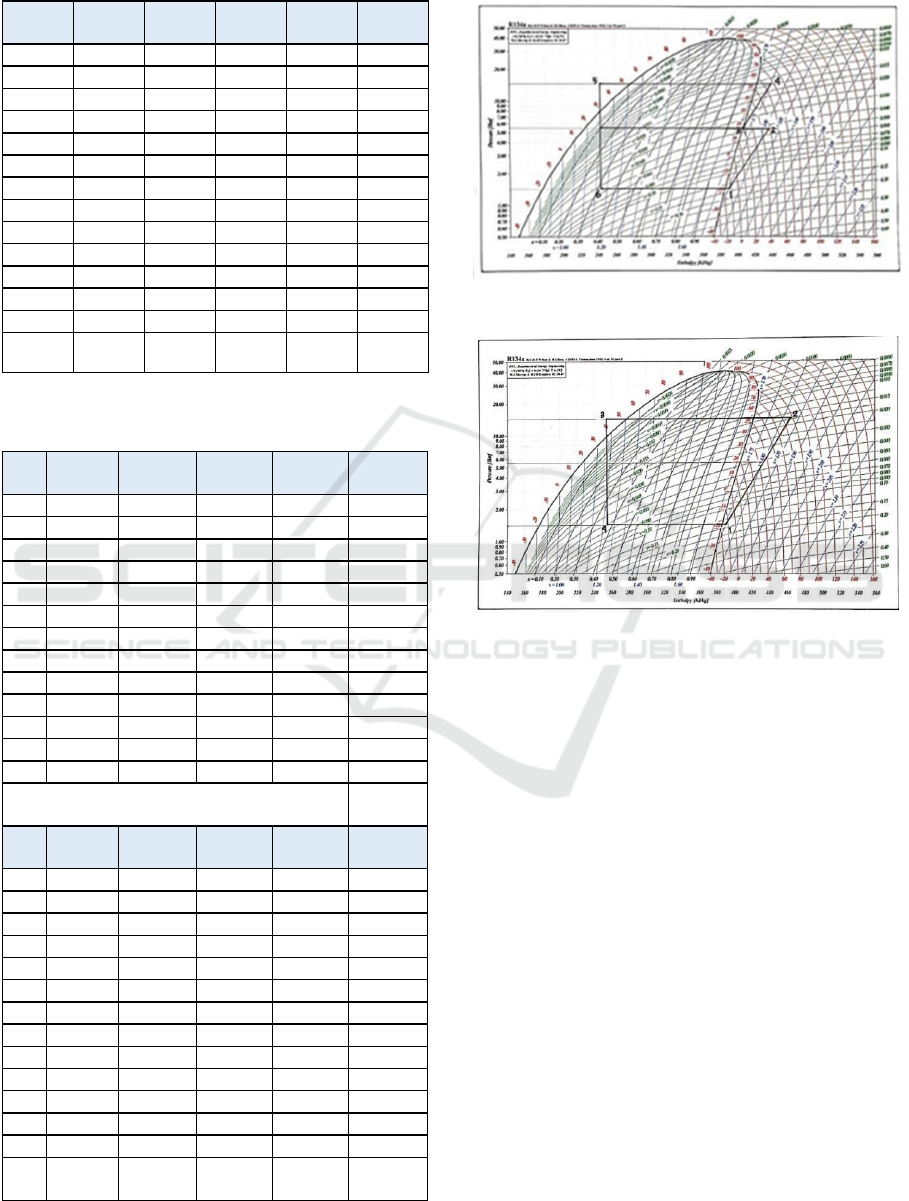
Table 1: Measurement Result Data on Multistage Cool
Storage System with Intercooler (cont.).
No MP
(Psi)
HP
(Psi)
A1
(Amp)
A2
(Amp)
V
(Volt)
1 60 200 0,81 0,91 220
2 68 200 0,82 0,90 220
3 60 210 0,82 0,90 220
4 62 210 0,82 0,90 220
5 65 210 0,82 0,90 220
6 65 215 0,82 0,90 220
7 65 215 0,82 0,90 220
8 65 215 0,82 0,90 220
9 68 220 0,82 0,90 220
10 68 220 0,82 0,90 220
11 68 220 0,82 0,90 220
12 68 220 0,82 0,90 220
R 64,7 211 0,81 0,90 220
5,46
(Bar)
15,7
(Bar)
Table 2: Measurement Result Data on Multistage Cool
Storage System without Intercooler.
No T1
(
o
C)
T2
(
o
C)
T3
(
o
C)
T4
(
o
C)
LP
(Psi)
1 -6 85 37 -11 10
2 -7 86 38 -14 10
3 -9 87 38 -14 9
4 -10 88 38 -15 9
5 -11 88 39 -16 8
6 -12 90 39 -17 7
7 -14 90 39 -19 6
8 -14 91 39 -19 6
9 -16 92 39 -19 5
10 -18 92 40 -20 5
11 -18 93 40 -20 5
12 -18 93 40 -20 5
R -12,7 89,5 39 -17 7,08
1,50
(Bar)
No MP
(Psi)
HP
(Psi)
A1
(Am
p
)
A2
(Am
p
)
V
(Volt)
1 60 200 0,81 0,91 220
2 68 200 0,82 0,90 220
3 60 210 0,82 0,90 220
4 62 210 0,82 0,90 220
5 65 210 0,82 0,90 220
6 65 215 0,82 0,90 220
7 65 215 0,82 0,90 220
8 65 215 0,82 0,90 220
9 68 220 0,82 0,90 220
10 68 220 0,82 0,90 220
11 68 220 0,82 0,90 220
12 68 220 0,82 0,90 220
R 64,7 211 0,81 0,90 220
5,46
(Bar)
15,7
(Bar)
Based on table 1 and 2 a P-h diagram can be drawn as
follows.
Figure 5: P-h Diagram system with intercooler.
Figure 6: P-h Diagram system without intercooler
Based on the figure, the effect of refrigeration and
compressor work from the system with an intercooler
can be
calculated as follows:
a.
Refrigeratiom
Effect (RE) RE
= h1 - h6 (kJ/kg)
= 390 – 242(kJ/kg)
= 148kJ/kg
Where:
RE = Refrigeration Effect
h1 = The enthalpy of refrigerant leaving the
evaporator
(kJ/kg)
h6 = The enthalpy of refrigerant entering the
evaporator
(kJ/kg)
Thus the refrigeration effect of a
multistage cold
storage system with an
intercooler is 148 Kj/Kg.
b.
Compression Work (Cw)
Cw = (h4 – h3) + (h2 – h1) (kJ/kg)
= (441 – 408) + (438 – 390) (kJ/kg)
= 33 + 48 (kJ/kg)
= 81kJ/kg
Experimental Study on the Effect of Intercooler on a Compressor Performance on Multistage Type Cold-storage Simulation
507

Where:
Cw = Compression work
h4 = enthalpy of refrigerant vapor leaving
compressor 2 (kJ/kg)
h3 = enthalpy of refrigerant vapor entering
compressor 2 (kJ/kg)
h2 = enthalpy of refrigerant vapor leaving
compressor 1 (kJ/kg)
h1 = enthalpy of refrigerant vapor entering
compressor 1 (kJ/kg)
Therefore the compression work of a multistage cold
storage system with an intercooler is 81 Kj/Kg.
From the obtained results of the refrigeration effect
and compression work, it can be applied into the
following COP formula:
COP =
𝑅𝐸
𝐶𝑤
=
148
81
= 1,83
Where:
COP = Coeffision of Performance
RE =
Refrigeration
Effect
Cw =
Compression
work
Therefore the theoretical COP obtained
from a system
with an intercooler is 1.83.
For a multistage cool-storage system
without an intercooler, the following results are
obtained.
a. Refrigeration Effect (RE)
RE = h2 –
h1 (kJ/kg)
= 390 – 255(kJ/kg)
= 135kJ/kg
Where:
RE
= Refrigeration Effect
h1 = The enthalpy of refrigerant leaving the
evaporator
(kJ/kg)
h2
=
The enthalpy of refrigerant
vapor
leaving
compressor 1 (kJ/kg)
So the refrigeration effect from cold storage without
an intercooler is 135 Kj/Kg.
b. Compression
work (Wc) Wc =
(h1 – h4) (kJ/kg)
= (465 – 390)(kJ/kg)
= 75(kJ/kg)
Where:
W
= Work compression
h4
=
The enthalpy of refrigerant
vapor
leaving
compressor 2 (kJ/kg)
h1
=
The enthalpy of refrigerant vapor
entering
compressor 1 (kJ/kg)
So the compression work of a cold storage without
an intercooler is 75 Kj/Kg.
From the obtained results of the refrigeration
effect and compression work, it can be applied into
the following COP formula:
COP =
𝑅𝐸
𝐶𝑤
=
135
75
= 1,80
Where:
COP = Coeffision of Performance
RE = Refrigeration Effect
Cw = Compression work
Therefore the theoretical COP obtained from a system
without an intercooler is 1.80. The maximum
temperature of the system can also be directly seen on
the pH diagram and the energy consumption will be
obtained from the enthalpy difference in the system’s
compression work.
5 CONCLUSION
Based on the research results obtained a cool-storage
system with intercooler has a COP of 1.83 and the
maximum
temperature of the system is 67
o
C. Without
an intercooler, its COP is 1.80 and the maximum
temperature of the system is
89.5
o
C. Thus the
system’s performance by using an intercooler is better
than without an intercooler.
ACKNOWLEDGMENT
Thank you to the Bali State Polytechnic for the
financial
assistance that has been given so that this
research can be
carried out.
REFERENCES
Asep Supriatna. 2019. Keuntungan dan Kerugugian
Kompresor
Torak. tptusmkn1cimahi.blogspot.com/
2010/01/kompresor.html. Retrieved on January 25
th
2020.
iCAST-ES 2021 - International Conference on Applied Science and Technology on Engineering Science
508

Calm,J.M. 2012 Options and Outloc for Chiler Frefrigernts.
International Jurnal Of Refrigeration.
Chaiwongsa, Praitoon., Wongwises, Somchai. 2007,
“Experimental study on R-134a refrigeration system
using a two-phase ejector as an expansion device”.
International Journal of Refrigeration.
Febri Amandani. 2018. Kompresor
ReciprocatingMultistage. https://id.scribd.com/doc/
179610930/Kompresor-Multi- Stage. Retrieved on
January 25th 2020.
Indartono 2015. Perkembangan Terkini Teknologi
Refrigerasi URL:http://www.beritaiptek.com
Jahar Sakar. 2010. Layout and P-H Diagram Of Two-Stage
CO 2 System. https://www.researchgate.net/
figure/Layout-and-p-h-diagram-of-two-stage-CO-2-
system- with_fig3_215549766. Retrieved on January
2nd 2020.
Michael F. Taras, Alexander Lifson 2020. Refrigeran
System with Intercooler And Liquid.Vapor Injection.
Retrieved on March 25th 2021.
Pravind D. Dhakane,M.S.Joshi, 2020. Design Of Two
Stage Vapor Compression Refigeration System With
Water Intercooler Retrieved on March 25th 2021.
Sam. 2009. Multistage Refrigeration Systems.
http://www.refrigeratordiagrams.com/refrigeration-
systems-and-applications/refrigeration-cycles-and-
systems/multistage-refrigeration-systems.html.
Retrieved on January 23rd 2021.
Stoecker F Wilbert, Jones W J, Supratman Hara. 1994.
Refrigerasi dan Pengkondisian Udara
Yohanes Johan. 2017. BAB II DASAR TEORI. 2.1 Cold
Storage. https://docplayer.info/42116751-Bab-ii-
dasar- teori-2-1-cold-storage.html. Retrieved on
January 12th 2021.
Experimental Study on the Effect of Intercooler on a Compressor Performance on Multistage Type Cold-storage Simulation
509
