
Thermal Performance of Hot Water System Produced by Air
Conditioning Coupled with Heat Recovery
Putu Wijaya Sunu
1a
, I Made Suarta
1b
, Daud Simon Anakottapary
1c
,
C. Bambang Dwi Kuncoro
2d
, I Dewa Gede Agus Triputra
1e
, I Dewa Made Cipta Santosa
1f
,
I Made Ari Dwi Suta Atmaja
3
, Ketut Suarsana
4
and I Wayan Edi Arsawan
5g
1
Mechanical Engineering Department, Bali State Polytechnic, Badung, Bali, Indonesia
2
Refrigeration, Air Conditioning and Energy Engineering Department, National Chin-Yi University and Technology,
Taiwan
3
Electrical Engineering Department, Bali State Polytechnic, Badung, Bali, Indonesia
4
Mechanical Engineering Department, Udayana University, Badung, Bali, Indonesia
5
Business Administration Department, Bali State Polytechnic, Badung, Bali, Indonesia
idmcsantosa@pnb.ac.id, arisuta@pnb.ac.id, wayanediarsawan @pnb.ac.id, bkuncoro@ncut.edu.tw, suarsana@unud.ac.id
Keywords: Air Conditioning, Heat Recovery, Free Hot Water, Twisted Tapes.
Abstract: Shifting the air conditioning (AC) cycle from conventional to efficiently novel cycle is one of the effective
ways to save energy and reach sustainability. In this experimental investigation, an effort had been made in
design, fabrication, and evaluated the thermal performance of air conditioning coupled with heat recovery to
produce free hot water for residential. It is also investigated the effect of the number of twisted tapes insert
inside the heat recovery unit. The experiment was conducted in a 4 x 4 m room with 1 pk compressor power.
Heat recovery was used to increase water temperature after coming in contact with hot refrigerant from the
discharge of the compressor. This hot water was delivered to the thermal storage tank. The result indicated an
increase in temperature and energy of the heat recovery tank by around 0.2%, 6.0%, 6.8%, 17.3% using one,
two, three, four twisted tapes.
1 INTRODUCTION
The efficient and conservation energy system for
optimization in refrigeration, heating, ventilating, and
air conditioning (RHVAC) in building energy
involves the employment of a heat exchanger as a
thermal recovery unit (Sunu et al., 2020b; 2017a,
2017b). Heat exchanger exchanging the heat of the
hot to the cold side and vice versa of the conditioned
part/space. From its function in general point of view,
the heat exchanger has an important role. Various
types of heat exchangers are applied in the RHVAC
field. (Sunu et al., 2020c, 2017c, 2017d) this research
a
https://orcid.org/0000-0002-6915-0475
b
https://orcid.org/0000-0001-5715-7170
c
https://orcid.org/0000-0001-7856-6512
d
https://orcid.org/0000-0002-5054-2794
e
https://orcid.org/0000-0002-5054-7876
f
https://orcid.org/0000-0002-9912-629X
g
https://orcid.org/0000-0001-8493-5249
applied a double pipe heat exchanger which scratched
with grooves to optimize heat transfer and pressure
losses. It was found that the addition of longitudinal
and circumferential grooves on the walls of the heat
exchanger gave positive results on heat transfer and
pressure losses. Research on the other types of heat
exchangers such as plate heat exchanger (Nur et al.,
2015). The result shows the increases of plate spacing
give effect to the increase of total area on the other
hand the rises of plate spacing decrease the fluid
pressure drop. Optimization of the heat exchanger
shape is done to improve the heat transfer process and
hydraulic characteristics in the heat exchanger. (Ji et
434
Wijaya Sunu, P., Made Suarta, I., Simon Anakottapary, D., Bambang Dwi Kuncoro, C., Dewa Gede Agus Triputra, I., Dewa Made Cipta Santosa, I., Made Ari Dwi Suta Atmaja, I., Suarsana,
K. and Wayan Edi Arsawan, I.
Thermal Performance of Hot Water System Produced by Air Conditioning Coupled with Heat Recovery.
DOI: 10.5220/0010947100003260
In Proceedings of the 4th International Conference on Applied Science and Technology on Engineering Science (iCAST-ES 2021), pages 434-439
ISBN: 978-989-758-615-6; ISSN: 2975-8246
Copyright
c
2023 by SCITEPRESS – Science and Technology Publications, Lda. Under CC license (CC BY-NC-ND 4.0)

al., 2015) study a complete investigation on heat
transfer enhancement techniques special for flow in
the pipe. The main purposes of the techniques are to
generate vortex inside the flow so as to generate the
fluid mixing and advection. The utilization of vortex
generators increases the possibility to improve
transport phenomena.
To generate the swirl and increase the turbulence
flow can be done in several ways, which can be
separated into two major ways: one is active methods
and the other is passive methods. In the first method
the flow activated driven by the force convection
using machinery driving the fluid changing its flow
direction, another active way is using vibration.
Especially in the second method or passive ways,
surface variation has been established for increasing
the transport of energy and pressure drop in a
turbulent flow. This modification method applying
surface techniques that induced the formation of the
vortex at the secondary flow (Lorenz et al., 1995;
Adachi et al., 2001, 2009; Eiamsa-ard et al., 2008,
2009; Jain et al., 2013; Wang et al. 2013;
Piriyarungrod et al., 2018; Pan et al., 2020). The heat
transport mechanism in heat exchanger equipped with
passive technique can actually be developed for
producing turbulence in the fluid flow.
The thermal performance of a heat exchanger for
heat recovery application can be enhanced by various
heat transfer enhancement techniques either active or
passive technique. One of the applications in the
industrial is by applying the system of heat recovery
using a heat pipe heat exchanger (HPHE) (Remeli et
al., 2015). Modification via surface scraped apply in
heat exchanger have been conducted for the fluid with
high viscosity pharmaceutical, food, and chemical
industries (Dehkordi et al., 2015). Nowadays, high
energy-efficient buildings, the deficit of world
energy, and carbon footprint and emission have
strong demand on the residential energy efficiencies
(Yang et al., 2014). To make the advantages of
mechanical air conditioning for residential, air
conditioning coupled with heat recovery was
introduced. Heat recovery application in air
conditioning systems has become more popular in
these recent years as an economical-effective method.
It reuses the waste thermal energy in refrigerant
flowing through the condenser and thereby produce
free hot water (Sunu et al., 2020a). This system needs
an additional heat exchanger which exchanges the
heat of refrigerant-to-water and places between
compressor and condenser for heat recovery (Jie et
al., 2015). This installation mechanism can assist
combined space conditioning and free water heating
and is very suitable in tropical regions like Indonesia.
There has been a fast movement of use and
optimization of the waste heat recovery unit
integrated with air conditioning since the last few
decades (Lee et al., 1996). (Ji et al., 2003) propose the
use of a tank of thermal storage as energy storage to
enhanced heat recovery room air-conditioner.
(Monerasinghe et al., 1982) conducted a study and
feasibility of heat recovery integrated with room air-
conditioning. The use of storage-enhanced heat
recovery from room air-conditioner to produce free
hot water and offer a space air conditioning system
for energy conservation. On the other hand, the
additional heat recovery process makes the
fluctuations of pressure (Jie et al., 2015). The result
shows the overall COP of TEV found 12.5–20.9%
higher than the capillary tube.
According to relevant research works above are
none, to identify all of the passive technique for heat
transfer is chosen for use as optimized heat that is
applicated in residential building. A twist tape is quite
a promising passive technique. A prototype of a heat
recovery unit equipped with the twist tape devices
was arranged for experimental investigation. In the
prototype, the twisted tape could be activating the
turbulence flow and increase the advection inside the
heat recovery. In this experiment, the operational
working parameters on the heat recovery unit were
monitored. Based on the experimental marks, the
performances of the four-case twisted heat recovery
systems and a system without heat recovery were
determined and compared.
2 EXPERIMENTAL METHODS
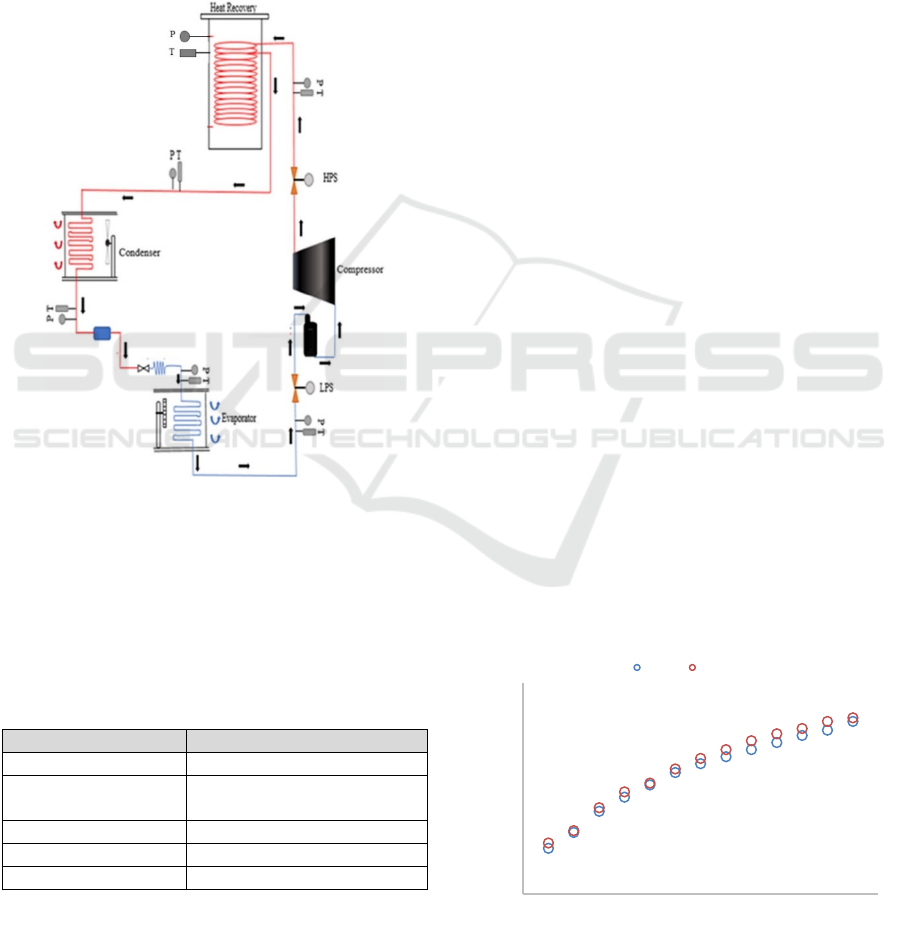
Prototype of heat recovery unit equipped with twist
tape was built in the laboratory, as a sketch in Fig. 1.
The experimental test rig comprises an outdoor and
an indoor unit, a shell and coil HX, and a water
centrifugal pump. The nominal evaporator cooling
capacity of 9000 Btu/h and the power compressor
consumption of 0.75 kW. Refrigerant 22 (R22) is
used as a working fluid. A DX evaporator as an indoor
unit comprises a copper tube and aluminium fins.
Meanwhile, the outdoor unit includes a capillary tube,
a tube-and-fin air-cooled condenser, and a hermetic
rotary compressor.
This research aims to reveal the performance of
the heat recovery unit equipped with a number twist
tape. The heat recovery unit is installed in the
discharge line of the compressor i.e., between the
compressor and condenser. In heat recovery, the heat
exchange occurs between refrigerant and water at a
specified temperature without direct contacting. The
Thermal Performance of Hot Water System Produced by Air Conditioning Coupled with Heat Recovery
435
specifications of the indoor unit, outdoor unit, heat
recovery unit, and the centrifugal pump are presented
in Table 1. The temperature controlling for cooling
the room conditioned is only on-off control
accordance to temperature set point on the thermostat.
There is a gate valve to adjust the refrigerant flow
whether using heat recovery or not. This mechanism
provided a by-pass loop for refrigerant flow. To
control the level of water inside the heat recovery
unit, an electrical DC controlling mechanism was
proposed.
Figure 1: Experimental setup.
The point of comparison in this experiment is the
present of a number of twist tape inside the heat
recovery. The water pumped by a 125 W centrifugal
pump from the storage tank to heat recovery and
flowing back to the storage tank. The main
component for refrigeration was listed below,
Table 1: Specification of main component.
Component Specification
Compressor unit Hermetic, Rotary 750 W, R22
Condenser unit Fin and tube with air cooled
system.
Expansion device unit Capillary tube
Evaporator unit Fin and tube exchanger
Heat recovery unit Shell and coil exchanger
According to this investigation, as shown in Fig.1, the
flow of recovery heat can be divided into two
portions: first capturing waste heat by heat transfer
process between refrigerant and water inside heat
recovery, and the second storing the absorbed heat in
the thermal storage tank. Four different numbers of
twist tape used are one twist, two twists, three twists,
and four twists. It is important to have sufficient
information and analysis of the effect of the presence
of twist tape inside the heat recovery to the absorbing
waste heat. These variables will correlate to the
performance of the heat recovery system.
The circulating water to heat recovery from the
thermal storage tank was maintained at 12 liters per
minute. The water absorbed heat in heat recovery.
The temperature of circulating water increased by the
contacted process with refrigerant tube and then
entered the storage tank through the connection
pipeline. In the storage tank, the water releasing the
heat to the storage water by heat exchanged process.
The circulating water is sucked by the pump for
flowing back to the heat recovery. In this experiment,
the operating parameters on the overall systems were
recorded using instrumentation equipment.
Thermocouples (K type) with frequency 1 Hz for
3600 s measured the refrigerant temperatures. The
water flow rate was measured by a rotameter and
maintain at 12 lpm.
3 RESULT AND DISCUSSION
The result and discussion section deliberate the
performance of the operated heat recovery (HR)
without twist tape compared to heat recovery with a
number of twist tape under the same water volume
rate condition. The performance is determined on the
operation constraints on the water heating
temperature inside heat recovery and the energy
absorbed by the heat recovery system. Temperature
comparisons of with and without twist tape of the
systems are presented below.
Figure 2: The time series temperature of one twist tape.
30
32
34
36
38
40
42
0 2 4 6 8 10 12 14
Temperature ( oC)
Time (x 300s)
1 Twist No Twist
iCAST-ES 2021 - International Conference on Applied Science and Technology on Engineering Science
436
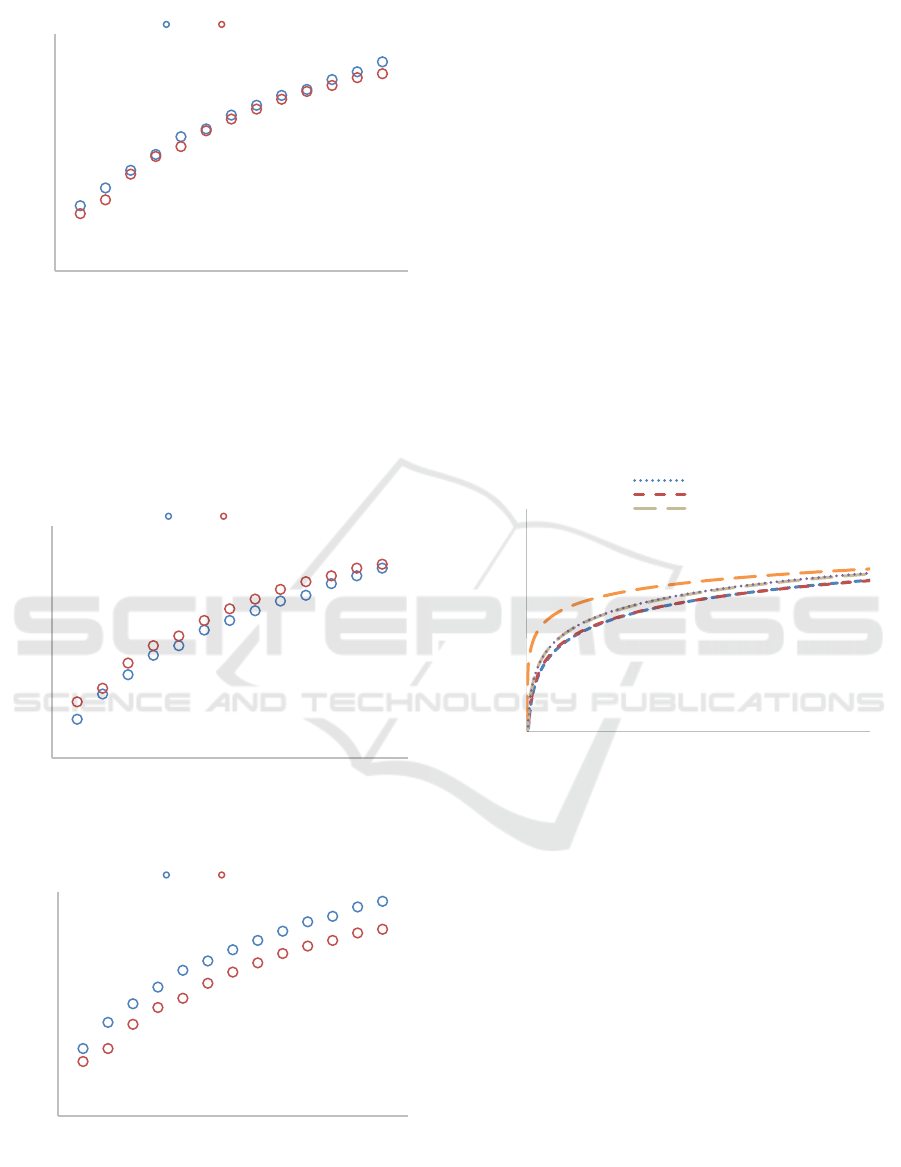
Figure 3: The time series temperature of two twist tape.
Fig. 2 to 5 compares the temperature of heat recovery
for the systems with/without twist tape. The
temperature of HR without twist tape was taken as the
temperature reference to calculate the performance of
the heat recovery system with the twisted tape.
Figure 4: The time series temperature of three twist tape.
Figure 5: The time series temperature of four twist tape.
For the heat recovery system without twist tape, the
fluid flow inside HR flowing from the bottom region
to the upper region without disturbance. The fluid
flow in smooth line and relatively constant velocity to
the discharge section. Meanwhile, in the heat
recovery with twist tape, the fluid flow from the
bottom region to the upper region starting disturbance
with the presence of twist tape. The twisted tape
induced the flow condition inside the heat recovery
unit. They increase the turbulence strength,
recirculation region, and fluid momentum. These
phenomena will tear the thermal boundary layer
outside the copper coil tube so that the thermal
obstacle will be thinner. The disturbance caused by
the presence of twist tape will increase as increase the
number of twist tape. In this investigation for four
number of twist-tape has the highest heat recovery
temperature. This phenomenon proves that the
highest number of twist tape has the highest
randomness of fluid flow.
Figure 6: The time series of energy absorbed by heat
recovery.
The presence of twist tape the heat recovery will give
additional flow disturbance inside it. The temperature
of the fluid inside heat recovery will increase and has
considered an increase the efficiency. The energy
absorbed shows in Fig.6 and follow the equation
below,
𝑄 𝑚 .𝐶𝑝.𝑑𝑡 eq.1
where Q is the heat absorbed by fluid inside the heat
recovery (kW); 𝑚 is the mass flow rate (kg/s); Cp is
the heat capacity at constant pressure (kJ/kg. K); dt is
temperature different of fluid (
o
C).
Fig. 6 compares the energy of each case in this
investigation for interval 3600 s. It is described that
the heat recovery equipped with four twist tape has
the highest energy absorbed from the refrigerant tube.
The explanation why the energy absorbed by twist-
30
32
34
36
38
40
42
0 2 4 6 8 10 12 14
Temperature ( oC)
Time (x 300s)
2 Twist No Twist
30
32
34
36
38
40
42
0 2 4 6 8 10 12 14
Temperature ( oC)
Time (x 300s)
3 Twist No twist
30
32
34
36
38
40
42
02468101214
Temperature ( oC)
Time (x 300s)
4 Twist No Twist
0,0
0,2
0,4
0,6
0,8
1,0
0 400 800 1200 1600 2000 2400 2800 3200 3600
Energy (kW)
Time (s)
Logarítmica (No twist tape)
Logarítmica (1 tt)
Logarítmica (2 tt)
Thermal Performance of Hot Water System Produced by Air Conditioning Coupled with Heat Recovery
437

taped heat recovery is the same way with the
temperature phenomena.
4 CONCLUSIONS
The objective of this research is to increase the waste
heat absorbed by the heat recovery using additional
twist tape. An experimental setup has been developed
to validate the effect of number of twist tape on the
heat absorbed parameter. It can be concluded from the
results of this study that:
1. It is possible to apply the proposed system to
increasing the temperature of heat recovery.
2. Based on concern operating condition the
average heat absorbed 0.56, 0.59, 0.59, 0.65
kW for modified heat recovery.
ACKNOWLEDGEMENTS
The authors would like to express sincere gratitude to
DRPM, Kemdikbud-Ristek, Republic of Indonesia
for research fund with No. 249/E4.1/AK.04.PT/2021.
Also Politeknik Negeri Bali with research project
number is No. 42/PG/PL8/2021.
REFERENCES
Adachi T. and Uehara H., 2001. Correlation between heat
transfer and pressure drop in channels with
periodically grooved parts. In Int. J. Heat Mass
Transfer.
Adachi T., Tashiro Y., Arima H., Ikegami Y., 2009.
Pressure drop characteristics of flow in a symmetric
channel with periodically expanded grooves. In Chem.
Eng. Sci.
Dehkordi K. S, Fazilati M. A, Hajatzadeh A. 2015. Surface
Scraped Heat Exchanger for cooling Newtonian fluids
and enhancing its heat transfer characteristics, a
review and a numerical approach. In Applied Thermal
Engineering.
Eiamsa-ard S. and Promvonge P., 2008. Numerical study on
heat transfer of turbulent channel flow over periodic
grooves. Int. Commun. In Heat Mass Transfer.
Eiamsa-ard S. and Promvonge P., 2009. Thermal
characteristics of turbulent rib-grooved channel flows.
In Int. Commun. Heat Mass Transfer.
Jain M., Rao A., Nandakumar K., 2013. Numerical study on
shape optimization of groove micromixers. In
Microfluid Nanofluid.
Jie J., and Lee W.L., 2015. Experimental study of the
application of intermittently operated SEHRAC
(storage-enhanced heat recovery room air-conditioner)
in residential buildings in Hong Kong. In Energy.
Ji J., Chow T. T., Pei G., Dong J., and He W., 2003.
Domestic air conditioner and integrated water heater
for subtropical climate. In Applied Thermal
Engineering.
Ji W-T, Jacobi A.M., He Y-L, Tao W-Q., 2015. Summary
and evaluation on single-phase heat transfer
enhancement techniques of liquid laminar and
turbulent pipe flow. In Int J Heat Mass Transfer.
Lee A. H. W., and Jones J. W., 1996. Thermal performance
of a residential desuperheater/water heater system. In
Energy Conversion and Management.
Lorenz S., Mukomilow D., Leiner W., 1995. Distribution
of the heat transfer coefficient in a channel with
periodic transverse grooves. In Exp. Therm. Fluid Sci.
Monerasinghe N. J., Ratnalingam R., and Lee B. S., 1982.
Conserved energy from room air-conditioners for
water heating. In Energy Conversion and Management.
Nur Rohmah, Ghalya P., Andri J. P, Rakhmad I. P., 2015.
The effect of plate spacing in plate heat exchanger
design as a condenser in organic Rankine cycle for low
temperature heat source. In Energy Procedia.
Pan J., Bian Y., Liu Y., et al., 2020. Characteristics of flow
behavior and heat transfer in the grooved channel for
pulsatile flow with a reverse flow
. In International
Journal of Heat and Mass Transfer.
Piriyarungrod N., Kumar M., Thianpong C., et al., 2018.
Intensification of thermo-hydraulic performance in heat
exchanger tube inserted with multiple twisted-tapes. In
Applied Thermal Engineering.
Remeli F., Verojporn K., Singh B., Kiatbodin L., Date A.,
Akbarzadeh A., 2015. Passive Heat Recovery System
using Combination of Heat Pipe and Thermoelectric
Generator. In Energy Procedia.
Sunu P.W., Anakottapary D. S., Suirya I W., Puspa Indra I
B., Rahtika I P. G. S., Putra D. M. R. S., Yusa I G. S.
G., Wijayantara I M., 2020a. A brief comparative
thermodynamics review of domestic air conditioning
system with or without installed heat recovery. In J.
Phys.: Conf. Ser.
Sunu P.W., Anakottapary D. S., Susila I D. M., Santosa I
D. M. C., Indrayana I N. E., 2020b. Study of thermal
effectiveness in shell and helically coiled tube heat
exchanger with addition nanoparticles. In J. Phys.:
Conf. Ser.
Sunu P. W, Anakottapary D. S, Suarta I M., Santosa I D. M.
C, Suarsana K., 2020c. Heat transfer enhancement and
friction in double Pipe heat exchanger with various
number of longitudinal grooves. In Acta Polytechnica.
Sunu P. W., Anakottapary D.S., Mulawarman A.A.N.B.,
Cipta Santosa I D. M., Negara I P.S., 2017a. Heat
Transfer Characteristics of Fan Coil Unit (FCU) Under
the Effect of Chilled Water Volume Flowrate. In Journal
of Physics: Conf. Series 953 (2017a) 012058.
Sunu P.W, Rasta I M., Anakottapary D.S., Suarta I M.,
Cipta Santosa I D. M, 2017b. Capillary Tube and
Thermostatic Expansion Valve Comparative Analysis
in Water Chiller Air Conditioning. In Journal of
Physics: Conf. Series.
Sunu P. W., Arsawan I M., Anakottapary D. S., Santosa I
D. M. C., Yasa I K. A., 2017c. Experimental Studies on
iCAST-ES 2021 - International Conference on Applied Science and Technology on Engineering Science
438

Grooved Double Pipe Heat Exchanger with Different
Groove Space. In Journal of Physics: Conf. Series.
Sunu P.W., and Rasta I M., 2017d. Heat Transfer
Enhancement and Pressure Drop of Grooved Annulus
of Double Pipe Heat Exchanger. In Acta Polytechnica.
Wang C., Liu Z.L., Zhang G.M., Zhang M., 2013.
Experimental investigations of flat plate heat pipes with
interlaced narrow grooves or channels as capillary
structure. In Exp. Therm. Fluid Sci.
Yang W, Fu-Yun Zhao, Jens K., Di Liu, Li-Qun Liu, Xiao-
Chuan Pan, 2014. Cooling energy efficiency and
classroom air environment of a school building
operated by the heat recovery air conditioning unit. In
Energy.
Thermal Performance of Hot Water System Produced by Air Conditioning Coupled with Heat Recovery
439
