
Analysis Damage Cylinder Head Engine on QSK 50 MCRS
Hamka Munir, Ismail Ramli and Misdar Alamsyah
Nunukan State Polytechnic, Heavy Vehichle Study Program, Jl. Ujang Dewa, Nunukan, Indonesia
Keywords: Cylinder Head, Engine, Damage, QSK 50 MCRS, Analysis.
Abstract: Damage that often occurs to the cylinder head is usually a lack of radiator air so that the engine may
overheat, then the cylinder head packing/gasket is damaged due to prolonged use or errors during
installation. This study aims to determine the problems that occur to the cylinder head, especially on the
QSK 50 MCRS engine, so that the treatment of the cylinder head is better, in order to optimize engine
operation in industrial processes. This research was conducted to obtain data in order to determine the cause
of the cylinder head damage on the QSK 50 MCRS engine. There are several steps will be done including
cleaning, visual inspection, and measurement and analysis of damage to the cylinder head. The results of
this study indicate that there is erosion during the component cleaning process. There is damage on each
surface of the combustion chamber at the cylinder head. The characteristics of the damage indicated that
there has been cavitation erosion on the surface of the combustion chamber. Cavitation erosion occurs on
the surface of the combustion chamber due to air bubbles that burst or explode during the power stroke of
the engine's four stroke cycle. Cavitation erosion is characterized by a surface with small holes. Analysis of
the 16 cylinder head QSK 50 MCRS shows that all cylinder heads can still be used, because the cylinder
heads are still within the standard coverage set out in the manual.
1 INTRODUCTION
Diesel engine is an internal combustion engine
(Internal Combustion Engine), whose fuel is sprayed
into the cylinder chamber when the piston is at top
dead center (TDC). This occurs because of the air in
the cylinder has a high heat, and could making it
easier for the fuel that has been injected to burn by
itself. Diesel engines generally have main
components such as pistons, valves, crankshafts,
high-pressure fuel pumps and other driving
mechanisms. The energy generated by the diesel
engine through the combustion of fuel that occurs in
the cylinder. This causes the displacement of the
piston movement in the cylinder which is carried out
by the crankshaft on the bearings through the
connecting rod.
Cylinder head is part of the cylinder block that
serves to close the cylinder cavity, and the space is
the combustion chamber. The cylinder head,
combustion in the cylinder chamber can occur. The
cylinder block is referred to as the base engine part
or a major component of the engine. The cylinder
head is called the second base because this
component forms the basis for several components
on the upper engine. The cylinder head will receive a
heavy load because it withstands compression
pressure, so that in it leads occur some damage to
this section.
Damage that can occur to the cylinder head
includes damaged cylinder head packing which
causes compression to leak and the engine does not
function properly. The damaging can occur to the
connection between 2 cylinders or to the oil and air
connection, which results in the engine not working
properly. Cylinder heads that experience cracks
usually occur in diesel engines, cracks that occur due
to overheating, where the engine overheats caused
by excessive load or the cooling system is damaged
or damaged, one of them. Cracks are also often
caused by malfunctioning of the thermosat where
when the temperature increases and the thermostat
does not open.
2
RESEARCH METHODOLOGY
We strongly encourage authors to use this document
for the preparation of the camera-ready. Please
follow the instructions closely in order to make the
Munir, H., Ramli, I. and Alamsyah, M.
Analysis Damage Cylinder Head Engine on QSK 50 MCRS.
DOI: 10.5220/0010946100003260
In Proceedings of the 4th International Conference on Applied Science and Technology on Engineering Science (iCAST-ES 2021), pages 373-378
ISBN: 978-989-758-615-6; ISSN: 2975-8246
Copyright
c
2023 by SCITEPRESS – Science and Technology Publications, Lda. Under CC license (CC BY-NC-ND 4.0)
373
volume look as uniform as possible (Moore and
Lopes, 1999). Please remember that all the papers
must be in English and without orthographic errors.
Do not add any text to the headers (do not set
running heads) and footers, not even page numbers,
because text will be added electronically.
For a best viewing experience the used font must
be Times New Roman, on a Macintosh use the font
named times, except on special occasions, such as
program code (Section 2.3.8).
2.1 QSK 50 MCRS Engine
Specification Data
The QSK is a Cummins engine model. The QSK50
is an engine with V-16 cylinder configuration with a
total volume (displacement) of 50 liters. The
Modular Common Rail Fuel System (MCRS) has a
simplified design that provides a constant high
injection pressure regardless of engine speed or load
conditions. The advantages of this engine model
among others and low vibration for quiet operation.
The data obtained from the QSK 50 MCRS
Engine reviewed are as follows:
1.
Engine model : QSK 50 MCRS
2.
Machine Serial Number : 33187437
3.
Cylinder head type : Sectional
4.
Number of cylinders : 16 Cylinders
5.
Machine weight : 5700 kg
6.
Combustion chamber type : Direct Injection
Modular Common Rail
2.2 General Procedures for Performing
Cleaning, Visual Inspection and
Measurement
Here's how to do the cleaning:
•
Clean the cylinder head from the remaining
gasket attached.
•
Measure the thickness of the cylinder head in
each combustion chamber.
•
Measure the surface area of the combustion
chamber.
•
Check the combustion area for cracks or leaks.
•
Inspect the burning area for damage and
erosion.
•
Re-condition of components requiring repair
and replacement of parts that do not meet
specifications
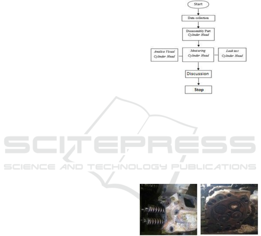
2.3 Research Diagram
This study aims to determine whether the QSK 50
MCRS cylinder head analysis still meets the
standards with the manual and to find out how to
minimize damage to the cylinder head. The stages in
analyzing the damage can be seen in the image
below.
Figure 1: Research diagram.
3
RESULTS AND DISCUSSION
3.1 Cylinder Head Disassembly
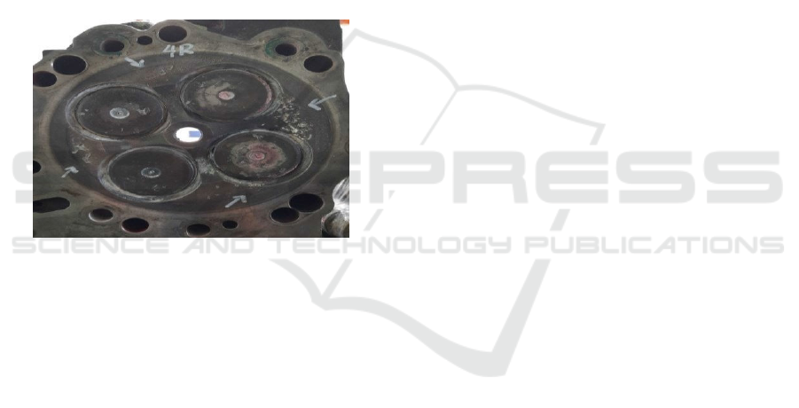
From initial observations made on the QSK 50
MCRS cylinder head engine, it shows that the hour
meter unit is 14,000 HM. The cylinder head is
damaged on the surface of the combustion chamber,
due to erosion.
Figure 2: Corrosion on cylinder head.
During the process of dismantling from the
cylinder head on the QSK 50 MCRS engine.
Actually, evidence was found that the right side of
the combustion chamber surface was eroded.
Therefore the cylinder head must be disassembled
and then re- inspected to ensure the actual
specifications on the cylinder head.
3.2 Disassembly Valve
One of the aims is to remove the components in the
iCAST-ES 2021 - International Conference on Applied Science and Technology on Engineering Science
374
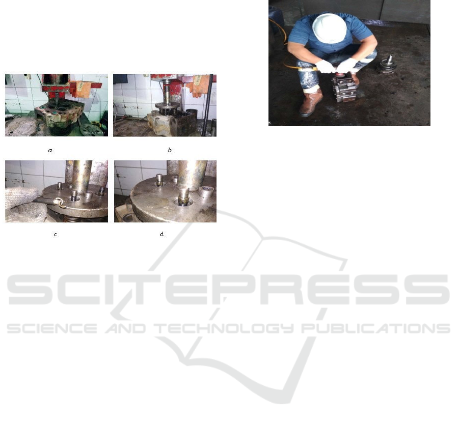
cylinder head such as valve, spring valve, cotter, and
retainer. The tools and materials used are as follows:
▪
Tools used: hydraulic press, magnetic tool,
valve spring tool
▪
Materials used: majun
Safety used: safety helmet, safety shoes, safety
goggles, hand gloves.
Figure 3: Disassembly valve.
Information:
a)
Place the cylinder head under the hydraulic
press,
b)
valve spring device above the retaining valve,
c)
Then press the valve spring tool with a
hydraulic press. When Cotter is seen, take it
using the magnetic tool,
d)
After the cotter is removed, the retainer, valve
spring, and valve can be removed.
3.3 Cleaning Process
In this step the cylinder head will be cleaned of
dirt/dirt adhering to the components and cleaned of
rust and oil adhering to the cylinder head. Because
the slightest will affect the results of the
measurements later. Figure 3 shows the process of
inserting the cylinder head into the hot tank to
remove the remnants of dirt/soil, paint, rust. Shows
the spraying process on the cylinder head and
grinding process uses an air angle grinder with a
steel wire brush.
This process requires tools such as diesel fuel,
gasoline, brushes, Scocth Brite, cloth cloth, air angle
grinder, soap and hot tanks to facilitate cylinder head
repair. After cleaning the cylinder head and smeared
with a little diesel as an outer coating to prevent rust
on the cylinder head. These steps are carried out to
simplify the measurement process in order to get
actual results from the measurement process.
Figure 4: Inserting the cylinder head into the hot tank.
3.4 Visual Cylinder Head Analysis
During the cleaning process, components were
found to be damaged in part of each surface of the
combustion chamber on the cylinder head. The
characteristics of the damage can be indicated that
there has been "erosion" on the surface of the
combustion chamber, and erosion on the surface of
the combustion chamber due to air bubbles or
exploding during the power stroke of the four stroke
engine cycle. Erosion is characterized by a surface
with small holes. The phenomenon of the shrinkage
porosity defect is caused by the inclusion of
aluminum oxide carried into the Cylinder Head
Type- A product which is the initiation of the
formation of shrinkage porosity. The presence of
aluminum oxide in Cylinder Head Type-A products
is caused by the relatively long transfer of melting
time from the smelting furnace and the relatively
high auto carrier distance, which also affects the
furnace pouring time. (Wahyudi and Wiryolukito
2020).
When these bubbles enter an area of high
pressure, they burst (explode inward) sending a
"beam" of liquid hitting the metal surface at
supersonic speeds. Minor cracks sometimes occur
and coalesce until a small portion of the metal
particles is released and results in holes in the
component.
Deep pitting/pitting on the liner surface is the
result of cavity erosion. The damage could
accumulate in one area of the liner wall only.
Actually, at the time of revelation stated that the
damaged area was located between the cylinder head
and the liner surface.
The aluminum housing of the cooling system can
be damaged by cavitary erosion, especially if there is
obstruction in the intake/inlet line which results in a
Analysis Damage Cylinder Head Engine on QSK 50 MCRS
375
low pressure and subsequently cavitation of the fluid
in the pump impeller. Bubbles (bubbles) are formed
on the low pressure side (suction/suction). It will
burst on the high pressure side (exhaust/exhaust).
Using of filler metal in the powder thermal spray
technique. This technique is still different, and the
joining category is included in the dissimilar metal.
Therefore, an important problem that must be solved
is how to repair casting defects by eliminating repair
weaknesses with the methods that have been
developed (Permana, Suratman et al.).
3.5 Actual Data Measurement
Before starting the measurement, a manual is needed
to know the measurement procedure and the
specifications of the component itself. In this
process, several measuring instruments are needed to
obtain maximum measuring results. The measuring
instruments used in measuring cylinder head are as
follows:
1.
Vernier digital caliper
2.
Call Indicator
The general procedure in the manual for
inspecting and repairing cylinder heads is as follows:
1.
Clean the cylinder head from adhering dirt such
as (soil, paint, and rust marks) attached,
2.
Measure the length, thickness, and indentation
(pitting) of the cylinder head,
3.
Check the combustion chamber area for cracks
and leaks,
4.
Inspect the burning area for damage or erosion,
5.
Repair of components that require repair and
replacement of parts that do not meet
specifications.
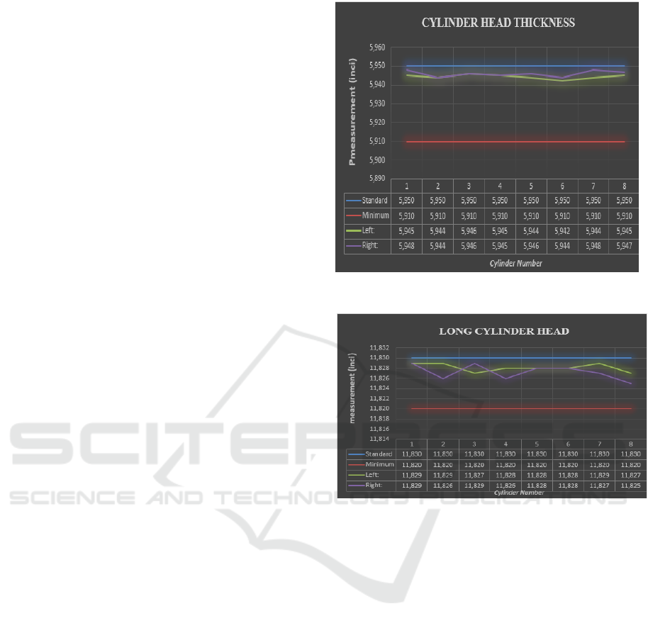
3.5.1 Cylinder Head Thickness and Length
This measurement is done so that the results
obtained can be compared with the manual and to
detect damage visually. Because damage to this area
can have a major impact on engine performance.
The impact of damage to this area includes
compression compression, the entry of oil into the
combustion chamber, which results in incomplete
combustion. In the measurement step, a digital
caliper is used. The measurement results can be seen
in the image below. Based on the data in Figure 5,
the cylinder head thickness still meets the standard
measurement results are still above the standard
because the cylinder head thickness is minimum.
Figure 5: Cylinder head thickness measurement results.
Figure 6: Cylinder head length measurement results.
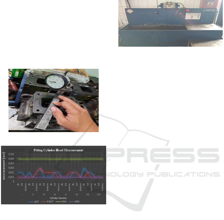
3.5.2 Cylinder Head Thickness and Length
High pressure and temperature in engine operation
can cause changes in the shape of the cylinder head
surface, usually in the form of indentations or
depressions on the cylinder head surface. Therefore,
it is necessary to measure the pitting cylinder head.
This is to check the flatness of the cylinder head
surface. Because the density of each combustion
chamber in the cylinder head greatly affects the life
and performance of the engine itself. If there is
pitting on the surface of the cylinder head that
occurs too far from the specifications, it will result
in fatal damage, namely:
1.
Coolant will enter the lubrication system so
that the lubricant will not working properly as
it should.
2.
There is a compression leak so that the
compressed air will enter the cooling system or
vice versa which can result in a hydraulic
block in the combustion chamber and cause
iCAST-ES 2021 - International Conference on Applied Science and Technology on Engineering Science
376
more severe damage.
3.
Damage the components in the cylinder head
due to changes position.
This measurement uses a dial indicator and a
straight edge. The surface of the cylinder head that
experiences high pressure and temperature is
measured for flatness, then the measurement results
will be compared with the standards in the manual to
determine whether the cylinder head can still be
used, requires repair or needs to be replaced with a
new one.
Figure 7: Pitting measurement on cylinder head.
Figure 8: Pitting measurement results on the cylinder
head.
Figure 8 shows the results of pitting
measurements on the cylinder head. The
measurement results indicate that the cylinder head
still meets the standard and can be reused, the hole
measurement value is still below the maximum
value.
3.5.3 Leak Test (Pressure Test Cylinder
Head
The purpose of the cylinder head leak test is to
check whether the cylinder head is leaking or not, so
that it can determine the pressure (pressure) of the
cylinder head. Figure 4.15 shows the tank pressure
test used for the cylinder head leak test.
Figure 9: Tank pressure test.
In testing the cylinder head leak, several stages
are carried out, namely:
1.
The bottom surface hole is tightly closed using a
good platform for testing to prevent air from
escaping.
2.
Using compressed air of about 100 psi (pounds
per square inch).
3.
Using a cylinder head pressure tester.
This method is done by inserting the cylinder
head into the air and then applying air pressure.
After testing, the results showed that there was
no leakage at the orifice valve. In addition to the
pressure test, a visual inspection of the cylinder head
is also carried out to check:
1.
Broken bolts / studs.
2.
Corrosion of hose connections.
3.
Oil leaks.
4.
The vacuum hose hose is damaged / missing.
5.
Coolant leaks.
3.6 Burn Area Analysis of Damage
In this step a visual inspection of the combustion
area should be carried out to check for damage and
erosion. Erosion of these areas will have a negative
effect on engine performance. Checkpoints for
erosion are shown in Figure 10. Check areas that are
suspected of being damaged and eroded,
namely:(16) firering (combustion chamber area);
(17) seating area; (18) the area between the injector
nozzle orifice and the valve seat. Erosion in other
areas of the surface may occur but will not affect the
operation of the machine.
During the cleaning process, components were
found to be damaged each surface of the combustion
chamber on the cylinder head. The characteristics of
the damage indicates that there has been "erosion"
on the surface of the combustion chamber, erosion
on the surface of the combustion chamber due to air
bubbles that burst or explode during the power
stroke of the engine's four stroke cycle. Erosion is
characterized by a surface with small holes.
Analysis Damage Cylinder Head Engine on QSK 50 MCRS
377
When these bubbles enter an area of high
pressure, they burst (explode inward) sending a
"beam" of liquid hitting the metal surface at
supersonic speeds. Minor cracks sometimes occur
and coalesce until a small part of the metal particles
is released and results in holes in the component.
Deep pitting/pitting on the liner surface is the
result of cavity erosion damage accumulates in one
area of the liner wall only. The facts at the time of
revelation stated that the damaged area was located
between the cylinder head and the liner surface.
The aluminum housing of the cooling system can
be damaged by cavitary erosion, especially if there is
obstruction in the intake/inlet line which results in a
low pressure and subsequently cavitation of the fluid
in the pump impeller. Bubbles (bubbles) formed on
the low pressure side (suction/suction) will burst on
the high pressure side (exhaust/exhaust). Figure 10
shows erosion on the cylinder head.
Figure 10: Erosion on cylinder head.
4 CONCLUSIONS
Based on and discussion in research regarding
Cylinder Head Damage Analysis on the QSK 50
MCRS Engine, it is obtained as follows.
1.
Analysis of the 16 cylinder heads of QSK 50
MCRS shows that all cylinder heads can still
be reused, because the cylinder heads are still
within the standard range that has been set in
the manual.
2.
For longer cylinder head use, it is better to
prevent more fatal damage by performing
regular servicing. Therefore, in the assembly
process and maintenance of the cylinder head is
important and in the assembly process must be
in accordance with the procedures set out in the
manual.
ACKNOWLEDGEMENTS
There are many obstacles in completing this
research, and this work would not have been
possible without the support of several parties.
For that, I would like to thank all parties who
have been willing to work so far and other related
writings. Director of the Nunukan State Polytechnic
who has provided support to me in completing this
research.
I also want to thank my family and friends who
have always supported me in completing this
research.
REFERENCES
Hutama, V. I. (2019). Analisis Penyebab Terjadinya
Kebocoran Air Di Ruang Pembakaran Pada Diesel
Generator Di Km. Spil Nita (Doctoral dissertation,
Politeknik Ilmu Pelayaran Semarang).
Moore, R., & Lopes, J. (1999). Paper templates. In
TEMPLATE’06, 1st International Conference on
Template Production (pp. 319-340).
Nasution, S., & Razali, R. (2019, December). Analisa
Kegagalan Cylinder Head Mesin Diesel Komatsu
dengan Menggunakan Metode Failure Mode and
Effect Analysis (Fmea) Dimegapower Pltd Bengkalis.
In Seminar Nasional Industri dan Teknologi (pp. 236-
242).
Permana, M. S., Suratman, R., & Tarigan, B. Bagaimana
Memperbaiki Cacat Permukaan Pada Komponen Yang
Terbuat Dari Besi Cor.
Ricky, M. Y. (2014). Mobile food ordering application
using android os platform. In EPJ Web of Conferences
(Vol. 68, p. 00041). EDP Sciences.
RIKI, A. (2019). Perbaikan Silinder Head Pada Mesin A/E
Caterpillar C7 Pt. Samudera Indonesia. Karya Tulis.
Wahyudi, W., & Wiryolukito, S. (2020). Analisis Gagal
Leak Test Pada Produk Cylinder Head Type-A Hasil
Proses Low Pressure Die Casting Dengan Material
Ac4b Di Pt. X. Technologic, 11(2).
Wibowo, E. P., Zondra, E., & Situmeang, U. (2018). Studi
Penggunaan Variable Speed Drive Untuk Pengaturan
Kecepatan Motor Exhaust Fan Pada Dyno Test Room
PT. Trakindo Utama Pekanbaru. Jurnal Teknik, 12(2),
85-96.
iCAST-ES 2021 - International Conference on Applied Science and Technology on Engineering Science
378
