
Mini Pile Foundation Construction Design on Soft Soil Due to Box
Traffic Loads based on Standard Penetration Test
Liliwarti, Dwina Archenita and Sandra Faurina
Civil Engineering Department, Politeknik Negeri Padang, Limau Manis, Padang, Indonesia
Keywords: Box Traffic Loads, Mini Pile Foundation, Foundation Construction Design.
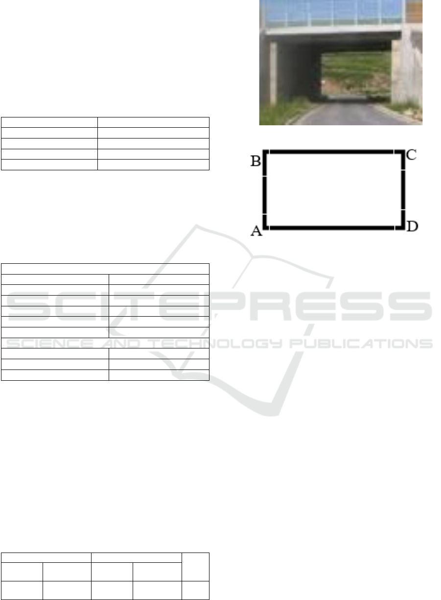
Abstract: Box traffic is an underpass structure in the form of a tunnel under the ground that functions as a transverse
road under other roads that serves as a liaison between separate areas due to the construction of toll roads.
The construction of Padang – Sicincin Toll Road has separated several surrounding areas so that public access
is limited. To solving this problem, a traffic box is built at STA 2+175. Based on the Standard Penetration
Test (SPT) data, the location has deep soft soil, so that it cannot support the loads. This paper discusses the
used of mini pile foundations to increase the bearing capacity of the soil. The foundation was used with a size
of 0.25 m x 0.25 m, the distance between the piles (s) 1m, with variations in the penetration depth of 10m,
12m, and 14m. Bearing capacity analysis was carried out based on SPT data. The analysis results show that
the sub-grade settlement without using a mini pile foundation is 0.34 m – 0.35 m BH-01 and 0.59 m – 0.62 m
on BH-02, where the settlement exceeds the allowable settlement limit. While, by using a mini pile foundation
with a depth of 10 m, the settlement is 0.02 – 0.05 cm. This settlement is smaller than the allowable settlement
for pile foundation. The bearing capacity of the mini pile group foundation increases with increasing pile
penetration depth, but it does not apply to single piles.
1 INTRODUCTION
Pile foundation is one of the important aspects of road
construction. It functions as a successor to the load
that works on it and is channeled to the subgrade. Pile
foundations are generally divided into two sizes,
namely large size (maxi pile) and small size (mini
pile)(Yu & Wang, 2019). The foundation must
withstand the loads that work on it (Yu & Wang,
2019), (Purwanto, 2019). One of these loads can be a
box traffic load.
Box traffic is an underpass structure in a tunnel
under the ground that functioned as a transverse road
under the road (Desai & Desai, 2017). In its role as an
underpass, this traffic box carries both gravity and
lateral loads. The gravity load includes dead loads and
live loads. In comparison, the lateral load includes
earth pressure and earthquake loads (Wrana, 2015),
(de Sanctis et al., 2021). Carry out the working load
needs the subgrade must have allowable bearing
capacity to withstand the load.
In the construction of the Padang-Sicincin Toll
Road, there is a location with soft soil that is quite
deep based on the Standard Penetration Test results
(SPT). This condition leads to the soil not being able
to withstand the load, such as box traffic. Therefore,
efforts are needed to increase the bearing capacity of
the soil.
This paper discusses a mini pile foundation design
due to box traffic load to solve the problem. This
foundation design will strengthen the subgrade of the
structure. Thus, it has sufficient permit-bearing
capacity to withstand the load.
This paper is organized as follows: In Section 2,
the proposed construction design is explained.
Section 3 contains the results and discussion of the
methods that have been implemented. Lastly, section
4 concludes the paper.
2 METHODS
2.1 Data Collection
The mini pile foundation construction design is built
from secondary data, i.e., the soil data from field and
laboratory tests, box traffic structure specification,
and mini pile specification data.
358
Liliwarti, ., Archenita, D. and Faurina, S.
Mini Pile Foundation Construction Design on Soft Soil Due to Box Traffic Loads based on Standard Penetration Test.
DOI: 10.5220/0010945800003260
In Proceedings of the 4th International Conference on Applied Science and Technology on Engineering Science (iCAST-ES 2021), pages 358-364
ISBN: 978-989-758-615-6; ISSN: 2975-8246
Copyright
c
2023 by SCITEPRESS – Science and Technology Publications, Lda. Under CC license (CC BY-NC-ND 4.0)
2.1.1 Soil Data
Field testing: boring and SPT tests of two
drilling points (BH-01 and BH-02) with a depth
of 50 m
Laboratory test: from 4 undisturbed sample
(UDS1 to UDS4) which varies in-depth, as
shown in Table 1.
Table 1: Undisturbed Samples for Soil Laboratory Test.
Sam
p
le ID De
p
th
UDS1 5 m and 13
m
UDS2 19 m an
d
29
m
UDS3 39
m
UDS4 49
m
2.1.2 Box Traffic Specification
The traffic box specifications used are shown in Table
2. With concrete quality, the density of concrete and
steel quality is 20 MPa, 24 kN/ m
3
, and 390 MPa.
Table 2: Box Traffic Specification.
Dimension
Len
g
th 32,70
m
Width 970 or 974 m (skew)
Height 6.95
m
Top plate thickness 0.80
m
Wall
p
late thickness 0.85
m
Bottom
p
late thickness 0.95
m
Materials
Concrete qualit
y
20 MPa
Density of concrete 24 kN/ m
3
Steel
q
ualit
y
390 MPa
2.1.3 Mini Pile Specification
The mini pile is 0.25x 0.25 m in size. It is calculated
with the condition of the head of the pile being
pinched. It is because the thickness of the bottom
plate of the box is directly used as a pile cap.
2.2 Box Traffic Loads
The box traffic load for the foundation construction
design is shown in Table 3. While R
A
is reaction at
point A, R
D
is reaction at point B, and Q is load.
Table 3: Box Traffic Load.
R
A
R
D
Q
(kN)
Vertical
(kN)
Horizontal
(kN)
Vertical
(kN)
Horizontal
(kN)
6927.51 -3.02 8109.50 0
1503
7.01
Figure 1: Box Traffic.
Figure 2: The points reviewed on the box traffic.
2.3 Mini Pile Foundation Construction
Design
The mini pile foundation is designed with a direct
foundation plate like a pile cap from the pile head
(foundation with a box traffic monolith structure) (Yu
& Wang, 2019). Thus, the head of the foundation is
in a clamped condition. It means that it can withstand
the moment or overturn in the structure or the moment
on the structure=0. Manual calculations carry out this
foundation design for the axial bearing capacity of the
pile foundation and the bearing capacity of the group
pile foundation. At the same time, the lateral bearing
capacity of pile foundations and pile foundation
settlement is modeled using structure analysis
software.
The calculations of three factors can determine the
number of piles, i.e. (1) the distance between the piles
(s) following the box traffic structure; (2) the
implementation of pile driving in the field; (3) the
efficiency of the pile group (de Sanctis et al.,
2021),(Feicheng & Jianjing, 2017). Based on these
factors, the distance between the piles is 1 m with the
pile group efficiency is 0.75 for cohesive soils based
on the group pile efficiency factor in cohesive soils
While for non-cohesive soils is 1. Thus, the number
of piles (n) that will be used is 279 piles and the cross-
section as shown in Fig.3.
Mini Pile Foundation Construction Design on Soft Soil Due to Box Traffic Loads based on Standard Penetration Test
359

Figure 3: Mini pile foundation design based on the distance
between the piles (s) is 1.
2.3.1 Loads on Foundation
Total loads on pile group (P
total
), is calculated
by the Eq 1.
𝑃
𝑅
𝑅
While,
R
A
= Reaction at point A (kN)
R
D
= Reaction at point D (kN)
The loads on each pile (P
single
), is calculated
from the P
total
divided by the number of pile
(n), as shown in Eq.2.
𝑃
These calculations give P
total
= 15037.01 kN, and
P
single
= 53.89kN.
2.3.2 Axial Bearing Capacity of Pile
Foundation
The axial bearing capacity of the pile foundation is
calculated based on the strength of the material and
soil conditions around the foundation (Liliwarti,
2019). The calculations is done at a depth of 10 m, 12
m, and 14 m. This aims to determine whether the pile
is able to withstand the loads both internally and
externally
Axial bearing capacity of pile foundation based on
SPT
The axial bearing capacity of the pile foundation
from the SPT data is calculated using an equation
based on the Meyerhof 1956 method (Hardiyatmo,
2011).
a. End Bearing Pile
- End Bearing Pile in cohesive soil
𝑄
𝑝
9 𝑥 𝑐
𝑢
𝑥 𝐴
𝑝
(3)
- End Bearing Pile in cohesive soil
Q
40 x N
x
x A
400 x A
x N
(4)
b. Friction pile
- cohesive soil
Q
α x c
x p x L
(5)
- Non cohesive soil
Q
s
2 x N
SPT
x p x L
i
(6)
- Total Bearing Capacity
Q
u
QpQs (7)
Where
Q
p
: friction pile (kN)
𝑁
𝑆𝑃𝑇
: N- SPT
c
u
: undrained cohesion (kN/m
2
)
L : dept of pile (m)
d : diameter of pile (m)
A
p
: area of pile (m
2
)
Q
s
: tahanan gesek tiang (kN)
α : coeficient adhesi soil and pile
p : perimeter of pile (m)
L
i
: dept of soil layer (m)
2.3.3 Lateral Bearing Capacity of Pile
Foundation
Pile foundation in the box traffic is designed with the
condition of the pile head pinched (Hardiyatmo,
2011). Thus, it can withstand the moment that will
occur (moment = 0). Lateral load on the foundation
based on structural mechanics is analyzed by using
analyzing software. It gives the result of 3.02 kN (H
= 3.02 kN). Furthermore, the lateral bearing capacity
of the pile foundation against the load is calculated
based on variations in the depth of pile penetration,
i.e., 10 m, 12 m, and 14 m.
The type of soil at the tip of the pile in each
variation of penetration depth in BH-01 and BH-02
includes silt and/or sandy soil. Therefore, based on
Broms's (1964) method in calculating the lateral
bearing capacity of the pile, the formula used is a
formula that is suitable for the type of soil at the end
of the pile, i.e., silt and or sand. The lateral bearing
capacity of the pile is calculated based on the pile
deflection and the ultimate lateral load-bearing
capacity that the pile can withstand (Hardiyatmo,
2011).
The ultimate lateral load of the pile is calculated
based on Broms method (1964) (Hardiyatmo, 2011).
Calculation of the pile type obtained from the previous
calculation pile vertical deflection and the type of soil
at the tip of the pile in BH-01 and BH-02. The
calculations result are shown in Table 4.
iCAST-ES 2021 - International Conference on Applied Science and Technology on Engineering Science
360
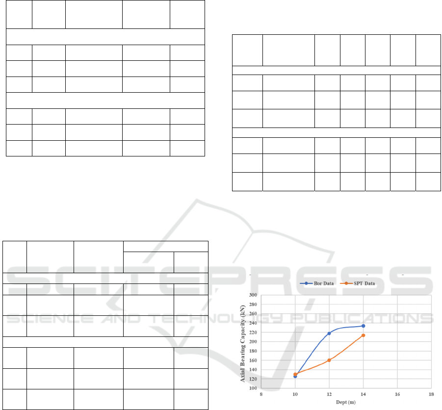
Table 4: The ultimate lateral load-bearing capacity of the
pile on BH-01 and BH-02.
No. Depth Soil type
My
(kN-m)
Hu
(kN)
BH-01
1 10 m Silt 25.34 22.52
2 12 m Sandy silt -173.39 -127.26
3 14 m Sandy silt -250.17 -158.84
BH-02
1 10 m Silt sand 1492.05 799.32
2 12 m Sandy silt -278.62 -201.54
3 14 m Sandy silt -311.37 -196.14
Hardiyatmo (2011),(Hardiyatmo, 2011) states
that the maximum deflection for buildings, bridges,
and similar structures is 6 mm to 18 mm. Vertical pile
deflection from the analysis is shown in Table 5.
Table 5: Vertical pile deflection on BH-01 and BH-02.
No.
Penetrati
on depth
Soil
types
yo (m)
Cohesive
Gran
ular
BH-01
1 10 m Silt 0.00169 -
2 12 m
Sandy
silt
0.00143 -
3 14 m
Sandy
silt
0.00125 -
BH-02
1 10 m
Silt
san
d
- 8E-05
2 12 m
Sandy
silt
0.00111 -
3 14 m
Sandy
silt
0.00101 -
2.3.4 Pile Settlement
The total settlement that occurs in the pile foundation
is calculated based on the elasticity of the pile
material itself and the axial bearing capacity of the
pile (Wang et al., 2019), (Hardiyatmo, 2011). The
axial bearing capacity of the pile under review is the
carrying capacity based on SPT data on BH-01 and
BH-02. So that the pile settlement will be calculated
based on these two indicators, in addition, pile
settlement will also be calculated for each variation
of pile penetration depth on BH-01 and BH-02. The
settlement on the pile was calculated based on the
Vesic method (1977) according to the magnitude of
the axial bearing capacity of the pile based on SPT
data. The calculations result are shown in Table 6.
Table 6. The Total Pile Group Settlement on BH-01 and
BH-02.
Dept
h
Soil type
S
1
(cm
)
S
2
(cm
)
S
3
(cm
)
s
(cm
)
S
g(e)
(cm
)
BH-01
10 m
Silt 0.01 0.00 0.00 0.01 0.04
12 m
Sandy
sil
t
0.01 0.00 0.00 0.01 0.04
14 m
Sandy
sil
t
0.01 0.00 0.00 0.01 0.05
BH-02
10 m
Silt sand 0.01 0.00 0.00 0.01 0.05
12 m
Sandy
sil
t
0.01 0.00 0.00 0.01 0.05
14 m
Sandy
sil
t
0.01 0.00 0.00 0.01 0.05
3 RESULT AND DISCUSSION
Based on the previous calculation, the result of the
0.25 x 0.25 m mini pile foundation construction
design is obtained, as shown in Fig. 2 to Fig. 9.
Figure 4: Axial bearing capacity single pile on BH-01.
Bearing capacity on BH-01 increases with the
dept of the pile, showing the deeper the pile driving,
the greater the bearing capacity of the soil.
Mini Pile Foundation Construction Design on Soft Soil Due to Box Traffic Loads based on Standard Penetration Test
361
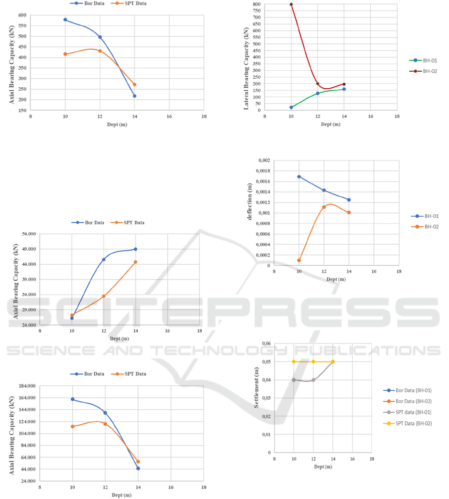
Figure 5: Axial bearing capacity single pile on BH-02.
Bearing capacity on BH-02 decreases with the
dept of the pile, showing the deeper the pile driving
the lower bearing capacity of the soil. This is because
of the condition of the soil layer at a depth of 12 and
14 m in soft soil.
Figure 6: Bearing capacity of the pile group on BH-01.
Figure 7: Bearing capacity of the pile group on BH-02.
Bearing capacity for single piles and group piles
shows the same behavior in BH01 and BH 02.
Figure 8: Lateral load capacity on BH-01 and BH-02.
Figure 9: Maximum pile deflection on BH-01 and BH-02.
At BH01, the pile deflection decreases with
increasing depth of the pile, but otherwise for BH 02.
Figure 10: Pile settlement on BH-01 & BH-02.
Pile settlement BH 01 and BH02 showed the same
results in analysis with bor data. If analyzed with SPT
data, there was an increase in the value of pile
settlement, but still below the allowable settlement.
Based on the design calculations that have been
carried out, the mini pile foundation is planned with a
pile penetration depth (L) of 10 m, the distance
between piles (s) of 1 m, and the number of pile
foundation points (n) as many as 279 piles. It is
obtained based on the calculation output of the
permitted axial bearing capacity, group bearing
iCAST-ES 2021 - International Conference on Applied Science and Technology on Engineering Science
362
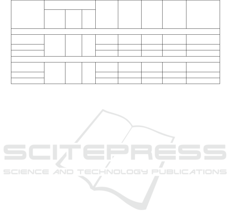
Table 7: The final result design of the mini pile foundation varies in-depth on BH-01 and BH-02.
Loads Acting on the
Foundation
Pile Axial
allowable
Bearing
Capacity
(Q
all
)
(kN)
Pile
Group
allowable
Bearing
Capacity
(Q
ag
) (kN)
Ultimate
Lateral
Load
(Hu)
(kN)
Pile
Deflection
(yo)
(m)
Settlement of
Pile
(S
g(e)
) (cm)
P
total
(kN)
P
tunggal
(kN)
H
(kN)
BH-01
Depth of Pile
10 m
15037.01 53.89 3.02
130.27 27258.6
22.52 0.002 0.04
Safety Factor
2.5 2.5
2.5 0.025
6.5
Safe Safe Safe Safe Safe
BH-02
Depth of Pile
10 m
15037.01 53.89 3.02
415.64 115963.6
799.32 0.0001
0.05
Safety Factor
2.5 2.5
2.5 0.025
4.0
Safe Safe Safe Safe Safe
capacity, lateral bearing capacity, and pile settlement
at a depth of 10 m based on SPT data that can
withstand the load that will work. The final result in
a mini pile foundation design for the traffic box is
shown in Table 7.
4 CONCLUSION
Based on the calculations that have been carried out,
the mini pile foundation is planned with a pile
penetration depth (L) of 10 m, a distance between
piles (s) of 1 m, and the number of pile foundation
points (n) as many as 279 piles. It is obtained based
on the calculation results of the permit axial bearing
capacity, group bearing capacity, lateral bearing
capacity, and pile settlement at a depth of 10 m based
on SPT data. It has been able to withstand the load,
and the load on the single pile (P
single
) and the pile
group (P
total
) is 53.89 kN and 15037.01 kN. The
magnitude of the decrease in the pile group that
occurs is 0.02 – 0.05 cm. It shows that the settlement
is safe for the structure because it does not exceed the
maximum pile settlement limit, which is 6.5 cm for
piles in clay and 4.0 cm for piles in the sand (SNI
8460:2017).
In further research, the calculation of the load on
the subgrade originating from the box traffic structure
load is expected to be closer to the original conditions
in the field so that the subgrade settlement due to the
working structure load can be calculated more
accurately. complete again so that the calculation of
settlement and foundation design can run smoothly
and have more accurate results.
ACKNOWLEDGMENTS
This research was fully funded by DIPA of
Politeknik Negeri Padang.
REFERENCES
de Sanctis, L., Di Laora, R., Maiorano, R. M. S., Favata, G.,
& Aversa, S. (2021). Failure envelopes of pile groups
under combined axial-moment loading: Theoretical
background and experimental evidence. Soils and
Foundations, xxxx.
https://doi.org/10.1016/j.sandf.2021.08.002
Desai, S., & Desai, A. (2017). International Journal of
Technical Innovation in Modern Engineering &
Science ( IJTIMES ). 3(5), 43–48.
Feicheng, L., & Jianjing, Z. (2017). A Simplified Method
for Pile- Supported Embankment Reinforced With
Geosynthetic over Soft Soil and the Influence of Design
Parameters. Electrical Journal of Geotechnical
Engineering, 22(07), 2545–2578.
Hardiyatmo, H. C. (2011). Analisa dan Perancangan
Fondasi II. Gadjah Mada University Press.
Liliwarti, L.-. (2019). Peningkatan Nilai CBR Tanah Dasar
(Sub Grade) dengan Penambahan Kapur dan Abu
Sekam Padi. Jurnal Ilmiah Poli Rekayasa, 14(2), 24.
https://doi.org/10.30630/jipr.14.2.124
Purwanto, E. (2019). Technology of mini piles for high
embankment stability on soft soils to prevent a
settlement. International Journal of Advanced
Research in Engineering and Technology, 10(6), 224–
233. https://doi.org/10.34218/IJARET.10.6.2019.026
Wang, Z., Hu, Z., Lai, J., Wang, H., Wang, K., & Zan, W.
(2019). Settlement Characteristics of Jacked Box
Tunneling underneath a Highway Embankment.
Journal of Performance of Constructed Facilities,
Mini Pile Foundation Construction Design on Soft Soil Due to Box Traffic Loads based on Standard Penetration Test
363

33(2), 04019005. https://doi.org/10.1061/
(ASCE)cf.1943-5509.0001269
Wrana, B. (2015). Pile Load Capacity – Calculation
Methods. Studia Geotechnica et Mechanica, 37(4), 83–
93. https://doi.org/10.1515/sgem-2015-0048
Yu, X., & Wang, X. (2019). Research on the Design of
Miniature Pile Foundation for Transmission Line. E3S
Web of Conferences, 136, 2–5.
https://doi.org/10.1051/e3sconf/201913602022
iCAST-ES 2021 - International Conference on Applied Science and Technology on Engineering Science
364
