
Experimental Study of the Effect of Excitation Current on the Output
Voltage of a Self-excited Synchronous Generator
Anggara Trisna Nugraha
a
and Alwy Muhammad Ravi
Department of Marine Electrical Engineering, Shipbuilding Institute of Polytechnic Surabaya, Jl. Teknik Kimia,
Kampus ITS Sukolilo, Surabaya (60111), Indonesia
Keywords: Synchronous Generator, Excitation System, and Self-excitation.
Abstract: Energy needs continue to increase. Currently, the demand for electrical energy is growing at a higher rate than
other energies. Based on Energy Outlook 2019, coal-fired power generation still dominates. However, if no
new coal reserves are found, then medium to high-quality coal reserves are projected to be exhausted in 2038.
To meet the need for electrical energy, it is necessary to utilize the energy available in nature optimally and
stable with changes in electrical load. The potential for hydro energy that can be utilized to generate electricity
is 75,901 MW. Generators in a power plant have an important role as a converter of mechanical energy into
electrical energy to be utilized. However, to be able to use the stability of the electrical energy produced needs
to be considered. One way to stabilize the output voltage of a generator can be done by adjusting the excitation
current value. Therefore, the purpose of this study is to determine the effect of the self-amplifying excitation
system on a synchronous generator on the output voltage produced when there is no electrical load and an
electrical load. The test results show that the excitation current greatly affects the output voltage of the
synchronous generator. The hope of this research can be applied to the prototype of the vortex turbine pico
hydropower plant which is currently being researched as well.
1 INTRODUCTION
Energy has an important role in supporting human
life. Along with the times, energy needs continue to
increase (Baskoro & Adiwibowo, 2017). Currently,
the demand for electrical energy is growing at a
higher rate compared to other energies (Team
Secretary-General of the National Energy Council,
2019). Based on Energy Outlook 2019, coal-fired
power generation still dominates. However, if no new
coal reserves are found, then medium to high-quality
coal reserves are projected to be depleted in 2038
(Agency for the Assessment and Application of
Energy, 2018). To meet the needs of electrical energy,
it is necessary to utilize the energy available in nature
optimally and stable with changes in electrical loads.
Indonesia is very rich in its renewable energy
potential. One of the renewable energy that can be
used as electrical energy is hydro energy. Based on
Indonesia's clean energy status report, the potential
for hydro energy that can be utilized to generate
electricity is 75,091 MW (Tampubolon & Adiatama,
a
https://orcid.org/0000-0002-4482-2829
2019). The utilization of hydro energy into electrical
energy in a simple form is mostly obtained from the
application of hydropower plants with pico and micro
scales.
In a previous study conducted by Pambudi (2020),
he has designed a laboratory-scale micro-hydro
power generation system by utilizing an induction
generator and a permanent magnet generator
(synchronous generator) to compare the output of
electrical power generated. The results of this study
indicate that a permanent magnet generator
(synchronous generator) has an optimal efficiency
and power output of 195.3 watts with an efficiency of
89%. However, power plants can be utilized, if the
output of electrical energy is stable due to changes in
electrical load.
In another study conducted by (Syahputra, 2012),
examined the effect of a synchronous generator
voltage stabilizer system using a separate amplifier
excitation system. The test results show that the
synchronous generator output voltage is greatly
affected by the size of the excitation current.
86
Nugraha, A. and Ravi, A.
Experimental Study of the Effect of Excitation Current on the Output Voltage of a Self-excited Synchronous Generator.
DOI: 10.5220/0010940500003260
In Proceedings of the 4th International Conference on Applied Science and Technology on Engineering Science (iCAST-ES 2021), pages 86-93
ISBN: 978-989-758-615-6; ISSN: 2975-8246
Copyright
c
2023 by SCITEPRESS – Science and Technology Publications, Lda. Under CC license (CC BY-NC-ND 4.0)

However, the application of an excitation system with
a separate amplifier is not possible if it is applied to a
prototype of a pico hydropower plant that utilizes
hydro energy directly in the river because the
excitation system is easy to implement, namely
utilizing a rectified generator output voltage for an
excitation source for the synchronous generator itself.
Therefore, in this study, we will utilize a self-
amplifying excitation system resulting from
rectifying the AC power output from the synchronous
generator into DC electricity, then stored in the
battery as an excitation supply to the synchronous
generator. The purpose of this study is to determine
the effect of the self-amplifying excitation system on
a synchronous generator on the output voltage
produced when there is no electrical load and an
electrical load. The hope of this research can be
applied to the prototype of the vortex turbine pico
hydropower plant which is currently being researched
as well.
2 MATERIALS AND METHODS
2.1 Excitation System
The excitation system is a system of flowing direct
current electricity supply as a reinforcement to the
electric generator so that it produces electric power
and the output voltage depends on the amount of
excitation current (Nurdin et al., 2018). The generator
excitation system is an important element to form a
stable generator terminal voltage profile. The
operating system of this generator excitation unit
functions to keep the generator voltage constant
(Fahmi & Irwanto, 2020). One of the excitation
systems in an electric generator is an excitation
system using a brush.
The excitation system uses a brush (brush
excitation), the source of electric power comes from
a power source that comes from a direct current (DC)
generator or an alternating current (AC) generator
which is rectified first using a rectifier. If you use a
power source that comes from an AC generator or
permanent magnet generator (PMG), the magnetic
field is a permanent magnet. In the rectifier cabinet,
alternating current is converted or rectified into direct
current voltage to control the main exciter field coil.
To drain the excitation current from the main exciter
to the generator rotor using slip rings and charcoal
brushes (Nurdin et al., 2018).
The use of slip rings and brushes, usually used in
small-capacity generators. This spring is made of
metal which is usually attached to the engine shaft but
is isolated from the shaft. Where the two ends of the
field winding on the rotor are connected to the slip
ring. By connecting the positive and negative
terminals of the direct current source to the slip ring
through the brush, the field winding will get a supply
of direct current electrical energy from an external
source (Fahmi & Irwanto, 2020).
2.2 Synchronous Generator
An alternating current (AC) generator or also known
as an alternator is a device that functions to convert
mechanical energy (motion) into electrical energy
(electrical) by means of magnetic field induction.
This energy change occurs due to a change in the
magnetic field in the armature coil (where the voltage
is generated in the generator). It is said to be
synchronous generator because the number of
rotations of the rotor is equal to the number of
rotations of the magnetic field on the stator (Nurdin
et al., 2018). This synchronous speed results from the
rotational speed of the rotor with the magnetic poles
rotating at the same speed as the rotating field on the
stator. The field coil in a synchronous generator is
located on the rotor while the armature coil is located
on the stator (Boldea, 2016).
Synchronous generators convert mechanical
energy into alternating electrical energy
electromagnetically. Mechanical energy comes from
the prime mover that rotates the rotor, while electrical
energy is generated from the electromagnetic
induction process that occurs in the stator coils
(Nurdin et al., 2018). A simple form of a synchronous
generator can be seen in Figure 1. In general, a
synchronous generator consists of a stator, a rotor,
and a rotating part of the air gap. The air gap is the
space between the stator and the rotor.
Figure 1: Synchronous Generator.
Experimental Study of the Effect of Excitation Current on the Output Voltage of a Self-excited Synchronous Generator
87
2.3 Synchronous Generator Working
Principle
Nurdin (2018) in his book describes the working
principle of a synchronous generator in general as
follows:
1. The field coil contained in the rotor is connected
to a certain excitation source that will supply
direct current to the field coil. With the direct
current flowing through the field-coil it will cause
a flux whose magnitude with time is constant.
2. The prime mover which is coupled to the rotor is
immediately operated so that the rotor will rotate
at its nominal speed.
3. The rotation of the rotor will simultaneously
rotate the magnetic field generated by the field
coil. The rotating field generated in the rotor will
be induced in the armature coil so that the
armature coil located in the stator will produce a
magnetic flux that varies in magnitude with time.
A change in the magnetic flux surrounding a coil
will cause an induced emf at the ends of the coil.
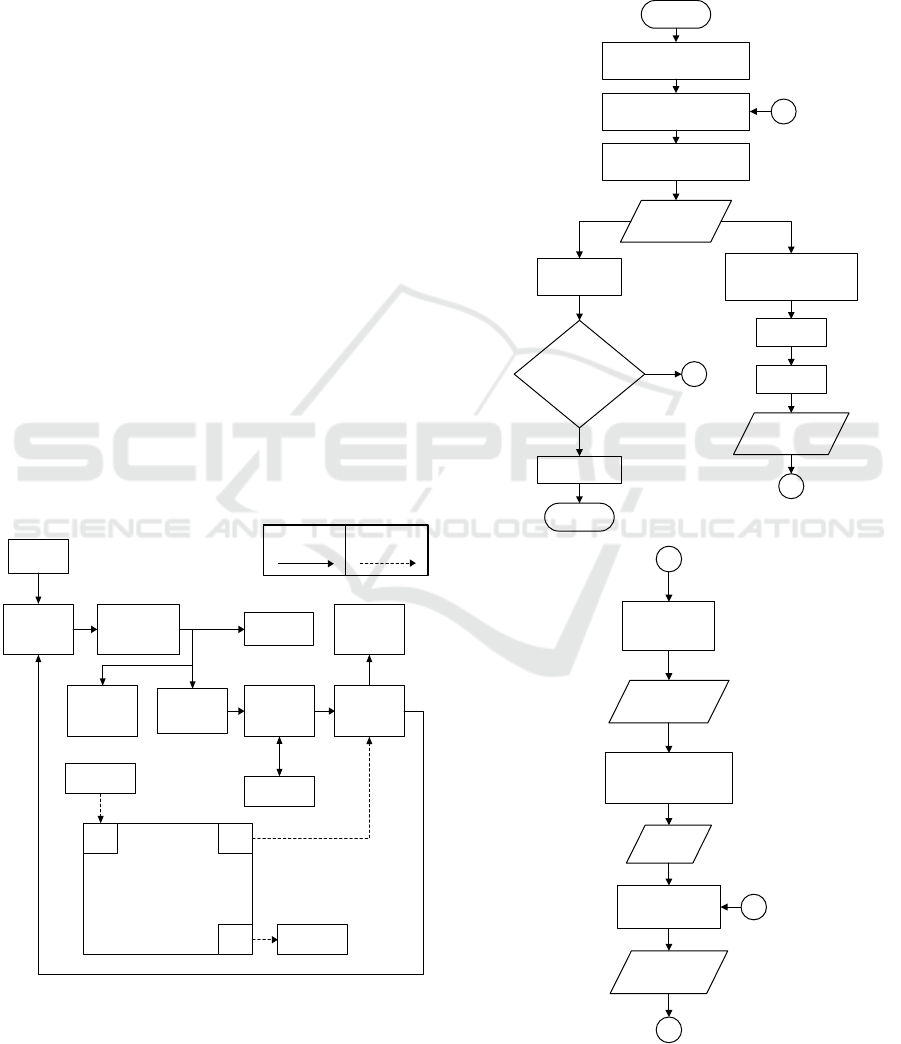
2.4 System Design
The overall system is depicted in Figure 2. The prime
mover used to rotate the synchronous generator in this
study was obtained from an electric drill set at a
rotational speed of 1000 rpm – 1300 rpm.
DC Power
Supply 12V 5A
Arduino Uno
LCD 16x2
Buck-Boost
Converter
Synchronous
Generator
Battery Charger
Controller
Battery
Load
DC Volt-
Ampere Meter
AC Voltmeter
Step-up
Transformator
Prime Mover
ADC
Potensiometer
PWM
GPIO
Power Line Control Line
Figure 2: The Experimental Setup and The Design Diagram
Block.
The rotational speed of this prime mover is made
stable so that the research discussion does not get out
of topic. The stable AC output voltage in this study
was generated from a step-up transformer with the
aim of getting a working voltage value of 110V AC.
Meanwhile, the synchronous generator used is a car
alternator that has a working voltage of 12V AC.
Start
Prime Mover
Synchronous Generator C
Lamp is
Brighter
DC Power Supply 12 Volt
5A
Charging
A
110 AC
Voltage
Is the Output Voltage
110 VAC ?
Adding Load
Yes
No
End
B
Battery
Step-up Transformator
DC Voltage
Turn
Potensiometer
Processing Data on
Arduino
A
ADC Value
PWM
Signal
Exciter (Buck-Boost
Converter)
B
C
Voltage
Excitation
Figure 3: Flow Chart Excitation System.
iCAST-ES 2021 - International Conference on Applied Science and Technology on Engineering Science
88
The output voltage of this transformer will then be
used as a supply for the excitation and loading
system. The electrical load used for testing the
stability of the output voltage is a 5-watt incandescent
lamp. In accordance with the block diagram in Figure
2, the excitation system used is a self-excited
excitation system. The self-excited system in this
study was designed by changing the AC voltage
output to a stable DC voltage with the aim of
supplying the battery storage system which is used as
an excitation supply. The use of the battery here is
done with the aim of making the supply input voltage
to the exciter, namely the buck-boost converter,
stable. The buck-boost converter exciter is controlled
by a microcontroller with ADC input from a
potentiometer to adjust the duty cycle of the exciter.
This stability setting is seen from the results of the AC
voltmeter reading which then by looking at the
voltmeter it can be done by setting the excitation by
turning the potentiometer. 16 x 2 LCD is used to
display the duty cycle value. The workflow of the tool
in this study can be seen in Figure 3 below.
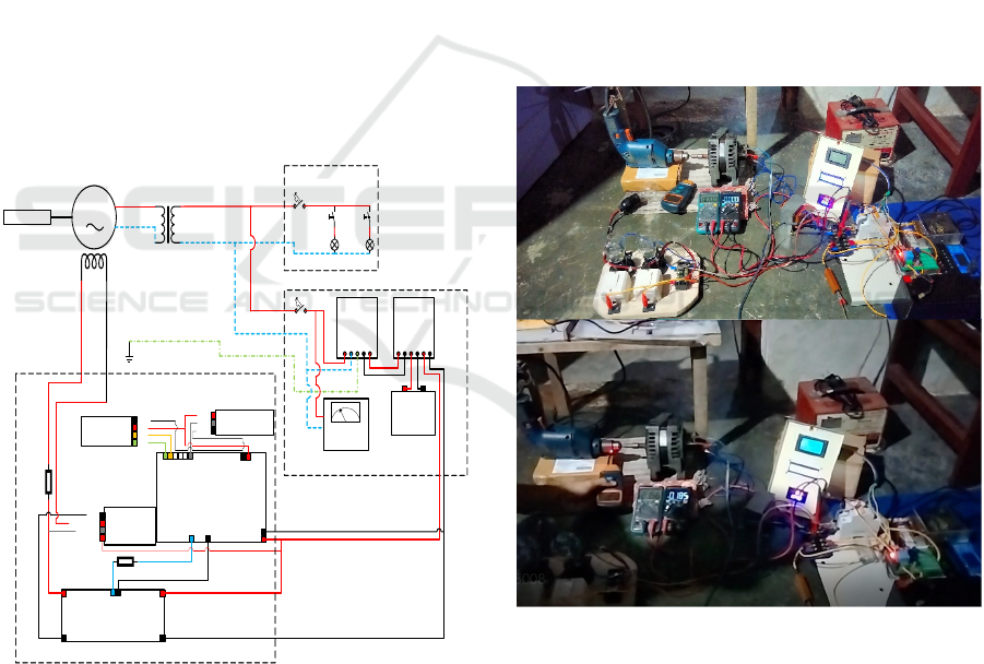
2.5 Wiring Diagram
G
F1 F2
L
N
0 – 12 V AC
0 – 110 V AC
L
N
PE
MCB 2 A
Lamp1
S1
MCB 6 A
Lamp2
S2
DC Power
Supply 12 V
5A
L N PE - +
Battery
Char ger
Cont ro ll er
+ - + - + -
Battery
AC
Voltmeter
Potensiometer
LCD 16x2
Vin
GND
GND
+5V
ARDUINO UNO
A0
A1
A2
A3
A4(S DA)
A5(S CL)
+5V
GND
SDA
SC L
+5V
GND
OUT
D6 PW M
BUCK-BOOST CONVERTER
Input +
Input -
Output +
Output -
PW M
Arduino
R2 20Ω
DC Volt-
Ampere Meter
Read Ampe re
GND
Re ad Volt
Vin
R1 1KΩ
GND
PWM
GND
Load System
Storage System
Control System
Prime Mover
Figure 4: Wiring Diagram of the Voltage Stabilizer.
The wiring diagram of the excitation system in this
study is shown in Figure 4. The excitation system
made has 2 systems with their respective functions
connected to each other. The two systems are storage
systems and control systems. The storage system is
used for charging the battery as an exciter supply in
the control system. The DC voltage output from the
battery will be connected to the supply with the
exciter (buck-boost converter) and at the same time
supply to the microcontroller (Arduino Uno).
The control system in the plan made uses Arduino
Uno as a regulator of the exciter output voltage value
(buck-boost converter). The excitation DC output
voltage on the exciter is controlled by setting the duty
cycle by the microcontroller with the ADC input by
the potentiometer. The DAC output value from the
microcontroller in the form of PWM is obtained from
the conversion of the potentiometer ADC value to the
duty cycle value.
3 RESULTS
In accordance with the purpose of this study, the tests
carried out were testing the synchronous generator
excitation system with no load and electrical load.
Figure 5 shows the testing of the excitation system
circuit in this study.
Figure 5: Excitation System Circuit Testing.
Excitation system testing is carried out by keeping
the AC output voltage value reaching a working
voltage of 110V AC. Table 1 contains test data on the
effect of excitation current on AC output voltage
without loading.
Experimental Study of the Effect of Excitation Current on the Output Voltage of a Self-excited Synchronous Generator
89
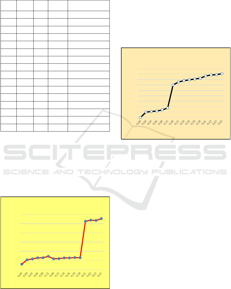
Table 1: Zero Load Test with If Setting.
RPM Vf
(V)
If
(A)
V Out
(V)
K (%)
1159 0,00 0,00 11,76 No Excitation
1194 2,00 0,04 21,14 99
1120 2,20 0,05 23,17 90
1297 2,40 0,06 25,60 80
1280 2,80 0,08 25,84 70
1196 3,50 0,12 28,82 60
1059 12,00 0,48 23,48 50
1005 13,10 0,53 23,83 40
1130 13,60 0,54 25,41 30
1114 13,90 0,56 25,40 20
1113 14,20 0,58 26,18 10
1110 14,50 0,58 25,82 0
1275 15,30 0,61 105,20 52
1268 15,70 0,62 107,80 51
1233 15,80 0,63 107,10 50
1291 16,20 0,65 111,10 49
This no-load test was carried out at Alwy's house
which aims to see how the effect of the excitation
current on the AC output voltage. In this no-load test,
the rpm value is maintained in the range between
1000 - 1300 rpm, because the prime mover used is an
electric drill with rpm depending on the stability of
the electric voltage at home. Based on the data in
Table 1, the output voltage will be strongly influenced
by the presence of excitation current according to the
graph in Figure 6 below.
Figure 6: Characteristics of Excitation Current Change to
The Zero Load Generator Output Voltage.
The graph in Figure 6 shows that the output
voltage will increase with an increase in excitation
current. The increase in excitation current will cause
the rotating magnetic field to increase in the rotor.
The rotating field generated by this rotor will then be
induced in the armature coil in the stator which results
in greater magnetic flux. The greater the magnetic
flux changes, the greater the induced emf at the ends
of the coil.
Figure 7: Graph Effect of The Excitation Voltage on The
Excitation Current.
Figure 7 shows an increase in excitation current
caused by an increase in excitation voltage in the
exciter with the duty cycle setting as switching on the
buck-boost converter MOSFET which is regulated by
the microcontroller (Permana & Dewira, n.d.). The
buck-boost converter which acts as an exciter will
provide a DC voltage to generate an excitation current
which makes the field coil on the generator rotor
create a magnetic field. So that in this study attempts
to adjust the value of the excitation current by setting
the excitation voltage because the value of the
excitation resistance is fixed.
The reliability of the generator in producing
electrical energy is also seen from testing the stability
of the output voltage against loading. Figure 8 is a
photo of the excitation system testing with a load
using a 5watt incandescent lamp.
The following table 2 contains the test data for the
excitation system under loading if the excitation
current value is kept constant. The electrical load used
is a 5watt incandescent lamp. This incandescent lamp
is used as an electrical load because it has a good cos
phi compared to other electrical loads.
0,00
20,00
40,00
60,00
80,00
100,00
120,00
V Out (V)
If (A)
If Against V Out
0,00
2,00
4,00
6,00
8,00
10,00
12,00
14,00
16,00
18,00
Vf (V)
If (A)
Vf Against If
iCAST-ES 2021 - International Conference on Applied Science and Technology on Engineering Science
90
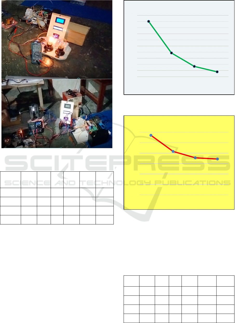
Figure 8: Excitation System Circuit Testing with Lamp.
Table 2: Loaded Test with Constant If.
RPM
Vf
(V)
If
(A)
K
(%)
Ia
(A)
V
Out
(V)
Load
(Watt)
1142,00 14,30 0,59 0 0 90,17 0
832,90 14,30 0,59 0 0,124 38,65 1 x 5
710,40 14,30 0,59 0 0,191 16,71 2 x 5
687,50 14,30 0,59 0 0,224 7,86 3 x 5
The value of the excitation current is kept constant
in order to see the effect of increasing the value of the
load current (Ia) on the value of the resulting output
voltage. The graph in Figure 9 describes the
characteristics of the change in load current (Ia) to the
output voltage.
Characteristics of changes in the value of the load
current (Ia) which is increasing will cause the value
of the output voltage to decrease. In addition, the
increasing value of the load current will cause the
value of the RPM to decrease. The graph in Figure 10
shows a decrease in RPM caused by an increase in
load current.
Figure 9: Load Change Characteristics (Ia) to The
Generator Output Voltage with Constant If.
Figure 10: The Effect of Increasing Load Current on RPM.
Table 3 below contains data from the experimental
results of the excitation system under load conditions
by setting the excitation current value. This experiment
was conducted with the aim of knowing the effect of
increasing the excitation current under load conditions
on the resulting output voltage.
Table 3: Loaded Test with If Setting.
RPM
Vf
(
V
)
If
(
A
)
K
(
%
)
Ia
(
A
)
V Out
(
V
)
Load
(
Watt
)
1175 16,3 0,66 50 0,000 110,40 0
1172 20,6 0,84 46 0,146 95,40 1 x 5
1178 24,7 1,06 36 0,250 90,90 2 x 5
1172 28,9 1,30 0 0,318 89,80 3 x 5
0
10
20
30
40
50
60
70
80
90
100
0 0,124 0,191 0,224
V Out (V)
Ia (A)
Ia Against V Out
0
200
400
600
800
1000
1200
0 0,124 0,191 0,224
RPM
Ia (A)
Ia Against RPM
Experimental Study of the Effect of Excitation Current on the Output Voltage of a Self-excited Synchronous Generator
91

The graph in Figure 11 shows the effect of the
excitation current (If) on the output voltage under
load conditions.
Figure 11: Effect of The Excitation Current on The Output
Voltage in Loaded Condition.
From the graph, the value of the output voltage
will be relatively stable at the condition of the output
voltage value of 80 – 110 V AC when the load current
value increases. This stable output voltage is because
the value of the excitation current is increased
according to the condition of adding a load that causes
the output voltage to drop.
Figure 12: Graph Effect of The Excitation Voltage on The
Excitation Current with Load Changing Condition.
Under loaded conditions, the excitation current
value will give a stable output voltage value. An
increase in the excitation current in this study is
caused by an increase in the value of the excitation
voltage at the exciter. The graph in Figure 12 shows
the condition of an increase in excitation current
caused by an increase in excitation voltage.
4 DISCUSSIONS
Each test performed, the rotation of the synchronous
generator is treated constant ranging from 1000 -
1300 rpm, and it is seen that the increase in the value
of the excitation current in the field winding greatly
affects the generator output voltage. The greater the
excitation is given, the greater the generator output
will be (Boldea, 2016). Excitation current test results
are in line with the following equation:
𝐸𝑓𝑓 𝑛 𝑐 ∅
(1
)
Where:
Eff = ggl effective induced (Volt)
c = constant
n = rotor rotation (rpm)
∅ = magnetic flux (Weber)
If the excitation current value (If) is constant when
the load test is carried out, the voltage value will be
inversely proportional to the addition of the load
current (Ia) (Li, 2019). The higher the load current
value, the lower the output voltage value. The value
of the voltage can be stabilized by increasing the
excitation current in the field coil in the rotor of the
synchronous generator.
5 CONCLUSIONS
Based on the tests and analyzes that have been carried
out, it can be concluded that the output voltage of the
synchronous generator is strongly influenced by the
adjustment of the excitation current given. The output
voltage value of 110 VAC in the zero-load test occurs
when the excitation current is 0.65A while if an
excitation current of 0.04 the output voltage is still at
a value of 21.14 VAC. The generator output voltage
will be directly proportional to the excitation current
value. The addition of the load causes the generator
output voltage to decrease, this shows an inverse
relationship between the addition of the load current
(Ia) and the synchronous generator output voltage.
REFERENCES
Badan Pengkajian dan Penerapan Energi. (2018). Outlook
Energi Indonesia 2018: Energi Berkelanjutan untuk
Transportasi Darat Book. In Badan Pengkajian dan
Penerapan Energi (BPPT) (Issue September).
Baskoro, M. B., & Adiwibowo, P. H. (2017). Uji
Eksperimental Pengaruh Sudut Basin Cone Terhadap
0
20
40
60
80
100
120
0,66 0,84 1,06 1,3
V Out (V)
If (A)
If Against V Out
0
5
10
15
20
25
30
35
0,66 0,84 1,06 1,3
Vf (V)
If (A)
Vf Against If
iCAST-ES 2021 - International Conference on Applied Science and Technology on Engineering Science
92

Kinerja Turbin Reaksi Aliran Vortex. Jurnal Teknik
Mesin, 05(02), 81–91.
Boldea, I. (2016). The Electric Generators Handbook,
Synchronous Generators, Second Edition (CRC Press).
Fahmi, M. S., & Irwanto. (2020). SUPPLAY EKSITASI
Output Generator 300 Mw Menggunakan Metode Pola
Titik Daya Reaktif. Journal of Mechanical Engineering
and Mechatronics, 5(1), 11–20.
Li, J. (2019). Design and Application of Modern
Synchronous Generator Excitation Systems. Tsinghua
University.
Nugraha, Anggara Trisna, and Dadang Priyambodo.
"Prototype Hybrid Power Plant of Solar Panel and
Vertical Wind Turbine as a Provider of Alternative
Electrical Energy at Kenjeran Beach Surabaya."
Journal of Electronics, Electromedical Engineering,
and Medical Informatics 2.3 (2020): 108-113.
Nugraha, Anggara Trisna, and Dadang Priyambodo.
"Design of Hybrid Portable Underwater Turbine Hydro
and Solar Energy Power Plants: Innovation to Use
Underwater and Solar Current as Alternative Electricity
in Dusun Dongol Sidoarjo." Journal of Electronics,
Electromedical Engineering, and Medical Informatics
3.2 (2021): 93-98.
Nurdin, A., Azis, A., & Rozal, R. A. (2018). Peranan
Automatic Voltage Regulator Sebagai Pengendali
Tegangan Generator Sinkron. Jurnal Ampere, 3(1),
163–173. ttps://doi.org/10.31851/ampere.v3i1.2144
Pambudi, Y. D. S., Rokhmanila, S., & Septian, A. (2020).
Rancang Bangun Generator Magnet Permanen Dan
Generator Induksi Pada Sistem Pltmh. Epic (Journal of
Electrical Power, Instrumentation and Control), 3(1),
45–51. https://doi.org/10.32493/epic.v3i1.3728
Priyambodo, Dadang, and Anggara Trisna Nugraha.
"Design and Build A Photovoltaic and Vertical
Savonious Turbine Power Plant as an Alternative
Power Supply to Help Save Energy in Skyscrapers."
Journal of Electronics, Electromedical Engineering,
and Medical Informatics 3.1 (2021): 57-63.
Permana, S. I., & Dewira, R. F. (n.d.). Pembuatan Kontrol
Arus Eksitasi Pada Modul Automatic Voltage
Regulator Dengan Menggunakan Mikrokontroler. 1–4.
Syahputra, R. (2012). Pengaruh Perubahan Arus Eksitasi
Terhadap Tegangan Keluaran Generator Sinkron.
Jurnal Teknologi, 12(2), 85–88.
Tampubolon, A. P., & Adiatama, J. C. (2019). Laporan
Status Energi Bersih Indonesia. 1–28.
Tim Sekretaris Jenderal Dewan Energi Nasional. (2019).
Indonesia Energy Out Look 2019. Journal of Chemical
Information and Modeling, 53(9), 1689–1699.
Experimental Study of the Effect of Excitation Current on the Output Voltage of a Self-excited Synchronous Generator
93
