
Wireless Power Transmitter Apparatus for Low-Voltage DC Power
Transmission Applications
C. Bambang Dwi Kuncoro
1a
, Arvanida Feizal Permana
1
and Cornelia Adristi
2
1
Department of Refrigeration, Air Conditioning and Energy Engineering, National Chin-Yi University of Technology,
No. 57, Sec.2, Zhongshan Rd., Taiping Dist., Taichung City 41170, Taiwan
2
Department of Electrical Engineering, Faculty of Engineering, Universitas Indonesia,
Jalan. Kampus UI, Kukusan, Beji, Depok 16424, Indonesia
Keywords: Wireless Power, Low-Voltage, Magnetic Induction, Interoperability, Transmitter.
Abstract: Wireless power transfer (WPT) technology and applications have become popular in recent years. This is a
re-emerging technology that allows a convenient, simple, easy use of electrical energy delivery from a power
source to an electrical load within a medium distance in the absence of any electrical cord. This paper presents
a wireless power transmitter apparatus that has the capability to propagate wirelessly a low voltage to a load
coupled at a wireless power receiver output module. The voltage to be transmitted coming from 2.5 ‒ 3.5 V
at a maximum current of 2A DC power source. It differs from typical developed wireless power transmission
systems which usually transmit high voltage from either DC or AC power sources. The proposed apparatus
was developed applying the magnetic induction concept, working at the operating frequency of 110kHz at a
maximum transmission distance of about 10mm. Maximum power transfer is achieved at 5W with 5V
constant output voltages and the maximum output current is up to 1.4A. These specifications are suitable for
electronic device power charger applications. The experimental results show the developed apparatus has a
peak power transfer efficiency of around 70% and complies with the international standard requirement for
interoperability.
1 INTRODUCTION
Over years ago, wireless power transfer systems have
been developed by adopting electromagnetic
concepts either mutual induction or resonance
methods. Nowadays, this technology is re-emerging
and appealing to researchers and developers applying
it in many applications from electronic devices to
electrical vehicle systems.
The WPT systems enable an electrical load to
obtain electrical energy that propagates wirelessly
from energy sources over a distance (Costanzo et al.,
2014, Garnica et al., 2013). This concept confirmed
by Heinrich Hertz experiment in 1888
(wikipedia.org). His results were proof
experimentally the existence of electromagnetic
radiation for the first time. He used parabolic reflector
and induction coil to emit high-frequency electric
power generated by an oscillator over a tiny air gap.
Over years, this system has improved the overall
a
https://orcid.org/0000-0002-5054-2794
system efficiency, therefore various applications
adopted this technology to offer the user more
convenience and better experience.
Comparing with the conventional plug-in charger,
WPT offers a more compatible and attractive
alternative because it can recharge all electricity
operated devices using a single power source within
an average–sized room. Moreover, the contactless
feature of WPT also raises their freely and easily to
move, and reliability with low cost as it uses minimal
of insulation material and wire for the cables (Barman
et al., 2015). This technology has a prospect to be a
standard for wireless power transmission. The first
industry standard for mobile devices inductive
charging released by the Wireless Power Consortium
(WPC) (Johns, 2011), which is called “Qi”
(pronounce “chee”) (WPC, 2011).
In the literature, several wireless power transfer
works based on inductive electromagnetic coupling
have been developed and realized. In (Cao et al.,
Kuncoro, C., Permana, A. and Adristi, C.
Wireless Power Transmitter Apparatus for Low-Voltage DC Power Transmission Applications.
DOI: 10.5220/0010939500003260
In Proceedings of the 4th International Conference on Applied Science and Technology on Engineering Science (iCAST-ES 2021), pages 33-40
ISBN: 978-989-758-615-6; ISSN: 2975-8246
Copyright
c
2023 by SCITEPRESS – Science and Technology Publications, Lda. Under CC license (CC BY-NC-ND 4.0)
33

2014), the authors presented WPT system for portable
electronic device. The system is composed of
transmitter (Tx) and receiver (Rx) modules, and has
power efficiency of 65%. Tx and Rx coils were
developed using Fe-based soft magnetic composites
sheet to improve power transfer efficiency. The Tx
module is powered by 20V, 20W DC to provide more
than 5W at output power of Rx module.
A 36W WPT system for LED lighting
applications is presented by Chen et al. (Chen et al.,
2013). The Tx module powered with 34V DC to
provide 35.9W across a 30Ω load at Rx output
module. It has 82% power delivery efficiency with
the distance range of 5mm. A class E amplifier was
applied in Tx module.
Her et al. developed a WPT system that involve
the green energy concept. PIC16F1937
microcontroller was applied on Tx module to
generate 125kHz PWM (Her et al., 2012). The
developed system is used to charge a PRC Li-
Polymer 360mAh battery with power delivery
efficiency of 43.4%. Tx module is powered by 8V,
320mA DC to achieve output power of 3.73V,
298mA at Rx output module.
On chip Tx module for WPT system that comply
with Qi standard specification is presented by Berger
et al. (Berger et al., 2016). The module was proposed
to maximize the power efficiency. It is developed to
provide maximum output power at 5W for 3.3V
battery charger application. The developed chip is
characterized by three kind of peak receiver
efficiencies; 72% for passive mode rectifier control at
an output power of 1.4W, 82% for semi-active mode
rectifier control at an output power of 1.4W, and 88%
for fully active mode rectifier control at an output
power of 1.4W.
A full-bridge resonant inverter for WPT system is
presented by Galizzi et al. (Galizzi et al., 2013). The
bridge is coupled with Tx part and has various supply
in range of 2 ‒ 3 V to control total power transfer. It
has a peak efficiency of 70% and work with certified
WPT standard such as Qi standard.
Nataraj et al. present a DC‒DC WPTs simulation
model (Nataraj et al., 2017). The model was
developed using Multisim. The simulation worked
with the operating frequency range of 10Hz to 1kHz
and an Tx input signal of 5V DC. Their simulation
shows the output voltage is increased proportionally
with the load resistance.
A wireless powered sensor chip is introduced by
Yoo et al. (Yoo et al., 2010). The sensor consumes
12uW that is harvested energy surrounding using a
health monitoring chest band with 54.9% efficiency.
It works based on inductive coupling of WPT and an
Adaptive Threshold Rectifier (ATR).
A wireless power receiver with dual mode
transmission methods is presented by authors by
Satyamoorthy at el. (Satyamoorthy at el., 2014). The
receiver works in the 110 to 205 kHz (inductive
mode) and 6.78MHz (resonance mode) frequency
bands. It provides 5W output to comply with Qi
standard and achieves a peak efficiency at 84% in
inductive mode and 82% in resonant mode.
As mention in the literature above, some WPT
systems based on magnetic induction have been
developed for various applications. Some methods
also presented in order to improve and revise the
performance and functionality. In a couple of recent
years, many applications begin to change over to
WPT technology in order to transmit the power
because of some benefits offered this technology.
Although many WPT applications have been
developed, however, in some application cases, a low
voltage from DC power source needs to be transferred
wirelessly to the load, but the load needs a voltage
higher than the voltage provided by the power source.
This paper presents a wireless power transfer
apparatus which capable to transmit a low DC voltage
wirelessly to an electrical load that couples with
wireless receiver module. The voltage to be
transmitted coming from 2.5 ‒ 3.5 V at a maximum
current of 2A DC power source. Then, the receiver
can provide a stable output voltage at 5V and a
maximum current up to 1.4A. The developed
apparatus complies with the international standard
requirement for interoperability. The proposed
apparatus also differs from typical developed wireless
power transmission systems which usually transmit
high voltage from either DC or AC power source.
Some WPT applications in medical implantable also
supply a low voltage to be transmitted to the load but
the load also consumes voltage almost same as the
voltage transmitted by the transmitter.
2 MATERIALS AND METHODS
2.1 Basic Design Concept
The proposed apparatus is design based on
electromagnetic induction principle. The concept is
described in Maxwell’s equations is composed of
Ampere's circuital and Faraday's induction laws (Ban
et al., 2013). Ampere's circuital law introduces the
relation between magnetic fields and the electric
current, while the Kelvin-Stokes theorem is
iCAST-ES 2021 - International Conference on Applied Science and Technology on Engineering Science
34

equivalent to Ampere's circuital law and written in
either integral form or differential form. Ampere's
circuital law is a line integral of magnetic field around
an arbitrary closed curve c. The electric current passes
through a surface s which in turn bounded and
enclosed by curve c. The total current i passes through
the surface s enclosed by c is proportional to the
magnetic B field around a closed curve c (Sadiku,
2015):
𝐁.d𝐥=µ
𝐉.d𝐬= µ
i
(1)
where µ
0
is the magnetic constant, and J is the free
current density.
Due to symmetry, the magnetic field lines
perform concentric circles in planes perpendicular to
the wire. The direction is the right-hand curl fingers
if the wire is wrapped by them with the thumb in
current direction. Suppose that the closed curve c is a
circle of radius r centered on straight wire. The
magnetic flux density can be expressed in line
integral as follow (Sadiku, 2015):
𝐁.d𝐥= 2πrB
= µ
𝑖
(2)
B=
µ
i
2πr
(3)
Actually, Faraday’s law describes the
phenomenon is called electromagnetic induction. An
electromotive force (emf) is induced in any closed
circuit using a time-varying magnetic flux through the
circuit. Faraday’s law of induction uses the magnetic
flux Ф through a hypothetical surface s whose
boundary is a wire loop l. The magnetic flux is
defined by a surface integral (Hayt et al., 2012):
Ф= 𝐁.d𝐬
𝒔
(4)
The induced emf ε is proportional to the rate of
change of the magnetic flux (Hayt et al., 2012):
ε= −
dФ
dt
(5)
Lenz’s law expresses the direction of the induced
current caused by the emf, which indicates that the
magnetic field produced by the induced current
opposes the original change in magnetic flux.
The magnetic field generated by one coil is
coupled with other coils. The first coil (coil
1
) has N
1
turns which carries a current i
1
and emits a magnetic
field vector B
1
. The magnetic field lines pass through
the coil
1
will then also pass through the coil
2
. The
magnetic flux through coil
2
due to i
1
is expressed by
Φ
21
. Thus, there will be an induced emf associated
with the changing magnetic flux in the second coil by
varying i
1
with time (Hayt et al., 2012):
𝜀
=−N
dФ
dt
=−
d
dt
𝐁
.d𝐀
(6)
2.2 Wireless Power Consortium (WPC)
Standard
There are three essential points which is defined by
the WPC regarding standard of inductive charging of
mobile devices; the power transmitter, the power
receiver, and the communications protocol between
the two devices (Wei et al., 2009). Low power for
wireless power transfer is defined transmitting the
power in the range of 0 to 5 W, and the distance
between the two coils typically is 5mm (Johns, 2011).
The power transmission uses two planar coils to emit
electric energy from the power transmitter to the
power receiver based on the inductive coupling
method.
The WPC was founded in 2009, and at least 80
international companies joined as members at that
time. The year the consortium was established the
first international standard on wireless power for
mobile devices of to 5W released. According the
wireless power consortium, the key low-frequency
specification for wireless power transmission is
(WPC, 2011):
• Architecture: magnetic induction
• Antenna structure: planar
• Coupling: tightly coupled
• Operating frequency: 110 – 205 kHz.
2.3 Proposed Design
The proposed WPT transmitter apparatus was
designed to transmit wirelessly 2.5‒3.5 V DC to an
electrical load that couples with a wireless receiver
module. The maximum current source is 2A provided
by a DC power source. In general, a WPT transmitter
apparatus is used to propagate high voltage from
either DC or AC power source to an electric load.
Therefore, the proposed apparatus differs from the
typical WPT application.
Wireless Power Transmitter Apparatus for Low-Voltage DC Power Transmission Applications
35
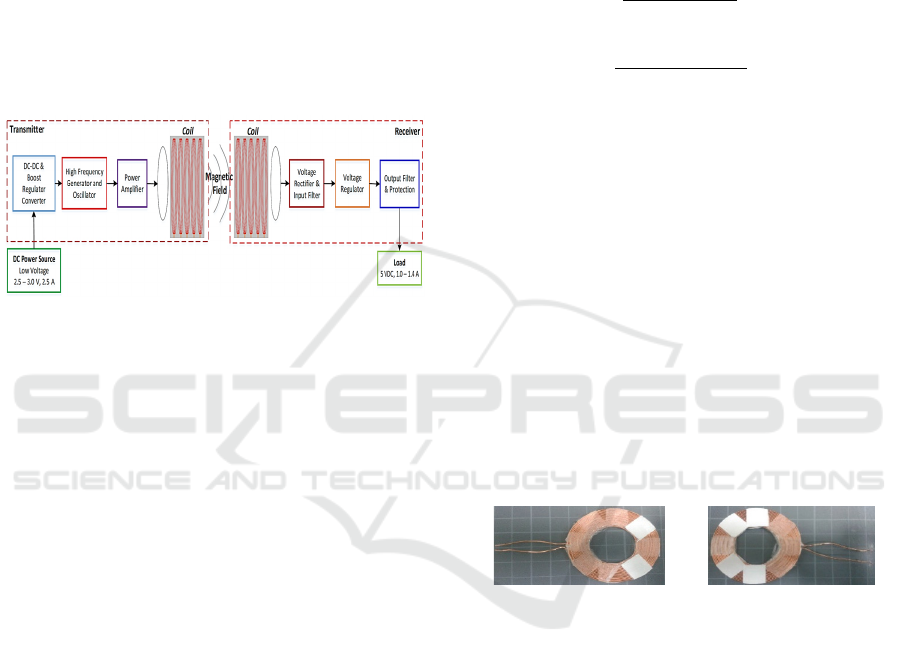
Overall, the proposed WPT system is shown in
Figure 1. It is composed of Tx apparatus (Figure 1(a))
and Rx apparatus (Figure 1(b)). The proposed WPT
system adopts an inductive coupling method and is
compatible with the standard wireless power
consortium. The proposed Tx apparatus was equipped
with a front-end DC‒DC and boost regulator
converter circuit. This circuit provides suitable
voltage for a frequency and oscillator circuit. A power
amplifier circuit is excited by a signal from the
frequency and oscillator circuit to generate a stable
high-power electromagnetic wave. Finally, this
electromagnetic wave is emitted by the Tx coil to the
Rx apparatus.
(a) (b)
Figure 1: Block diagram of the proposed apparatus:(a)
transmitter; (b) receiver.
A wireless Rx apparatus is also designed to
conduct a performance test of the proposed wireless
Tx apparatus. The wireless Rx apparatus main circuit
includes a rectifier, filter, and voltage regulator as
shown in Figure 1(b). It can provide a stable 5V
output voltage at a maximum output current of up to
1.4A.
3 DESIGN AND RESULTS
The apparatus prototype has been developed
according to the block diagram shown in Figure 1. It
consists of two parts; the coil and electronic circuitry.
3.1 Coil Design
In coil design of WPT system, the magnetic field is
essential because it has key role to create inductively
coupling between Tx and Rx modules. The magnetic
fields generate self-inductance of each coil and
mutual-inductance between the two coils. Several coil
parameters such as geometry, type and size of wire,
number of turns, self-inductance and mutual-
inductance are necessary to consider in coil design.
Those coil parameters can maximize coupling
coefficient between two coils.
The proposed apparatus utilizes a flat spiral air
core coil. It was chosen to maximize the Q-factor,
efficiency, power handling, and the related magnetic
field generated by the transmitter coil (Mitcheson et
al., 2004). The flat spiral air core coil self-inductance
can be described by Harold A. Wheeler’s
approximations formula (Mohan et al., 1999,
Wheeler, 1928):
L=
N
.A
30.A −11.D
(7)
A=
D
+N.(W+S)
2
(8)
where D
i
is the coil inner diameter (inch), W is wire
diameter (inch), N is the turn total number, S is the
turn spacing (inch) and L is the inductance
(microHenries (µH)).
Tx coil was designed having N= 17, number of
turns is 1, inner diameter (D
i
) is 25mm, turn spacing
(S) is 0mm, wire diameter (W) is 0.64mm, outer
diameter (D
o
) is 49.89mm and the wire length (Wl) is
191.97cm. The coil inductance is 13.9µH that was
calculated using Equations 7 and 8. Due to manual
manufacturing, Tx coil is characterized by 13.7µH of
inductance (L) and an outer diameter (D
o
) of
49.36mm. It was built using AWG22 wire that has
small diameter (0.64mm diameter and 0.0646mm
insulating layer) and can be used for carrying a
maximum current of 7A. Figure 2(a) shows Tx coil
geometry.
(a) (b)
Figure 2: Coil: (a) transmitter; (b) receiver.
Rx coil was characterized by 14.02µH of
inductance (L), an outer diameter (D
o
) of 49.50mm,
and 192.5cm in wire length (Wl). The coil parameter
and diameter were designed same as Tx coil to
maximize coupling efficiency. Figure 2(b) shows Rx
coil geometry.
3.2 Wireless Power Transmitter
Apparatus
Figure 3 shows the integrated Tx coil and wireless
power transmitter PCB (80 × 17 mm) prototype. Part
A is a DC‒DC and boost regulator converter was
applied using a high efficiency step up converter chip
(MT3608), input and output capacitor filters (22µF),
iCAST-ES 2021 - International Conference on Applied Science and Technology on Engineering Science
36
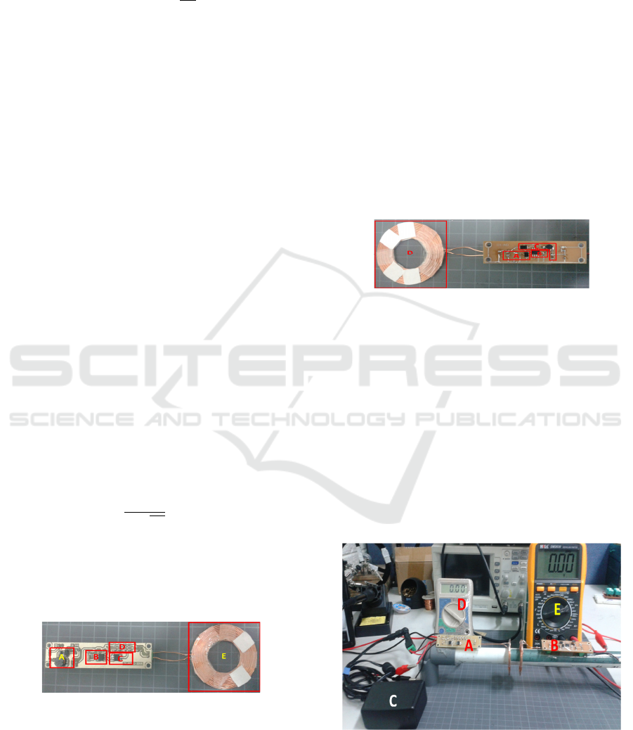
an inductor (22µH) to avoid saturation current, and a
diode (SS34) to limit peak current.
The output voltage is given by Equation (9):
V
= 𝑉
𝑥(1 +
R
R
)
(9)
where V
Ref
is the internal reference voltage in Volt,
R1 and R2 are the resistances in Ohm (Ω), and Vout
is the output voltage in Volt. Typical V
Ref
is 0.6V.
With R
1
=23,46kΩ (adjusting by potentiometer) and
R
2
=2.2kΩ, the boost regulator converter provides
output voltage of 7V at maximum current 2.5A from
input voltage source (Vs) of 2.5 ‒ 3.0 V.
A radio frequency power supply chip (XKT‒412),
resistors of 8.2kΩ and 47kΩ, and a capacitor of 1nF
built a high frequency generator (part B). Square
waves with frequency of around 70kHz was
generated by the radio chip. The signals have voltage
of 7V and a maximum current of 1A.
A power amplifier circuit (part C) was built by a
wireless power transmitter chip (T5336) and a
capacitor of 47µF/16V. This circuit generates
controllable high‒frequency power signal with
voltage gains of four times. Its output voltage is
around 32 Volts.
The operating frequency/oscillator (part D) was
controlled by the voltage difference between the DC
voltage and the T5336 output. The oscillator circuit
was built of LC tank, TX coil (13.9µH), and
capacitors bank of 39nF. The capacitor bank defines
the operating frequency of proposed TX of around
110kHz. This frequency complies with WPC standard
operation frequency between 100 – 205 kHz.
The operating frequency was obtained by
Equation (10):
f
=
1
2π
√
LC
(10)
where f is the oscillation frequency (Hertz (Hz)), L is
the coil inductance (Henry’s (H)), and C is the
capacitance (Farad (F)).
The circuitry and Tx coil built on PCB (80 × 20 mm).
Figure 3: Wireless power transmitter apparatus prototype.
3.3 Wireless Power Receiver Apparatus
The Rx coil (13.9µH) on wireless Rx apparatus will
absorb a high‒frequency oscillation wave from
wireless Tx apparatus. A voltage rectifier and input
filter circuit (part A) converts into a DC voltage. A
voltage rectifier was built by a capacitor of 27nF and
a diode of SS34. While input filter built by a capacitor
of 10µF/25V, and resistors of 10kΩ and 6.2kΩ.
The core of Rx apparatus (part B) is a wireless
power receiver chip (T3168) and voltage adjustment
(a voltage divider circuit composes of 6.2 kΩ and 2kΩ
resistors).
The output filter and protection (part C) was built
using a diode of SS34 and an inductor of 22µH
(feedback protection), and a capacitor of 10µF/16V
as an output filter.
The wireless Rx apparatus generates output
voltage at 5V and a maximum current up to 1.4A.
Figure 4 shows the integrated Rx coil and wireless
power receiver PCB (80 × 17 mm).
Figure 4: Wireless power receiver apparatus prototype.
4 EXPERIMENTAL AND
DISCUSSION
4.1 Experimental Method
The experiment was conducted to examine the
developed wireless Tx apparatus performance. The
experiment configuration is composed of a 2.5 ‒ 3.0 V,
2.5A DC power supply, wireless power Tx apparatus,
wireless power Rx apparatus, two multimeters, and an
Oscilloscope as shown in Figure 5.
Figure 5: Experimental setup. A is wireless power Tx
apparatus, B is wireless power Rx apparatus, C is DC power
source, D and E are multimeters.
Wireless Power Transmitter Apparatus for Low-Voltage DC Power Transmission Applications
37
The wireless power Tx and wireless power Rx
coils are configured at vertical alignment. The
wireless power Tx apparatus, which powered by DC
power supply, emitted power wirelessly to the
wireless power Rx apparatus coupled with either a
resistor or smartphone as an electric load.
Multimeters measure input power of wireless power
Tx apparatus and output power of the wireless power
Rx apparatus output. An Oscilloscope capture and
record the electromagnetic wave generated by
wireless power Tx apparatus.
The experiment will perform with configuration
of open load circuit, short circuit, and closed circuit
crossed the wireless power Rx apparatus output
terminal. A 4Ω resistor is used as an electric load. In
between range from 0 to 2 cm, the gap between Tx
and Rx coils is changed by the 0.5cm step. The
current, voltage, and power crossed the wireless
power Tx apparatus input terminal and the wireless
power Rx apparatus output terminal were measured
respectively. Moreover, the power delivery efficiency
also obtained using input/output power measurement
results.
The experimental also conducted to evaluate the
developed wireless power transmitter apparatus
compliance with the standard. A standard wireless
receiver charger module which couples with a
smartphone and a smartphone with standard wireless
receiver charger module built-in are used to perform
this experiment
4.2 The Characteristic Performance
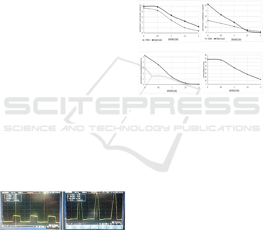
The generated waveform by the radio frequency
power supply chip (XKT-412) and the wireless power
transmitter chip (T5336) conjunction with an
Oscillator part are shown in Figure 6. The recorded
operating frequency is around 110kHz.
(
a
)
(
b
)
Figure 6: Generated waveforms; (a) the radio frequency
power supply chip waveform; (b) operating frequency
waveform.
Figure 6(a) shows 7V square waves with frequency
of about 68kHz generated by radio frequency power
supply chip (XKT‒412). XKT‒412 chip input
voltage is a step-up output power of the DC‒DC and
boost regulator converter (MT3608) part. This power
is a suitable input power driving for XKT‒412 chip
to generate a square wave signal for the wireless
power transmitter chip (T5336). Figure 6(b) shows
T5336 chip and oscillator wave output. The
waveform is a sinusoidal wave with an amplitude of
32 Volt and the frequency (operating frequency) of
about 110kHz. This operating frequency compliance
with the WPC standard.
Figure 7 shows the developed wireless power
apparatus performance characteristic.
(a) (b)
(c) (d)
Figure 7: The developed wireless power characteristics; (a)
the output voltage characteristic; (b) the output current
characteristic; (c) the output power characteristic; (d) the
efficiency characteristic.
The experiment result revealed that maximum output
voltage, current and power on the wireless power
receiver output are obtained at the smallest distance
(tightly coupled) between Tx and Rx coils whatever
the load configuration (open circuit, short circuit,
4Ω). Those will be decreased gradually with the
increase in the distance between the Tx and Rx coils
because of the high transmission coupling loss as
shown in Figures 7(a), 7(b) and 7(c).
The output power was measured at the wireless
power receiver output terminal crossed a resistor of
4Ω as shown in Figure 7(c). The power chart shows
the peak efficiency is around 70% which is obtained
at the maximum power delivery of 5.2W as shown in
Figures 7(d) and 7(c).
4.3 Battery Charging Testing
This experiment goal is to evaluate the developed
WPT apparatus compliance with the WPC standard.
Figure 8 (A is device under charge, B is wireless
power Tx apparatus, C is wireless power Rx
iCAST-ES 2021 - International Conference on Applied Science and Technology on Engineering Science
38
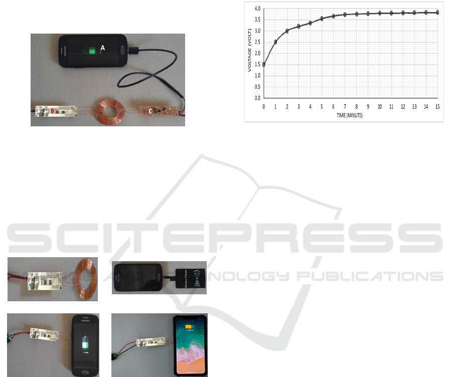
apparatus) shows the developed WPT apparatus
charged a smartphone battery (3.8V Li‒ion battery
5.7Wh). A 2.5‒3.0 V, 2.5A DC power supply was
connected to the developed wireless power Tx
apparatus, and the developed wireless power Rx
apparatus was coupled with the device under charge
(smartphone). This experiment result shows the
device under charge can be charged with suitable
power.
Figure 8: The battery charging experiment setup first
configuration.
Figure 9 shows other battery charging experiments.
The developed wireless power Tx apparatus (Figure
9(a)) was connected with a 2.5‒3.0 V, 2.5A DC
power supply. A smartphone couples with WPC
standard wireless Rx charger module (Figure 9(b))
was charged by the developed wireless power Tx
apparatus as shown in Figure 9(c).
(a) (b)
(c) (d)
Figure 9: The battery charging experiment setup second
configuration: (a) developed Tx module; (b) cell phone
couple with standard wireless Rx charger; (c) charging
process with standard wireless Rx charger; (d) charging
process with built-in standard wireless Rx module.
While Figure 9(d) shows the developed wireless
power Tx apparatus charged a smartphone with built-
in wireless power Rx module. The experiment results
show the developed wireless power Tx apparatus
works properly and it complies with WPC standard.
The charging performance test of the developed
apparatus was conducted using a 3.8V, 5.7Wh Li-ion
rechargeable battery. The charging voltage of the
battery under test is shown in Figure 10. In 15
minutes, the battery under test voltage reached a
maximum and the charging test was stopped due to
the battery voltage remained constant. Actually, the
charging process can be remained to achieve
maximum battery power capacity.
Figure 10: The Typical Charging Curve using the
Developed Apparatus.
5 CONCLUSIONS
The WPT design provides high design freedom in
achieving interoperability. In this research, a wireless
power transmitter apparatus prototype was developed
and implemented based on the magnetic inductive
coupling and complies with WPC standard. There are
various electrical dependent devices on the market
and specific applications have the potential to use this
apparatus.
According to the experimental results, the
developed wireless power transmitter apparatus can
work to meet the interoperability of various
applications that comply with international standard
either commercially or functionally. Its operating
frequency is 110kHz with a maximum transmission
distance of about 10mm. It achieves maximum power
transfer at 5W with voltage to be transmitted coming
from 2.5 ‒ 3.5 V at a maximum current of 2.0A DC
power source. From an efficiency point of view, it has
a peak power transfer efficiency of around 70%.
The coil design needs more attention in the design
process to improve the power transfer efficiency.
ACKNOWLEDGEMENTS
The authors thank the Ministry of Science and
Technology of Taiwan for the funding support with
grant number of MOST 110-2222-E-167-003-MY3.
Wireless Power Transmitter Apparatus for Low-Voltage DC Power Transmission Applications
39

REFERENCES
Costanzo, A., Dionigi, M., Masotti, D., Mongiardo, M.,
Monti, G., Tarricone, L., & Sorrentino, R. (2014).
Electromagnetic energy harvesting and wireless power
transmission: A unified approach. Proceedings of the
IEEE, 102(11), 1692–1711. https://doi.org/10.1109/
JPROC.2014.2355261.
Garnica, J., Chinga, R. A., & Lin, J. (2013). Wireless power
transmission: From far field to near field. Proceedings
of the IEEE, 101(6), 1321–1331. https://doi.org/
10.1109/JPROC.2013.2251411.
(March 12
th
, 2021,). www.wikipedia.org.
Barman, S. D., Reza, A. W., Kumar, N., Karim, Md. E., &
Munir, A. B. (2015). Wireless powering by magnetic
resonant coupling: Recent trends in wireless power
transfer system and its applications. Renewable and
Sustainable Energy Reviews, 51, 1525–1552.
https://doi.org/10.1016/j.rser.2015.07.031.
Johns, B. (April 5
th
, 2021). An Introduction to the Wireless
Power Consortium standard and TI ’ s compliant
solutions, Analog Applications Journal (1Q 2011).
www.ti.com/2q14-slyt401.
System Description Wireless Power Transfer, Volume I:
Low Power, Part 1: Interface Definition, Version 1.0.2.
(2011). Wireless Power Consortium (WPC).
Cao, G., Kim, H.-J., Choi, D., Lim, J., Cheng, P., & Bae, S.
(2014). Design of a wireless power transmission system
for portable electronic equipment. 2014 17th
International Conference on Electrical Machines and
Systems (ICEMS), 1935–1938. https://doi.org/10.
1109/ICEMS.2014.7013800.
Chen, W.T., Chinga, R.A., Yoshida, S., Lin, J., Hsu, C.K.
(2013). A 36 W Wireless Power Transfer System with
82% Efficiency for LED Lighting Applications,
Transactions of Japan Institute of Electronics
Packaging, 6(1), 32-37.
Her, M.L., Wu, P.H., Huang, W.Z., Wang, Y.L., Kung, S.H.
(2012). Design and Implementation of a Wireless
Power Transmission System with Green Energy
Concept, Cross Strait Quad-Regional Radio Science
and Wireless Technology Conference, 64-67.
Berger, A., Agostinelli, M., Sandner, C., Vesti, S., &
Huemer, M. (2016). High efficient integrated power
receiver for a Qi compliant Wireless Power Transfer
system. 2016 IEEE Wireless Power Transfer
Conference (WPTC), 1–4. https://doi.org/10.
1109/WPT.2016.7498862.
Galizzi, M., Caldara, M., Re, V., Vitali, A. (2013). A novel
Qi-standard compliant full-bridge wireless power
charger for low power devices, 2013 IEEE Wireless
Power Transfer (WPT), 44-47. https://doi.org/
10.1109/WPT.2013.6556877.
Nataraj, C., Khan, S., Eniola, F. F., & Selvaperumal, S. K.
(2017). Design of simple dc-to-dc wireless power
transfer via inductive coupling. 2017 Third
International Conference on Advances in Electrical,
Electronics, Information, Communication and Bio-
Informatics (AEEICB), 50–55. https://doi.org/10.1109/
AEEICB.2017.7972382.
Yoo, J., Yan, L., Lee, S., Kim, Y., & Yoo, H.-J. (2010). A
5. 2 mw self-configured wearable body sensor network
controller and a 12 $\mu$w wirelessly powered sensor
for a continuous health monitoring system. IEEE
Journal of Solid-State Circuits, 45(1), 178–188.
https://doi.org/10.1109/JSSC.2009.2034440.
Satyamoorthy, A., Riehl, P., Akram, H., Yen, Y.-C., Yang,
J.-C., Juan, B., Lee, C.-M., & Lin, F.-C. (2014).
Wireless power receiver for mobile devices supporting
inductive and resonant operating modes. 2014 IEEE
Wireless Power Transfer Conference, 52–55.
https://doi.org/10.1109/WPT.2014.6839626.
Ban, Y.-L., Chen, J.-H., Li, J. L.-W., & Hu, W. (2013).
Printed wideband notched antenna for wireless USB
dongle attached to laptop computer. Journal of
Electromagnetic Waves and Applications, 27(2), 257–
266. https://doi.org/10.1080/09205071.2013.743499.
Sadiku, M. N. O. (2015). Elements of electromagnetics
(Sixth edition). Oxford University Press.
Hayt, W. H., & Buck, J. A. (2012). Engineering
electromagnetics (8th ed). McGraw-Hill.
Wei, X. C., Li, E. P., Guan, Y. L., & Chong, Y. H. (2009).
Simulation and experimental comparison of different
coupling mechanisms for the wireless electricity
transfer. Journal of Electromagnetic Waves and
Applications, 23(7), 925–934. https://doi.org/10.1163/
156939309788355180.
Mitcheson, P. D., Green, T. C., Yeatman, E. M., & Holmes,
A. S. (2004). Architectures for vibration-driven
micropower generators. Journal of Micro-
electromechanical Systems, 13(3), 429–440.
https://doi.org/10.1109/JMEMS.2004.830151.
Mohan, S. S., del Mar Hershenson, M., Boyd, S. P., & Lee,
T. H. (1999). Simple accurate expressions for planar
spiral inductances. IEEE Journal of Solid-State
Circuits, 34(10), 1419–1424. https://doi.org/10.110
9/4.792620.
Wheeler, H. A. (1928). Simple inductance formulas for
radio coils. Proceedings of the IRE, 16(10), 1398–1400.
https://doi.org/10.1109/JRPROC.1928.221309.
iCAST-ES 2021 - International Conference on Applied Science and Technology on Engineering Science
40
