
The Effect of Condenser Cooling to Coefficient of Performance
(COP) and Electrical Consumption on AC Split
Ida Bagus Gde Widiantara
a
and I Wayan Suastawa
b
Politeknik Negeri Bali Kampus Bukit Jimbaran, Kuta Selatan Badung, Indonesia
Keywords: Modified Condenser, Coefficient of Performance (COP), Electrical Consumption, Condensed Water.
Abstract: The refrigeration equipment currently available is a split AC with some capacity. One of the processes that
occur in cooling machine is condensation which produces water and hot refrigerant. Inside the condenser,
some of refrigerant heat must be removed with the help of a blower to avoid the damage of compressor. Seeing
this, the condensed water from the evaporator will be reused as a cooling fluid. The purpose of this research
is to determine the coefficient of performance (COP) and electrical consumption without and using an
additional condenser cooling system. The test was carried out by modified condenser split AC 1 Pk R-410a
by installing 9 nozzles, a DC pump where the 3 nozzles horizontal and 3 nozzles vertical. The independent
variables of this test are the 3 nozzles horizontal position and the spraying time is 1, 2 and 3 minutes. The
room used is a 6 x 6 x 3.5 m as cooling load. From the results, it was found that there was an increase in the
performance of the cooling machine with the addition of a cooling system of about 34%, while in the electrical
consumption, there was a slight decrease about 5%.
1 INTRODUCTION
Indonesia as a tropical country that gets sunlight
almost all year round. This condition has an impact
on the air temperature and humidity which is quite
high. Along with the human desire to more comfort,
the use of cooling systems, air conditioning (AC) for
comfort is increasing. In its application, this system is
used in various aspects of life, ranging from the food
industry, chemical industry, hotels, hospitals,
aviation, shipping and even in households.
One type of cooling system that we often find is a
split cooling system where the evaporator will be
placed inside of the room but the compressor,
condenser and the expansion valve are outside which
are widely used in households. Generally air
conditioning generally work on the principle of vapor
compression, where there are several main
components, such us compressor, condenser,
expansion valve and evaporator. These 4 components
form a system to condition the air of a room. In the
process, there are two main processes i.e. heat transfer
processes, the process of absorption of heat in the
evaporator and heat dissipation in the condenser
a
https://orcid.org/0000-0001-7349-9146
b
https://orcid.org/0000-0001-9290-3298
where the heat in the refrigerant is pushed into the
environment using air and assisted by blower, where
the condensed water from the evaporator will be
discharged through the exhaust pipe. This process
will not take place perfectly when the outside air
temperature is high enough (Patel and Sheth 2015) so
that an additional system is needed to cool the
condenser and reduce compressor work. In direct
evaporative system, water evaporates directly in the
air stream, producing an adiabatic process of heat
exchange in which the air-dry bulb temperature
decreases as its humidity increases. Thus, the amount
of heat transferred from the air to the water is the
same as the one employed in the evaporation of the
water. (Porumb, Bălan, and Porumb 2016) said that
the evaporative system allowed the reduction of
energy consumption for the fresh air cooling with
almost 80% and also (Patel and Sheth 2015) mention
that the evaporative system is ecofriendly and is not
associated with ozone layer depletion problem
because it does not need any refrigerant. Seeing this,
the researcher wants to make an innovation, reducing
the use of electric power, but the comfort can still be
fulfilled.
Widiantara, I. and Suastawa, I.
The Effect of Condenser Cooling to Coefficient of Performance (COP) and Electrical Consumption on AC Split.
DOI: 10.5220/0010939300003260
In Proceedings of the 4th International Conference on Applied Science and Technology on Engineering Science (iCAST-ES 2021), pages 23-26
ISBN: 978-989-758-615-6; ISSN: 2975-8246
Copyright
c
2023 by SCITEPRESS – Science and Technology Publications, Lda. Under CC license (CC BY-NC-ND 4.0)
23
Data on electricity usage, especially in its use for
air conditioning, has increased quite sharply. The
Executive Director of the IEA (International Energy
Agency) was said in Asia, respectively ASEAN, that
the use of air conditioners had triggered a higher
global demand for electricity. (Alhamdo, Theeb, and
Abdulhameed 2015) also mention that in air cooled
condensers, the power consumption is a major issue
in vapor compression cycle. The power consumption
concern increased much more if the air-cooled
condensers work in area with very high ambient
temperature (between 50-60 ⁰C). Seeing these
phenomena, the researchers tried to further examine
the use of evaporative cooling systems in Air
Conditioning. From a previous study (Ridhuan and
Juniawan 2014) said that the highest coefisient of
performance (COP) value of cooling with only
blower (before modified) was 6.44 while the highest
COP after being modified with evaporative cooling
systems was 15.43. So it can be said that cooling with
water is better than air conditioning. In the otherside
(Rif and Km 2016) also said that a decrease in
electricity consumption of 0.5 kW without a cooling
load and with a loading of 2000w reduced compressor
work by 0.4 kW. This proves that the potential for
using water as a cooling medium is quite large. In any
subsequent research by (Alhamdo et al. 2015)
(Silalahi, Ajiwiguna, and Kirom 2018), (Ardita and
Subagia 2018) that the use of condensate water can
reduce the temperature of the refrigerant entering the
condenser by 2.2
o
C and decrease the use of electric
power by 0.5 kW with 2000W cooling load. So, The
purpose of this research is to design a system that is
able to reduce the use of electricity consumed by a
compressor split AC
2 METHODOLOGY
The design of this research is to modify the AC split
condenser by adding an additional system consisting
of a water reservoir, condensate water, pump and
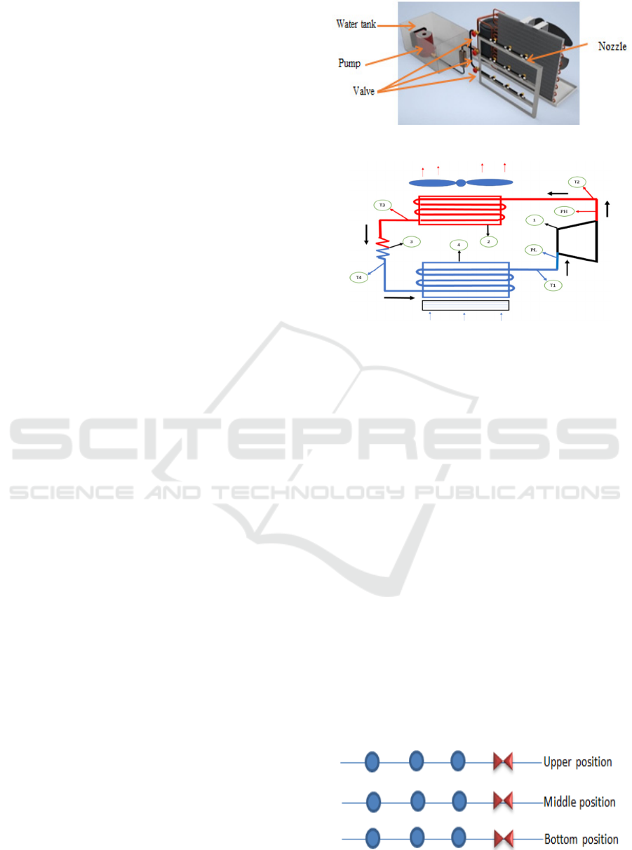
nozzle as shown in Figure 1 to see the effect of
additional cooling on AC split performance. The
placement of this additional cooling system is behind
the condenser / in front of the cooling blower in the
form of water spray through the nozzle. The water
used is the result of air condensation from the air
conditioner itself, collected, pumped and reused to
cool the condenser in the same way.
Figure 1: Design.
Figure 2: Measurement position design.
The test will be carried out based on variations in
horizontal position of the nozzle and the time of
spraying. The 3 nozzles horizontal position means;
top, middle, and bottom row. The spraying time
variation is the length of spraying time the condenser
is sprayed, consecutively 1, 2 and 3 minutes. For the
data collection will use several instruments, such us
thermocouple to take temperature data, voltmeter to
take current and voltage data and pressure gauge
which is directly added on the refrigeration machine
to determine the low and high pressures that’s occur.
The test conditions are:
1. Average room temperature 30
0
C
2. Room: Applied Refrigeration Laboratory,
Mechanical Engineering, Bali State
Polytechnic
3. Condition of room: 6 x 6 x 3.5, 2 doors glass,
8 glass windows, 1 x 2 m equipped with
curtain
4. Average voltage: 225 Volt
5. Stuffs: 3 bookcases with books inside and
several other tools
6. Cos Ø : 0.8
7. Data taken every 5 minutes for 1 hour
8. Layout of nozzle as figure 3
Figure 3: Layout of nozzle.
iCAST-ES 2021 - International Conference on Applied Science and Technology on Engineering Science
24
3 RESULT AND DISCUSSION
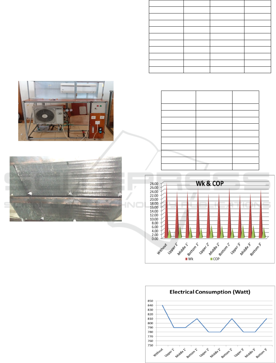
The results that have been achieved are a set of test
equipment consisting of 1 set of split AC 1 Pk,
refrigerant R410a, 840 watts, low pressure 160-170
psi, 4.6 Ampere where these results are in accordance
with the specifications of this cooling machine. The
installation of the pressure gauge is to determine the
high pressure and low pressure that occurs in the
system and the thermocouple that has been installed
to determine the temperature at each position properly
on the test instrument as shown in Figures 4 and 5.
Figure 4: Test equipment.
Figure 5: Nozzel.
The next step is to collect data by measuring pressure,
temperature, voltage and current. To see the
differences that occur, several variations were tested.
The variations made for the position of the nozzle and
time of spraying where 3rd nozzles will be placed
horizontally. For the spraying time, 3rd variations
horizontal will be carried out, namely 1, 2 and 3
minutes. The test will take place with 9 variations,
when the 1st test without additional coolant to test the
initial ability of the cooling machine, 2
nd
, 5
th
and 8
th
for the top horizontal nozzle with a spraying time of
1 minute, 3
rd
, 6
th
and 9
th
for the top horizontal nozzle
with a spraying time of 2 minutes and 4
th
, 7
th
and 10
th
for the top horizontal nozzle with a spraying time 3
minutes.
From the results of the tests carried out, the results
are as shown in the table and figure below:
Table 1: Comparison ER, Wk and COP.
Condition ER Wk
(
k
j
/k
g)
COP
Without 122.99 28.13 4.37
U
pp
er 1 138.86 23.6 5.88
Middle 1 136.71 23.66 5.78
Bottom 1 130.33 25.74 5.06
Upper 2 144.39 22.40 6.44
Middle 2 141.39 22.68 6.23
Bottom 2 130.56 25.31 5.16
U
pp
er 3 145.77 22.02 6.62
Middle 3 143.61 22.62 6.35
Bottom 3 133.40 24.56 5.43
Table 2: Comparison Electrical Consumption & COP.
Condition Electrical
Consumption
COP
Without 840 4.37
U
pp
er 1 790 5.88
Middle 1 790 5.78
Bottom 1 810 5.06
Upper 2 780 6.44
Middle 2 780 6.23
Bottom 2 810 5.16
U
pp
er 3 780 6.62
Middle 3 780 6.35
Bottom 3 810 5.43
Figure 6: Comparison Work of Compression (Wk) &
Coefficient of Performance (COP).
Figure 7: Electrical Consumption.
The Effect of Condenser Cooling to Coefficient of Performance (COP) and Electrical Consumption on AC Split
25

Based on table 1 and Figure 6 above, it is known
that the COP value of the 1 Pk R410a split AC system
before the additional cooling system on the condenser
is turned on the COP result of 4.37. After the
additional cooling system is turned on, the horizontal
nozzle on top, middle and bottom rows for 1 minute
spray the COP results of 5.88, 5.78 and 5.06. In the
5th variation where the additional cooling system will
spray water for 2 minutes, the COP is 6.44, 6.23 and
5.16, respectively. In the 8th variation where the
additional cooling system will spray water for 3
minutes, the COP values are 6.62, 6.35, and 5.43. The
changes the values of COP with the addition of
cooling system in condenser are quite significant due
to the reduced compression work which affects the
COP value.
Based on Figure 7, it’s known that the power
consumption of the 1 PK R410a split system before
the additional condenser cooling system is turn on,
the power consumption is 0.84 watts and after the
condenser additional cooling system is turn on in the
top and middle horizontal nozzles for 1 minute, the
power consumption decrease to 0.79 watts but the
value of power consumption is 0.81 watts at the
bottom row horizontal of the nozzle. Similarly, for
spraying 2 minutes, the top row and the middle
horizontal nozzles are 0.78 watts but in the bottom
row it increases to 0.81 watts. In 3 minutes of
spraying, the power consumption is 0.78 watts on the
top and middle horizontal nozzles while the bottom
row is 0.81. So in general the value of power
consumption after the condenser auxiliary cooling
system is turned on is smaller than when the
condenser auxiliary cooling system is turned off.
These changes occur because the compressions work
(Wk) decreases where the compression work is the
work done by the compressor using electric power.
4 CONCLUSIONS
Within the limitations of materials and time to
experiment, the results obtained in this work, can be
summarized that there is an increase in AC
performance by 34% in the additional cooling system
working especially on the horizontal upper nozzle
which sprays water for 1, 2 and 3 minutes with a
decrease in electrical consumption of 3Watt hour in
average. From the results above, the test will be
continued by testing the spray with the nozzle in the
vertical direction and adding cooling fins to the
compressor.
REFERENCES
Alhamdo, Mohammed H., Maathe A. Theeb, and Jaafar J.
Abdulhameed. 2015. “Using Evaporative Cooling
Methods for Improving Performance of an Air-Cooled
Condenser.” Universal Journal of Mechanical
Engineering 3(3):94–106. doi:
10.13189/ujme.2015.030304.
Ardita, I. N., and I. W. A. Subagia. 2018. “The Application
of Condensate Water as an Additional Cooling Media
Intermittently in Condenser of a Split Air
Conditioning.” Journal of Physics: Conference Series
953:012059. doi: 10.1088/1742-6596/953/1/012059.
Patel, Rupal, and Beena Sheth. 2015. “Evaporative Cooling
of Water for Indirect Air Cooling.”
Porumb, Bogdan, Mugur Bălan, and Raluca Porumb. 2016.
“Potential of Indirect Evaporative Cooling to Reduce
the Energy Consumption in Fresh Air Conditioning
Applications.” Energy Procedia 85. doi:
10.1016/j.egypro.2015.12.224.
Ridhuan, Kemas, and I. Gede Angga Juniawan. 2014.
“PENGARUH MEDIA PENDINGIN AIR PADA
KONDENSOR TERHADAP KEMAMPUAN KERJA
MESIN PENDINGIN.” Turbo : Jurnal Program Studi
Teknik Mesin 3(2). doi: 10.24127/trb.v3i2.11.
Rif, Muhammad, and Kampus Bina Widya Km. 2016.
“Potensi Air Kondensat Sebagai Media Pendingin
Untuk Aplikasi Modul Evaporative Cooling Terhadap
Performansi AC Split 1 PK.” 3:5.
Silalahi, Benny Sarihot Tua, Tri Ayodha Ajiwiguna, and M.
Ramdlan Kirom. 2018. “Studi Pendingin Evaporatif
Untuk Pendinginan Air.” eProceedings of Engineering
5(3).
iCAST-ES 2021 - International Conference on Applied Science and Technology on Engineering Science
26
