
Experimental Study of Shear Strength of
Purus Lobang Berkait (PLB): Masonry Wall
Marwahyudi
1,2 a
, Senot Sangadji
1b
, Halwan Alfisa Saifullah
1c
and Stefanus Adi Kristiawan
1d
1
Civil Engineering Department, Faculty of Engineering, Sebelas Maret University, Surakarta, Indonesia
2
Sahid University, Jl. Adi Sucipto, Surakarta Indonesia
Keywords: Brick, Bed Joint, Head Joint, Masonry, Shear Strength.
Abstract: The earthquake caused damage to buildings, especially simple houses that were not designed according to
engineering rules. Damage caused by earthquakes is often found in the form of cracks to the collapse of
masonry walls. Damage due to earthquake forces can be anticipated by increasing the strength of columns,
beams, and brick walls. Especially for brick walls, this can be done by increasing the strength of the brick
unit, mortar, and brick design that optimizes the function of the mortar. The regular brick stacking pattern
produces a square bed joint and head joint area, while the hook-hole purus brick stacking pattern produces a
square bed joint and an upright cylindrical head joint that connects from top to bottom. This study aims to
determine the effectiveness of the use of PLB masonry in increasing the shear strength of the wall through
laboratory tests using two groups of test objects. Laboratory test results were analysed to determine the shear
strength of masonry walls based on the SNI formula. Based on the results of laboratory tests, it can be
concluded that PLB bricks have a strength of 13.64% greater than ordinary bricks.
1
INTRODUCTION
Indonesia is an earthquake-prone area. Data from the
National Disaster Management Agency (BNPB)
March 22, 2021, shows 1830 natural disasters caused
by earthquakes, volcanic eruptions, forest and land
fires, droughts, floods, landslides, tidal waves. The
above incident resulted in 409 deaths, 3448 houses
were seriously damaged and 88 damaged health
facilities (BNPB, March 2021). The BNPB data
illustrates that most of the damage occurred in
residential houses where most of these buildings were
not designed according to engineering rules so they
were classified as Non-Engineering Building (NEB).
Residential construction practices that do not meet
engineering rules are often encountered in the
community in the form of using very low-quality
concrete due to the uncontrolled mixing of materials
(Figure 1).
The use of plain reinforcement and wide stirrups,
exceeding the design requirements (Figure 2).
a
https://orcid.org/0000-0002-9917-761X
b
https://orcid.org/0000-0001-5131-6273
c
https://orcid.org/0000-0001-5106-3544
d
https://orcid.org/0000-0002-0312-4960
Figure 1: Imperfect concrete manufacture.
Figure 2: Plain reinforcement and wide stirrups.
220
Marwahyudi, ., Sangadji, S., Saifullah, H. and Kristiawan, S.
Experimental Study of Shear Strength of Purus Lobang Berkait (PLB): Masonry Wall.
DOI: 10.5220/0010748300003113
In Proceedings of the 1st International Conference on Emerging Issues in Technology, Engineering and Science (ICE-TES 2021), pages 220-226
ISBN: 978-989-758-601-9
Copyright
c
2022 by SCITEPRESS – Science and Technology Publications, Lda. All r ights reserved
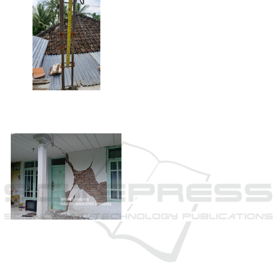
Figure 3: The details of the distribution reinforcement do not
meet the requirements.
Details of reinforcement at joints that do not meet the
distribution length (Figure 3) and others.
Figure 4: Damage caused by an earthquake.
The strength of the NEB needs to be increased so
that occupant safety is guaranteed. This increase can
be done by increasing the strength of the concrete
elements and their reinforcement and/or increasing
the strength of the walls. Columns and beams form a
frame structure system that supports the building and
walls as a filler for the frame structure can also play a
role in contributing to the strength of the building.
Increasing the strength of the concrete beam-column
can be through increasing the quality of the
compressive strength of concrete and installing
concrete reinforcement that meets the design
requirements. Increased wall strength through
increasing the strength of bricks, mortar in the bed
joint and head joint area. Several studies have shown
that portals with infill bricks have better strength than
portals without infilling bricks. It can be concluded
that bricks have a contribution in contributing to the
strength of the building(Cavaleri & Di Trapani, 2015;
Farooquddin, 2000; Nguyen & Meftah, 2014). This
means that an increase in the overall masonry strength
can increase the strength of the infill portal structure.
The strength of a masonry wall in resisting lateral
forces (earthquake) can be analyzed by modeling it as
a strut element in which the series of bricks is
simplified into a diagonal strut plane. Some of the
lateral forces acting on the joint are distributed to the
wall as an axial force received by the diagonal plane
of the strut. Approaches in strut modeling can be
grouped into two, namely wall modeling as a diagonal
plane of one strut and multi-strut. The struts method
is proven to be effective in analyzing the contribution
of masonry walls in bearing lateral forces (Bolea,
2016; Di Trapani et al., 2018; El-dakhakhni, 2017; El-
Dakhakhni et al., 2003).
The strength of the diagonal struts model is
influenced by several parameters related to
mechanical, geometrical, and empirical properties of
masonry infilled frame structure. One of the
mechanical properties that are taken into account in
determining the strength of the diagonal struts is the
shear strength. The shear strength of a series of bricks
is also influenced by the bed and head joint bonds.
The bed joint bond provides strength in the vertical
direction and the head joint bond provides strength in
the horizontal direction. Both strengths are required
in a masonry wall assembly. The stronger the bed and
head joint bonds, the more strength the masonry wall
will be.(Francisco J. Crisafulli, 1997b; Pallarés et al.,
2021; Smyrou et al., 2011).The arrangement of PLB
bricks will provide a different bed and head joint
pattern from ordinary bricks. The mortar that fills the
hollow of the brickwork produces a peg that acts to
resist the horizontal force. The effect of these pegs is
similar to that of interlocking masonry with holes
filled with sand mortar as in the study conducted by
Joyklad(Joyklad & Hussain, 2019).
PLB bricks have a simple and flat shape making
them easier to organize in storage. The basic materials
and methods of burning are the same as ordinary
bricks, no special furnace is required, so all brick
craftsmen can make them. The volume of material
used in the manufacture is less than ordinary bricks.
Similar studies with PLB bricks are still few so it is
necessary to conduct research that produces
applicable and conclusive designs for problems that
are also easily mass-produced.
This study aims to determine the effectiveness of
mortar post-filling PLB masonry in increasing the
shear strength of the wall. The shear strength of the
PLB masonry will be compared with the shear
strength of the ordinary masonry to determine the
contribution of the mortar post.
Experimental Study of Shear Strength of Purus Lobang Berkait (PLB): Masonry Wall
221
2
MATERIALS AND METHODS
The test objects used were divided into two groups.
The first group is a PLB brick panel and the second
group is a regular model brick panel as a control.
2.1 Making Test Specimen
The normal brick panel (N) is made of ordinary
masonry measuring 10-centimeter wide, 20-
centimeter long, and 3-centimeter thick (see Figure
5). Meanwhile, PLB panels are made of hole bricks
of the same size as normal bricks but have a 3-
centimeter diameter hole (see Figure 6). The two
types of bricks are arranged to form a panel
measuring 60x60 cm (see Figure 7-8). The number of
test objects is shown in table 1.
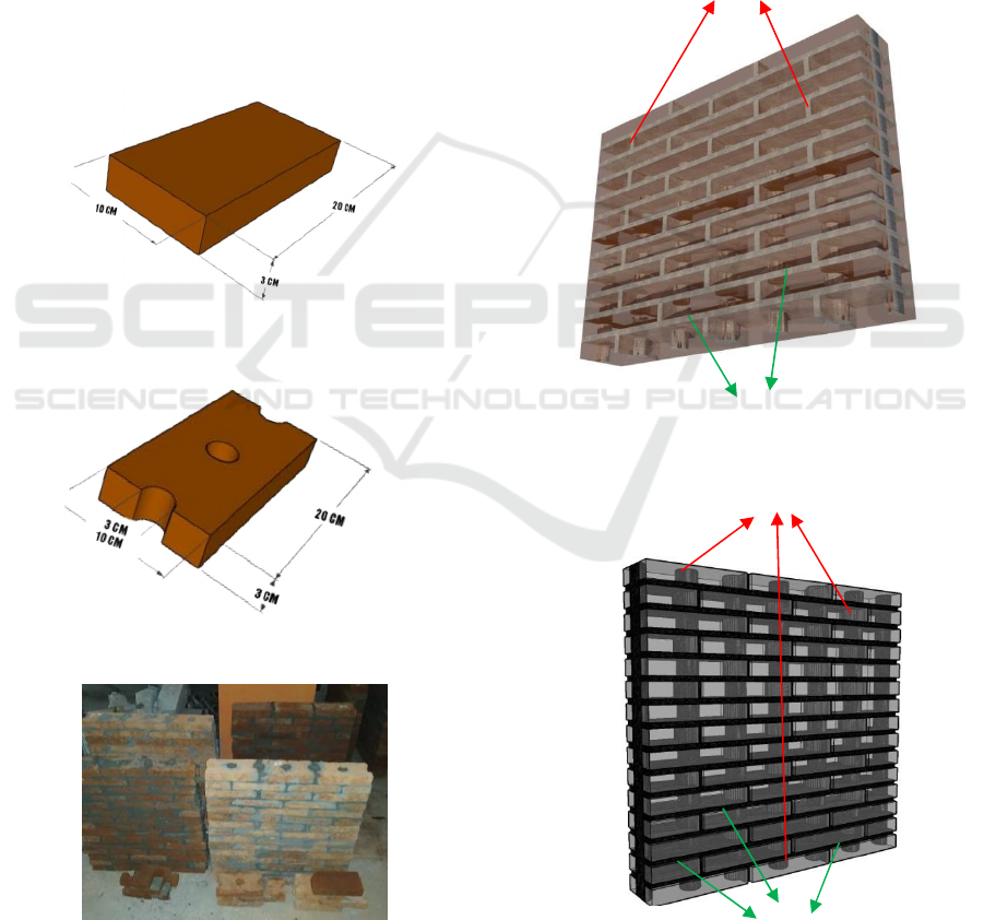
Figure 5: Ordinary bricks.
Figure 6: Purus lobang berkait (PLB)Brick.
Figure 7: Manufacture of test specimens.
Figures 8 and 9: show the results of a series of
ordinary and PLB brick panels.
a) A series of panels made of ordinary bricks
produces the same bed joint and head joint
pattern, namely a rectangular area (see Figure 8).
b) The panel series of PLB bricks produces a
rectangular bed joint pattern and the head joint
has a cylindrical plane pattern that is connected
from the top to the bottom (see Figure 9).
c) The head joint pattern in the PLB is expected to
be able to withstand the lateral force
(earthquake) in the horizontal direction on the
brick series.
Head Joint
Bed Joint
Figure 8: Illustration of bed joint and head joint pattern.
Head Joint
Bed Joint
Figure 9: Illustration of bed joint and head joint pattern.
ICE-TES 2021 - International Conference on Emerging Issues in Technology, Engineering, and Science
222
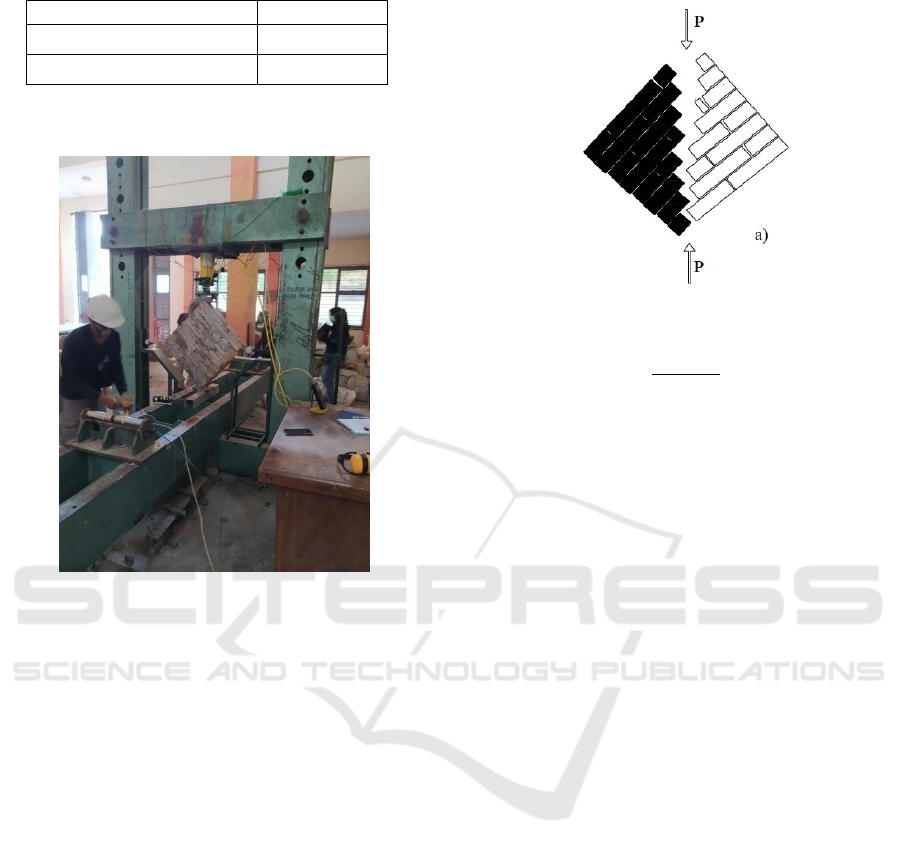
Table 1: Number of the test specimen.
Bric
k
T
y
pe Dia
g
onal Shea
r
Ordinar
y
(N) 3 specimen
Purus Loban
g
Berkai
t
(PLB) 3 specimen
2.2 Testing
Figure 10: Diagonal shear strength test.
The diagonal shear test procedure is as follows. First,
the test object is painted white to make it easier to
observe the cracks that occur. Then the test object is
placed in a diagonal position (see Figure 10) and the
end position of the test object must be in a vertical
line with the load cell or load jack. Followed by the
installation of the dial gauge on the right and left ends.
This tool serves as a strain gauge when receiving a
force. Loading is done by giving a force that increases
regularly. Loading starts from 0 and increases by 50
kgf until it is destroyed or the device is no longer able
to read. At every 50 kgf increase, the condition of the
specimen was observed and the strain was recorded.
Crack development is monitored from the beginning
of loading until failure. Then the results of the test are
analyzed.
2.3 Shear Stress
Shear Stress calculated according to the Indonesian
National Standard formula(SNI O3-4166-1996,
1996).
Diagonal shear strength formula:
Figure 11: Diagonal shear crack pattern(Borri et al., 2015).
f
vd
=
0,707𝑃𝑢+𝑊
𝑥(1 − µ) (1)
𝐴
𝐴
= ℎ 𝑥 𝑏 (1.2)
Where:
Pu = Maximum test load in N
W = Mass of internal aids N
b = Brick width in mm
h = The length of the shear plane of the
brick in mm
µ = Friction coefficient 0.3
A =Shear cross-sectional area (hxb) in mm2
The formula above shows that the diagonal shear
strength value is the ability of the magnitude of the
force in cutting across the diagonal area with the
length of the diagonal of the panel as h and the
thickness of the panel as b. This formula will be
effective if the crack of the test specimen has a
diagonal pattern so that the crack length is assumed to
be equal to the diagonal (as h). However, if the crack
pattern is not diagonal, then the proposed conversion
value (h) is derived from the length a of the crack or
the conversion of the magnitude of the force if the
crack pattern is in the diagonal direction.
3
RESULTS AND DISCUSSION
Masonry walls are made of bricks and mortar that
form a homogeneous whole. The bricks function as
filler and mortar as an adhesive for the bed joint and
head joint. Some researchers state that the wall is a
homogeneous series of marble and bricks in resisting
forces (Chopra, 2012; Francisco J. Crisafulli, 1997a;
Gambarotta & Lagomarsino, 1997; Miha Timocevic,
2006; Pauly, 2010).
Experimental Study of Shear Strength of Purus Lobang Berkait (PLB): Masonry Wall
223
The pattern of cracks/collapse that occurs between
ordinary panels and PLB panels has its
characteristics. The crack pattern starts from the area
that resists the force to the weak area. Weak areas are
found in the joints between mortar and bricks
(Cavaleri & Di Trapani, 2015; Lucchesi M, 2008;
Tomaževič, 2009). Pola ini sangat menarik untuk
diobservasi dan analisis.
The brick panels that receive a diagonal force
have a diagonal crack pattern that passes through the
head joint and bed joint (see Figure 11).
There are crack patterns that are produced in the
laboratory, starting from the top and some starting
from the bottom of the test object (as shown in
Figures 12 and 13).
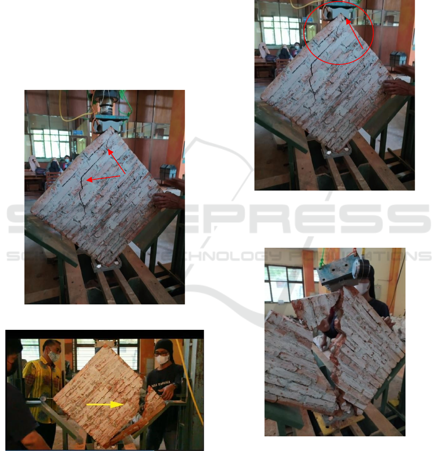
Figure 12: Ordinary brick crack pattern.
Figure 13: Ordinary brick crack pattern.
The pattern of cracks/failure of normal bricks tends to
be lateral which is not following theoretical estimates.
The pattern of cracks that occurs predominantly in the
horizontal direction may be caused by the placement
of the corners of the test specimens not being perfect
at the ends of the brick panels so that during the
loading process the panels move slightly (see Figure
14). This movement causes the position of the panel to
shift slightly which results in the force not being in a
perfect diagonal direction and causing some of the
crack patterns to be horizontal.
Figure 14: The placement of the corners is not perfect.
The crack pattern of diagonal compression test
results on purus lobang berkaitbrick specimens.
Figure 15: PLB brick crack pattern.
ICE-TES 2021 - International Conference on Emerging Issues in Technology, Engineering, and Science
224

Figure 16: PLB brick crack pattern.
The PLB crack/failure pattern is dominant in the
vertical direction with the crack pattern crossing the
bed joint and brick area. The cracks produced by PLB
bricks have a diagonal tendency. Figure 15
destruction of the panel above the second branch
because at the time of failure, the end of the panel
received a collision from the auxiliary tool so that the
crack direction pattern was in the same direction as
the bed joint. Figure 16 shows the failure of the top
plane not right at the end because the placement is not
perfect at an angle.
The results of the diagonal panel shear test in this
study showed a pattern of cracks through the bed
joint, head joint, and bricks. This pattern occurs in
both types of bricks. This test is very precise to
determine the diagonal shear strength of wall panels
from homogeneous mortar and brick bonds.
Meanwhile, to determine the shear strength of the bed
joint and head joint, a horizontal shear test is carried
out.
A lateral load-deformation diagram resulting from
laboratory tests.
Figure 17:
Load-
deformation
diagram.
This diagram shows that at the beginning of loading
shows a linear strength increases in proportion to the
deformation up to a certain point. After that, the
increase is not consistent with the deformation and
makes the non-linear direction until the total collapse.
Figure 17 shows that ordinary bricks (N) after
linear conditions increase in stiffness. This condition
is possible because the position of the elbow at the
end is still loose and unstable. At the time of loading
from the beginning to the end, the linear elbow at the
end experiences a movement that affects the stiffness
value. Then after that, the condition is stable which
increases the stiffness of the panel.
Normal bricks are in linear condition at a force of
0-450 kgf with deformation of 0.00 – 0.59 mm. Non-
linear conditions at 450-1550 kgf with deformation
0.59 – 2.73 mm, failure at 1300-1550 kgf. PLB bricks
are in linear condition at a force of 0-1000 kgf with
deformation of 0.00 – 0.64 mm. Non-linear
conditions at 1000-2150 kgf with deformation 0.64 –
2.79 mm, failure at 2000 -2200 kgf.
The results of the calculation of the diagonal shear
strength are summarized as follows:
Table 2: The results of the calculation of the shear strength
of the diagonal panel.
T
ypes of bricks
Early crack
(MPa)
Maximum shear
strength (MPa)
Average
(MPa)
Ordinary N 1
0,028 0,088
0,110
Ordinary N 2
0,040 0,138
Ordinary N 3
0,034 0,105
Lobang PLB 1
0,062 0,130
0,125
Lobang PLB 2
0,056 0,118
Lobang PLB 3
0,059 0,128
The results of the calculation of this study are
following the calculations carried out by Joyklad,
with the results of 0.096 - 2.183 MPa (Joyklad &
Hussain, 2019).
Figure 18: PLB brick-shaped mortar pegs.
2500
2000
Batu
bata
(N)
1500
1000
500
Batu
bata
(PLB)
Deformasi (mm)
Beban (kgf)
0,00
0,20
0,40
0,60
0,80
1,00
1,20
1,40
1,60
1,80
2,00
2,20
2,40
Experimental Study of Shear Strength of Purus Lobang Berkait (PLB): Masonry Wall
225

One of the reasons for increasing the strength of
PLB bricks is the formation of a cylindrical mortar
post in a vertical direction as shown in Figure 18. As
a validation, it is necessary to ensure the horizontal
shear test.
4
CONCLUSIONS
This research opens new insight that the strength of
masonry wall panels is influenced by the design of the
bricks that increase the function of the mortar. PLB
brick peg mortar increased the diagonal shear strength
of
the panel by 13.64% compared to ordinary bricks (N).
Tests in the laboratory showed that not all of the
crack patterns were following the theory. In future
research, more attention is paid to the setup of the test
object according to the standard to get results that are
closer to events in the field. In addition, numerical
studies are also needed as controls.
ACKNOWLEDGEMENTS
We would like to thank the laboratories of Universitas
Sebelas Maret Surakarta and Universitas Veteran
Bangun Nusantara for lending tools and places to
carry out the research. Also to the NEB research team
who provided input in the implementation of tests and
shared photos of earthquake damage documents.
REFERENCES
BNPB (2021). National Disaster Management Agency.
Jurnal Dialog Penanggulangan Bencana. 2087-636X.
Bolea, O. (2016). The Seismic Behaviour of Reinforced
Concrete Frame Structures with Infill Masonry in the
Bucharest Area. Energy Procedia, 85(November 2015),
60–76. https://doi.org/10.1016/j.egypro.2015.12.275
Borri, A., Castori, G., & Corradi, M. (2015). Determination
of Shear Strength of Masonry Panels Through Different
Tests. International Journal of Architectural Heritage, 9
(8), 913–927. https://doi.org/10.1080/15583058.2013.
804607
Cavaleri, L., & Di Trapani, F. (2015). Prediction of the
additional shear action on frame members due to infills.
Bulletin of Earthquake Engineering, 13(5), 1425–1454.
https://doi.org/10.1007/s10518-014-9668-z
Chopra, A. K. (2012). Dynamics Of Structures.
Di Trapani, F., Shing, P. B., & Cavaleri, L. (2018).
Macroelement Model for In-Plane and Out-of-Plane
Responses of Masonry Infills in Frame Structures.
Journal of Structural Engineering (United States),
144(2). https://doi.org/10.1061/(ASCE)ST.1943-
541X.0001926
El-dakhakhni, W. (2017). Three-Strut Model for Concrete
Masonry-Infilled Steel Frames. 9445(February 2003).
https://doi.org/10.1061/(ASCE)0733-9445(2003)129
El-Dakhakhni, W. W., Elgaaly, M., & Hamid, A. A. (2003).
Three-Strut Model for Concrete Masonry-Infilled Steel
Frames. Journal of Structural Engineering, 129(2),
177– 185. https://doi.org/10.1061/(ASCE)0733-
9445(2003)129:2(177)
Farooquddin, S. (2000). Lateral Stiffness of Infilled frame
with Door & Window Openings for varying Modulus of.
7–9.
Francisco J. Crisafulli. (1997a). Seismic behaviour of
reinforced concrete structures with masonry infills. In
Civil Engineering.
Francisco J. Crisafulli. (1997b). Thesis
fulltext_masonry.pdf. University of Canterbury.
Gambarotta, L., & Lagomarsino, S. (1997). Damage
models for the seismic response of brick masonry
shear walls . Part ii : the continuum model and its
applications.26(March 1996), 441–462.
Joyklad, P., & Hussain, Q. (2019). Axial compressive
response of grouted cement–clay interlocking hollow
brick walls. Asian Journal of Civil Engineering, 20(5),
733–744. https://doi.org/10.1007/s42107-019-00140-2
Lucchesi M. (2008). Masonry Constructions:
Mechanical Models and Numerical Applications. In
Masonry Constructions: Mechanical Models and
Numerical Applications. https://doi.org/10.1007/978-3-
540-79111-9 Miha Timocevic. (2006). Earthquake
Resistant Design of Masonry Building. Emparial
Collage Press.
Nguyen, T. D., & Meftah, F. (2014). Behavior of hollow
clay brick masonry walls during fire. Part 2: 3D finite
element modeling and spalling assessment. Fire Safety
Journal, 66, 35–45. https://doi.org/10.1016/j.firesaf.
2013.08.017
Pallarés, F. J., Davia, A., Hassan, W. M., & Pallarés, L.
(2021). Experimental and analytical assessment of the
influence of masonry façade infills on seismic behavior
of RC frame buildings. Engineering Structures, 235(Fe
bruary).https://doi.org/10.1016/j.engstruct.2021.112031
Pauly, T. (2010). Seismic Design of Reinforced Concrate
And Masonry Buildings. John Wiley & Sons.
Smyrou, E., Blandon, C., Antoniou, S., Pinho, R., &
Crisafulli, F. (2011). Implementation and verification
of a masonry panel model for nonlinear dynamic
analysis of infilled RC frames. Bulletin of Earthquake
Engineering, 9(5), 1519–1534. https://doi.org/1
0.1007/s10518-011-9262-6
SNI O3-4166-1996. (1996). Geser Dinding Pasangan Bata
Merah Dl Laboratorium. 2, 4166.
Tomaževič, M. (2009). Shear resistance of masonry walls
and Eurocode 6: Shear versus tensile strength of
masonry. Materials and Structures/Materiaux et
Constructions, 42(7), 889–907. https://doi.org/10.
1617/s11527-008-9430-6
ICE-TES 2021 - International Conference on Emerging Issues in Technology, Engineering, and Science
226
