
Beamforming Networks using a Broadband 4x4 Butler Matrix with
Wideband Crossovers and Couplers
Salah Ihlou
1a
, Hafid Tizyi
2b
and Ahmed El Abbassi
1
1
Team Electronics, Instrumentation and Systems Intelligent, Faculty of Science and Technology Moulay Ismail University,
Errachidia, Morocco
2
STRS Laboratory, INPT, Rabat, Morocco
Keywords: Beamforming Network, Miniaturized butler matrix, Schiffman phase shifter, 0 dB crossover.
Abstract: In this work, a novel and miniaturized 4*4 Butler matrix will be presented. This proposed butler matrix
comes with four 3 dB quadrature forward wave coupled line coupler, two 45 Schiffman phase shifter and
one crossover. This BM has been created a centre frequency of 5.8 GHz using FR4 substrate. The crossover
of this BM has substituted with a 0 dB. The proposed BM occupies a total area of (84.74 mm)*(76.56 mm).
It exhibits high isolation and wideband 4x4 Butler matrix designed and simulated by employing a single-
layer FR4 substrate. The return losses are better than 28 dB with its good performance.
a
https://orcid.org/0000-0002-2253-5298
b
https://orcid.org/0000-0003-1582-7732
1 INTRODUCTION
The number of wireless communication system
users, combined with the restricted number of radio-
frequency channels, represents a source of
interference in certain areas. This lowers the
efficiency of wireless transmissions and restricts
their capabilities, such as cellular bandwidth and
frequency efficiency. Several methods, including
innovative antenna arrays, have recently been used
to improve communication efficiency even in
unfavourable environments. There are two
categories of intelligent antenna systems: adaptive
arrays and switched beam systems (Lehne, 1999).
The first is a system that effectively rejects
interference by adjusting to the environment in real-
time and using adaptive algorithms. It is, though,
more complex and requires more signal processing
than the above group. Since the second form does
not employ controllers, it is less powerful and less
expensive than the first. To ensure mobile tracking
in a dynamic environment, a switched beam system
generates several beams and selects the appropriate
beam that produces the strongest signal powerful
from among them. As the mobile travels, this
mechanism shifts from one shaft to another. In
switched-beam antenna systems, the Butler matrix is
a well-known beamforming network. N input ports
and N output ports feed N antennas in an NxN
Butler matrix.
Planar or waveguide technology that could be
used to build the Butler matrix. The Butler matrix
comprises three main components: 3-dB/90
quadrature couplers, crossovers, and phase shifters.
Wideband 3-dB couplers and crossovers are
necessary to achieve wideband features. Microstrip
multi-section branch-line structures were used to
perform these characteristics (Deb et al. 2020).
Several wideband Butler matrix configurations using
Conductor Backed Coplanar Waveguide (CB-CPW)
technology (Abdelghani et al. 2012), Substrate
Integrated Waveguide (SIW) technology (Djerafi
and Wu, 2012), and single layer r planar technology
(Denidni and Libar, 2003) have recently been
published in the literature. The authors of (Denidni,
and Libar, 2003) proposed a Butler matrix for
obtaining a wideband of 250 MHz and return losses
less than 22.05 dB, using regular 3-dB quadrature
couplers and four-section branch-line crossovers.
According to the findings in (Denidni and Libar,
2003), the bandwidth can reach 1.92 and 2.17 GHz
and return losses and isolation are greater than 23
and 26 dB, respectively. Identically, the simulation
Ihlou, S., Tizyi, H. and El Abbassi, A.
Beamforming Networks using a Broadband 4x4 Butler Matrix with Wideband Crossovers and Couplers.
DOI: 10.5220/0010732100003101
In Proceedings of the 2nd International Conference on Big Data, Modelling and Machine Learning (BML 2021), pages 255-259
ISBN: 978-989-758-559-3
Copyright
c
2022 by SCITEPRESS – Science and Technology Publications, Lda. All rights reserved
255
results of the 4x4 Butler matrix are to be presented
in this paper. The matrix operates over a frequency
range of 5.4GHz to 5.95 GHz and provides good
return losses and separation of better than -28.26 dB
at the operating frequency.
2 DESIGN CONFIGURATION
As shown in the layout below, the 4x4 Butler matrix
comes up with four couplers (Hock and
Chakrabarty, 2005), one wideband crossover (Deb et
al. 2020), and two-phase shifters (Zhai, 2014).
The first order microstrip line calculations were
performed manually (Pozar, 2011), and then using
the ADS calculator to optimize them. The
components are based on a 1.6 mm thick FR-4
substrate with a dielectric constant of 4.4.
The output of BM is highly dependent on the
coupler and crossover features; they are each
simulated and configured separately before
combining them to form the Butler matrix's entire
architect using Advanced Design System Simulator.
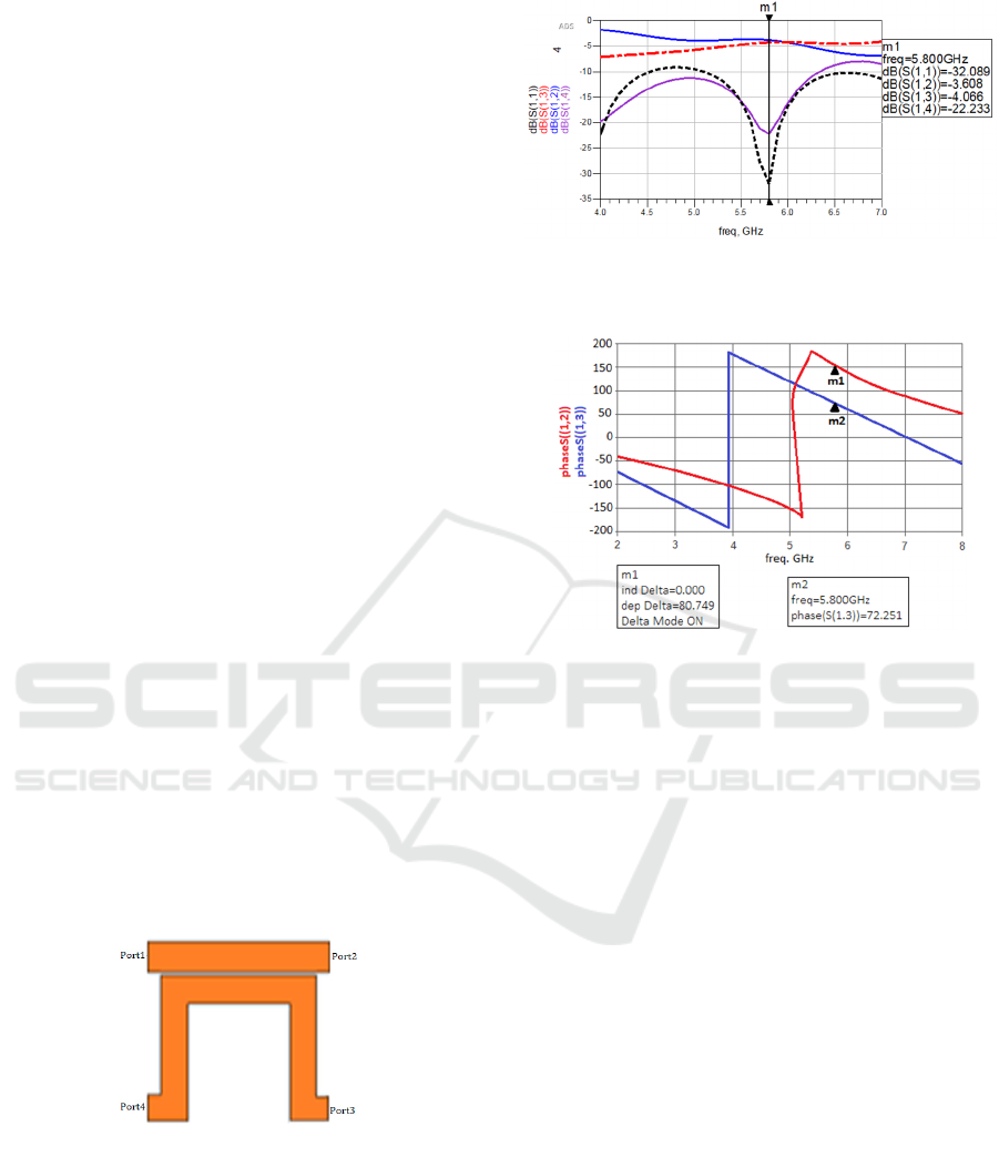
2.1 Coupler
In the BM, the coupler is the most critical
component. It's a -3 dB directional coupler operating
a frequency of 5.8 GHz that splits the input signal
into two equal-amplitude output signals. Input port
1, output port 2 (direct route), port 3 (coupled
channel), and isolated port 4 (Hock and Chakrabarty,
2005) are the four ports.
Figure 1 depicts the proposed coupler's
configuration, while Figure 2 depicts the simulated
S-parameters.
Figure 1: Layout of S-parameters of the coupler
Figure 2: Simulation S11, S12, S13 and S14 of the
coupler.
Figure 3: Simulated S12 and S13 phase difference
between the output ports.
The S14 return loss and S11 isolation, respectively,
are roughly -22,23 dB and -32,08 dB. It's also
apparent that we've got a good match and excellent
operating frequency isolation. At 5.8 GHz, the
coupling is about -3, which means that power on
both output ports is halved. The phase difference
between the output ports is around 72.25°, as
anticipated.
2.2 Phase Shifter
Phase shifters are one of the essential commonly
used methods in RF.
Beamforming nets, Phase discriminators, optical
beam-scanning phased arrays, and other applications
use it. It shifts the signal into a Predetermined step
(Zhai, 2014)
. Figure 4 depicts this.
BML 2021 - INTERNATIONAL CONFERENCE ON BIG DATA, MODELLING AND MACHINE LEARNING (BML’21)
256
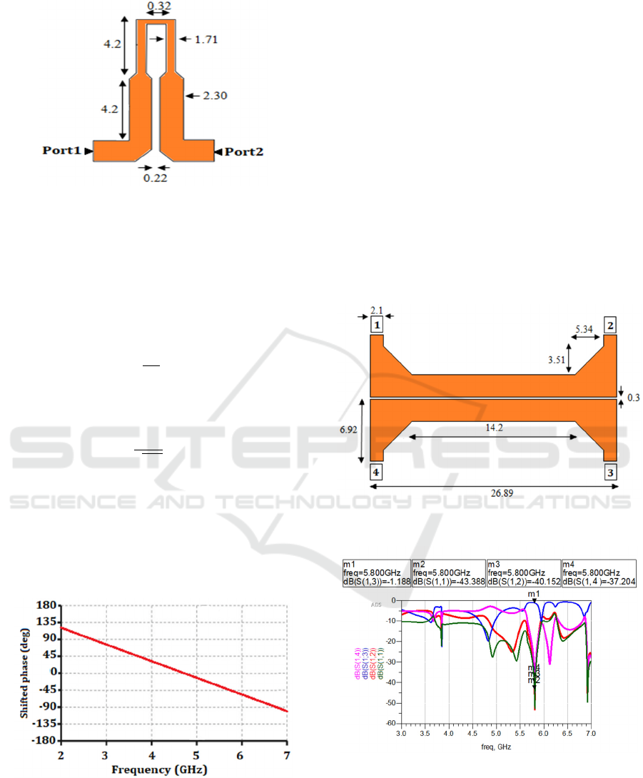
Figure 4: The structure of the Schiffman differential phase
shifter
The phase shifter used is a Schiffman phase shifter,
consisting of two coupled transmission lines with
one folded side. Two 45 phase shifters make up the
BM. The following formulation (Srivastava and
Gupta, 2006) defines the line length corresponding
to the step shift of 45:
ΔL =
(1
)
In a microstrip line, the wavelength is defined as:
where the phase θ change is located.
𝜆 =
(2
)
The wavelength is λ0, and εeff is the microstrip
line's effective dielectric constant. Figure 5 depicts
the phase shifter configuration as well as the
simulation performance. The phase difference
between ports 1 and 2 is about 45 at the operating
frequency.
Figure 5: Simulated phase difference between the ports 1
and 2 of -45° phase shifter
2.3 Crossover
Crossover is the most complicated aspect of
realizing the Butler matrix. In order to avoid
overlapping signals at crossings, the crossover
should be used in a fair degree of separation between
the input ports. As they have four symmetrical
ports, with two inputs and two outputs (Deb et al.,
2020). If every neighbouring port is isolated, then
we get the best crossover configuration.
The geometry and momentum S-parameters of a
potential crossover are shown in Figures 6 and 7,
respectively. It shows that the suggested crossover
has ideal characteristics in terms of isolation and
parameter lack of return. The S11 return loss is -
43.38 dB, indicating that the 5.8 GHz resonant
frequency is a perfect match. -1.18 is the entry
failure from coupling port S13. The coupling ratio is
approximately 0 dB, implying that the power at Port
1's input fully transfers to Port 3. At 5.8 GHz, S12
and S14 are separated by -40.15 dB and -37.20 dB,
respectively.
Figure 6: The structure of the proposed crossover
Figure 7: Simulated return loss S11, insertion loss S13,
isolations S12 and S14 of the crossover.
The suggested BM is shown in Figure 9. It comes
with a miniaturized shifter, coupler, and 0 dB
crossover built-in.
Beamforming Networks using a Broadband 4x4 Butler Matrix with Wideband Crossovers and Couplers
257
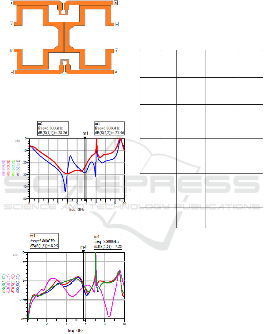
Figure 9: Proposed 4*4 BM
A N*N BM has N input lines and N output lines
(where N is an even number and must be greater
than or equal to 4). Between the output lines of N
unit BM, there is a phase difference.
Figure 10: Simulated S11 and S22 of the four input ports
Figure 11: Simulated insertion losses of the port 1
The virtual coefficients S17, S15, and S18, S16 are
approximately -8 dB and -7 dB, respectively, which
is substantially different from the ideal value of -6
dB. Because of this, the control of port one is also
split between the output ports. We believe the results
obtained are promising.
Table 1: Performance comparison of proposed work with
exciting work.
Ref freq
(GHz
)
Substrate
material
Total size
mm
2
Return
Loss
S11(dB)
(Rifi et
al.
2018)
5.8 FR4 90.61×96.54 -24.69
(Nacho
uane et
al.
2014)
2.4 FR4 173.7×173 -35
(
Abdel
ghani
et al.
2012)
5.8 RO4003 90*70 <-11
(Bhow
mikand
Moyra,
2017)
2.5 FR4 115.18*64.4 -20
This
work
5.8 FR4 44.25 *
39.92
-28.26
The comparison shows that the BM has good
characteristics in terms of return loss and total size,
as shown in Table 1.
3 CONCLUSIONS
As a conclusion, a new wideband 4x4 Butler matrix
has been analysed, developed, and simulated. The
high bandwidth is reached by using broadband
systems such as crossovers and couplers. Its good
performance makes it ideal for wireless
communication systems as beamforming for multi-
beam antenna arrays for angle diversity to minimize
interference.
Experimentation is needed to validate the design.
As compared to other structures in the literature,
the proposed matrix has robust characteristics in
terms of substrate material, return loss and total size,
as shown in Table 1.
BML 2021 - INTERNATIONAL CONFERENCE ON BIG DATA, MODELLING AND MACHINE LEARNING (BML’21)
258

REFERENCES
Lehne, P. H. (1999). An overview of smart antenna
technology for mobile communications systems. IEEE
Comm. Surveys, fourth Quarter, 2(4).
Deb, P. K., Moyra, T., & Bhattacharyya, B. K. (2020).
Designing of Miniaturized 4× 4 Butler Matrix Using
Coupled Line Coupler and Schiffman Phase
Shifter. Iranian Journal of Science and Technology,
Transactions of Electrical Engineering, 1-10.
Abdelghani, L. M., Denidni, T. A., & Nedil, M. (2012,
June). Ultra-broadband 4× 4 compact Butler matrix
using multilayer directional couplers and phase
shifters. In 2012 IEEE/MTT-S International
Microwave Symposium Digest (pp. 1-3). IEEE.
Djerafi, T., & Wu, K. (2012). A low-cost wideband 77
GHz planar Butler matrix in SIW technology. IEEE
Transactions on Antennas and Propagation, 60(10),
4949-4954.
Denidni, T. A., & Libar, T. E. (2003, September).
Wideband four-port Butler matrix for switched multi-
beam antenna arrays. In 14th IEEE Proceedings on
Personal, Indoor and Mobile Radio Communications,
2003. PIMRC 2003. (Vol. 3, pp. 2461-2464). IEEE.
Hock, G. C., & Chakrabarty, C. K. (2005, December).
Design of a 5.8 GHz directional coupler using an
electronic design automation tool. In 2005 Asia-
Pacific Conference on Applied Electromagnetics (pp.
4-pp). IEEE.
Zhai, Y., Fang, X., Ding, K., & He, F. (2014).
Miniaturization design for 8× 8 Butler matrix based on
back-to-back bilayer microstrip. International Journal
of Antennas and Propagation, 2014.
Pozar, D. M. (2011). Microwave engineering. John Wiley
& sons.
Srivastava, G. P., & Gupta, V. L. (2006). Microwave
devices and circuit design. PHI Learning Pvt. Ltd.
Rifi, M., Tizyi, H., Terchoune, H., & Elmarini, S. (2018).
Switched beam smart antenna based on a planar 4x4
butler matrix for wireless power transfer at 5.8
GHz. Revue Méditerranéenne des
Télécommunications, 8(2).
Nachouane, H., Najid, A., Tribak, A., & Riouch, F. (2014,
April). Broadband 4× 4 Butler matrix using wideband
90° hybrid couplers and crossovers for beamforming
networks. In 2014 International Conference on
Multimedia Computing and Systems (ICMCS) (pp.
1444-1448). IEEE.
Bhowmik, P., & Moyra, T. (2017). Modelling and
validation of a compact planar butler matrix by
removing crossover. Wireless Personal
Communications, 95(4), 5121-5132.
Beamforming Networks using a Broadband 4x4 Butler Matrix with Wideband Crossovers and Couplers
259
