
View-based Modelling: Behaviour Specification based on UML
Concept
Chaimae Ouali-Alami
a
, Abdelali El Bdouri, Nisrine Elmarzouki and Younes Lakhrissi
b
SIGER Laboratory, Sidi Mohamed Ben Abdellah University, Fez, Morocco
Keywords: Model Composition, Behavioural, Fusion, Modelling, UML, VUML.
Abstract: Point-of-view modelling is an object-oriented modelling approach aimed at analysing and designing complex
systems with an approach centred around the actors interacting with the system. The UML profile called
VUML (View-based UML) allows the development of a single shareable model based on views associated
with the actors' points of view. However, the work done on the VUML profile does not cover the behavioural
aspects of modelling. Indeed, – by proposing the concept of a multi-view class – VUML deals with the
structural elements related to the composition of views, and the sharing of static data without taking into
account how those views will react or how to synchronize them to represent the behaviour of multi-view
objects (instances of a multi-view class). The work carried out in this article seeks to fill this gap by providing
the VUML profile with new mechanisms to express the behaviour of a system. We focused on the behaviour
of multi-view objects described by state machines that require adaptations of UML modelling concepts.
1 INTRODUCTION
Despite the evolution of design techniques in the area
of software engineering, the construction of complex
computer systems remains a complicated task. In this
context, it is often impossible to construct a global
model that takes all needs into account
simultaneously. In reality, the application is broken
down into several partial models, thus reducing the
size and complexity of the system. However, initiate
a compositional phase to obtain the final version of
the application.
The objective of this paper is to address the
problem of behavioural specification in the
framework of the VUML profile. We focus on
describing the individual behaviour of multi-view
objects, each consisting of a set of view objects
encapsulating data specific to each actor. This
treatment amounts to treating the following two
crucial points: the specification of the behaviours of
objects-view on the one hand and the composition of
these behaviours to form the global behaviour of the
multi-view object on the other hand.
The difficulty of the problem lies in the fact that
the views are developed separately according to the
a
https://orcid.org/0000-0003-3862-9149
b
https://orcid.org/0000-0003-2718-7090
VUML approach and are then composed in the fusion
phase to form the overall behaviour of multi-view
objects.
The compromise that seems the best is to propose
an approach that allows the greatest possible freedom
in the development of views, and at the same time to
provide a means to facilitate fusion.
To solve this problem, we propose to reuse the
mechanisms for specifying behaviour and
communication between UML objects.
In this paper, we describe an approach that
involves using standard UML mechanisms to
determine the behaviour of VUML view objects and
communication between views. It is, therefore,
necessary to specify the behaviour of objects seen by
state machines communicating through signal
exchanges or method calls. It proposes a technique
based on a separate description and then coordinates
the state machines of the objects seen and base.
To obtain a directly executable specification, we
used the Omega UML profile for which simulation
and verification tools exist. We also propose an
approach extending associated with VUML to
explain how to produce the offered state machines.
154
Ouali-Alami, C., El Bdouri, A., Elmarzouki, N. and Lakhrissi, Y.
View-based Modelling: Behaviour Specification based on UML Concept.
DOI: 10.5220/0010730100003101
In Proceedings of the 2nd International Conference on Big Data, Modelling and Machine Learning (BML 2021), pages 154-160
ISBN: 978-989-758-559-3
Copyright
c
2022 by SCITEPRESS – Science and Technology Publications, Lda. All rights reserved
We illustrate these proposals with excerpts from the
case study "Management of a car repair agency".
In addition to this introduction, the document unfolds
as follows: Section 2 presents some principles and
definitions. Section 3 briefly the view-point
modelling based on the VUML approach. Section 4
offers an implementation which our approach will be
applied; in this section, we further detail the process
through a current overall structural and behavioural
analysis of our case study.
2 PRINCIPE AND DEFINITIONS
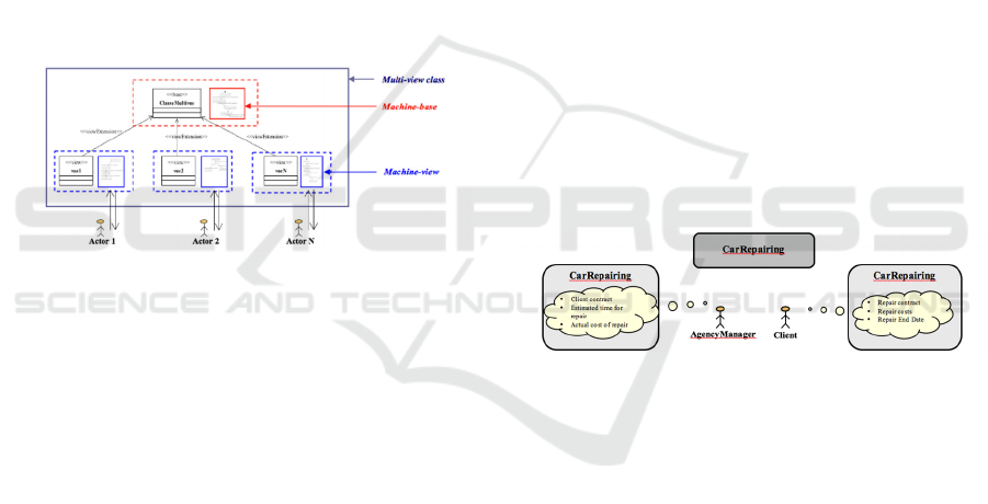
Figure 1 below shows the structure of a multi-view
class. The static system is represented by the
stereotyped data classes "base" and "view". In
contrast the behaviour is represented by the state
machines ("machine-base" and "machine-view")
associated with these classes.
Figure 1: Abstract representation of a multi-view class.
The state machines we propose follow the
UML2.0 specification and are attached either a base
or a view. The base machine defines the overall life
cycle of a multi-view object to be shared by all views.
It consists of states that are relevant to all actors and
transitions between these states. Therefore, the
"machine-base" is abstract and consists of general
phases covering the life cycle of the multi-view
object. Each machine view shares the structure of the
"machine-base" and specialises in it by adding
behaviour that handles queries from the actor
associated with the view. The addition of behaviour
is done in particular by refining the (abstract) states
of the "machine-base" into sub-machines (compound
states UML). We call the multi-view machines the set
formed by a "machine-base" and dependent
machines-view. The consistent operation of the multi-
view machine is achieved by synchronising the
transitions defined within the "machine-base", which
may therefore only be crossed at an equivalent time
by all the machines-view.
We define a multi-view state as the state
representing a multi-view object. It is a state with
several interpretations according to the actors
interacting with the system, defined by the following
sub-states:
A base-state of the "machine-base": an abstract
state that represents a point in the life cycle of
a multi-view object.
A set of view-states constituting the view-
machine: states were resulting from the
refinement of the base state, considering the
viewpoints of system actors.
For example, in Fig. 2, the state of the car
CarRepairing (in the centre of the figure) is a multi-
view state, interpreted differently according to each
type of actor. A mechanic is interested in faults and
repairs, tools needed to perform repairs, and spare
parts. While a workshop manager sees the repair on
the logistics side, that is to say, that he is interested in
the assignments of the tracks, the reservation of the
equipment, the allocation of the spare parts, etc. For a
client, the technical details of a repair are not
necessary; he is more interested in the details of the
repair contract, the costs to be incurred, and the date
of completion of the repairs. The interests of the
agency manager focus on the financial aspect of this
repair, including its actual cost, the estimated time for
completion of the repairs, and the contract to be
drawn up with the client.
Figure 2: Illustration of the CarReprairing Multi-View State
3 VUML APPROACH
VUML (View-based UML) language is a UML
configuration file based on the perspective modelling
method. This profile offers a formalism extending
UML and an approach inspired by that of the
VBOOM (View-Based Object-Oriented
Methodology). In addition to relying on a non-
standard formalism inspired by the Eiffel language,
VBOOM suffered from several limitations, including
the implantation of views by multiple inheritances
and the strong non-determinism in identifying views.
VUML, while aiming at objectives similar to
those of VBOOM, explicitly relies on the UML
standard and introduces a set of concepts and
mechanisms to (i) manage access rights to multi-view
classes, (ii) specialise the multi-view class, (iii)
specify the dependencies between views, (iv) ensure
View-based Modelling: Behaviour Specification based on UML Concept
155
consistency of the model in case of updates, and (v)
administer the views at runtime.
Informally, the critical concepts of VUML are
defined as follows:
Actor: a human or logical entity that interacts
with the system.
Point of view: a view of an actor on the system
(or part of it). A single point of view is
associated with an actor.
View: Modelling entity (static). It corresponds
to applying a point of view on a given entity
(class and by generalisation the whole system).
By simplifying language, we will say that a view is
associated with an actor by considering as implicit the
entity on which the actor’s point of view applies.
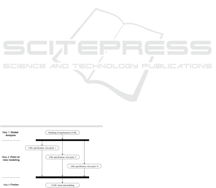
As shown in figure. 3, the VUML approach
consists of three main development phases: a
centralised phase of requirements modelling, a
decentralised phase of system modelling according to
each point of view (using the different UML
diagrams) and finally, a centralised phase of fusion
and modelling producing the VUML class diagram.
Initially, the modelling of the needs is carried out
in the form of use cases; then, for each identified actor
(therefore for each point of view), the scenarios are
specified as well that the associated class diagrams;
the VUML fusion makes it possible to identify the
multi-view classes and to make a global VUML class
diagram.
4 IMPLEMENTATION OF
APPROACH
4.1 Principe
In this approach, we propose to build multi-view ma-
chines complements the structural VUML approach
by adding treatments to end up with the machines
with states: "machine-base" and "machine-view".
Figure 3: General view of the VUML approach.
We describe in this subsection the adaptations we
have made in the VUML approach to take into
account the behavioural aspects of the approach.
4.1.1 Global Behavioural Analysis
The primary role of this phase is the identification of
the "machine-base" of multi-view objects. It consists
of extracting the most relevant stats from the multi-
view object. We obtain the "machine-base" in the
form of an abstract skeleton that describes the
expected behaviour of the multi-view object as a
whole.
This behavioural analysis phase consists of the
following activities:
Identification of reactive multi-view classes,
Identification of potential states for each
reactive multi-view class,
Construction of the general state machine
"machine-base" for each reactive multi-view
class. This machine will be shared so that it is
reused during development by point of view in
the second phase,
Add the name of the machine base in the
application glossary.
4.1.2 Behavioural Analysis/Design by Point
of View
For each actor, we make a mono-view analysis of the
"machine-base" states already developed in the first
phase. We create states of interest for the relevant
actors. At the end of this step, we get the "machine-
view" of all the actors. For each reactive class
identified in the previous phase, the construction
process of a "machine-view" is as follows:
Study of the significance of each state of the
"machine-base" for the relevant actors.
Depending on the importance of the base state
for the treated point of view, the survey of this
state can be concluded by the development of a
sub-machine, thus capturing the specific needs
of the actor.
Create the "machine-view".
If a reactive class is identified during development by
points of view:
Verification of the presence of the associated
"machine-base" in the glossary:
If it exists: recovery and adaptation in
case of need.
Otherwise: development and addition of
the "machine-base" in the glossary.
Development of "machine-view".
BML 2021 - INTERNATIONAL CONFERENCE ON BIG DATA, MODELLING AND MACHINE LEARNING (BML’21)
156
4.1.3 Behavioural Fusion/Synchronisation
The role of this phase is making the correspondence
between the machines-view and the "machine-base".
For each multi-view reactive class, the subsequent
process is as follows:
"machine-base" harmonisation (for example, if
an actor added state, which is not a refinement
of existing states),
Establishment of "machine-view"
communication by synchronization.
We give more details about this synchronisation
process in section (4.4).
4.2 Application on Our Case Study
As already mentioned, the state machines proposed to
describe the behaviour of views follows the UML
standard. Admittedly, UML provides various
concepts for specifying behaviour, all of which have
a graphical notation. However, the semantics is given
to these elements often remain insufficient or
downright indefinite. In fact, the concern to make
UML a modelling standard allowing to
analyse/design any domain led to vague and non-
specific semantics. The syntax we use to express
transitions in developed state machines is derived
from the Omega UML profile. This profile has
relatively rich semantics offering a set of mechanisms
specific to the communication and execution aspects.
We also use the IFx tool associated with this profile.
This tool provides a simulation and validation
environment for Omega UML systems. We used this
tool to simulate and validate our behaviour patterns.
In the remainder of this section, we illustrate applying
the above approach to our case study.
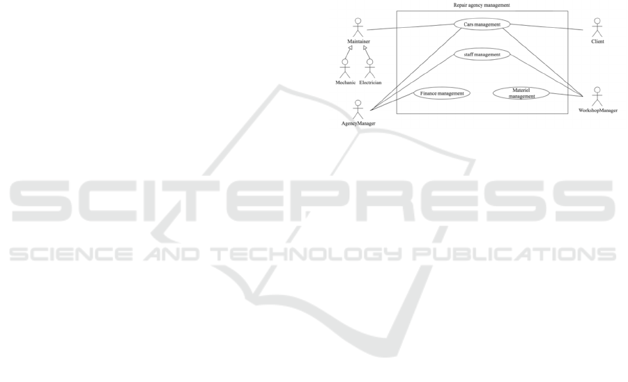
4.2.1 Global Structural Analysis
The first phase of the process is global analysis. It’s a
centralised phase of requirements modelling. The aim
is to identify the needs of the different actors and to
structure them into functional units in the form of use
cases. figure. 4 a provides a general overview of the
functionality to be provided by the system: (1) car
management, (2) personnel management, (3) materiel
management, (4) financial management, and (5)
agency oversight. Each of these features is broken
down into more acceptable functional units showing
the responsibility assigned to each actor. We limited
the study to the following actors: the client, the
agency manager, the workshop manager, and the
maintainer.
For illustrative purposes, we develop here only the
“cars management" functionality (Fig. 4). Managing
the agency’s cars is about managing their registration,
the expertise and repairs made to each of them, and
the final verification tests. A client intervenes in the
case of use "save" by communicating information
concerning his car, participates with the agency
manager in the realisation of contracts of expertise
and repair, and validates the repair by performing the
final test of the proper functioning of his car.
Maintainers are involved in technical phases such as
expertise, repair, and testing. The workshop manager
takes part in the management of the maintenance
tasks to be performed on the car.
Figure 4: General use cases of the "Repair Agency
Management" application
4.2.2 Global Behavioural Analysis
Here we describe the steps of the global behavioural
analysis phase.
a. Identification of Reactive Multi-view Classes
Based on the results of the overall structural analysis
of the case study, we deduce the reactive classes and
the potentially multi-view classes. Indeed, the in-
depth analysis of use cases and the needs of each user
– using sequence and activity diagrams, for example
– makes it possible to identify the classes that can be
multi-viewed and those with reactive behaviour. For
our case study, the classes identified as multi-view are
Car, Expertise, Breakdown, Repair, and Contract. We
consider, for the sake of simplicity, that only the Car
class has reactive behaviour. The other classes are
considered to be data classes (static). The list of
multi-view classes identified in this step, as well as
the classification assigned to each of them in static or
reactive classes, are not final. Other multi-view
classes may appear in the second phase of the
approach during the detailed analysis by point of
view.
b. Identification of Potential States for Each
Reactive Multi-view Class
The potential states for an object are selected to cover
its entire life cycle. For our example, the life cycle of
View-based Modelling: Behaviour Specification based on UML Concept
157
an instance of the Car class is as follows: once the car
breaks down, its owner establishes a contract with the
agency and communicates the information necessary
for the registration of his car. The nominal repair line
followed in the agency starts first by bringing the car
to the garage. Then, the car’s expertise in mechanical
and electrical levels is carried out to detect faults.
Following the results of the expertise, a repair
contract is established. The maintainers then repair
the defects. The last step is the test to check the proper
functioning of the car. The result is a nominal life
cycle encompassing the possible states of a car in the
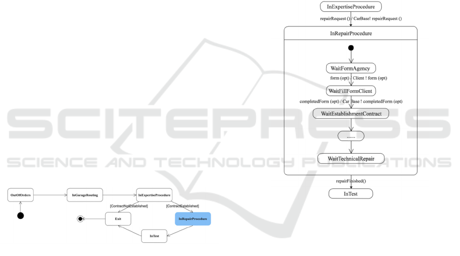
garage. We synthesise these states as follows:
OutOfOrders: initial condition of the car;
InGarageRouting: the condition that represents
the step to bring the car back from where it
broke down to the garage;
InExpertiseProcedure: state representing the
operation of expertise on the car to detect
faults;
InRepairProcedure: After fault detection, the
car begins the repair procedure, which consists
of two essential parts: (i) the negotiation of the
repair contract based on the results of the expert
assessment, and (ii) the technical repair
representing the action of repairing the faults
detected in the assessment phase;
InTest: final step before leaving the garage to
test the proper functioning of the car;
Exit: state representing the end of the life cycle
of the car in the garage.
Figure. 5 shows the base-state machine of Car class.
Figure 5: "machine-base" Associated with the Car Class.
This machine summarises the life cycle of an object
in the system and gives the logical temporal
sequencing of its states. This machine is then added
to the glossary to be shared and reused in the second
phase of the process by the designers.
4.3 Behavioural Analysis/Design by
Perspective
After establishing the structural model according to a
particular point of view (cf. section 4.2.1), the
behavioural specification phase is started according
to the point of view. It consists of a single-view
analysis of the "machine-base" states identified in the
first phase. Each base state can give rise to a sub-
machine, refining it and specialising it to the needs of
the treated point of view. We propose to restrict the
illustration of our example:
Part of the "base-machine". The state we will
detail is InRepairProcedure state during which
the car undergoes a series of actions so that it
regains its normal operating state,
To two actors; the client and the agency
manager.
Client Point of View: Based on the class diagram
developed for the Client Point of View (cf. section
4.2.1), in particular those dealing with the repair and
contract negotiation procedure, we end up with the
part of the SM_Client_Car state machine concerning
the InRepairProcedure state (Fig. 6).
Figure 6: Refinement of the InRepairProcedure Status for
the Client Perspective
The transition in the SM_Client_Car viewport from
the ExpertiseProcedure state to the RepairProcedure
state is triggered by the requested Repair() signal
from the client actor. However, in this step of the
process, the analysis/design by point of view is
carried out in a decentralised manner. As a result, the
SM_Client_Car state machine transmits this signal to
the base machine without worrying about which
objects the signal will be transmitted to. The same
principle is applied when an actor expects a signal
from another entity. If this is the case, the developer
from this point of view assumes that the signal comes
from the "machine-base". That is an example of the
form(opt) signal that triggers the transition between
the WaitFormAgency state and the
WaitFillFormClient state in Fig. 7.
BML 2021 - INTERNATIONAL CONFERENCE ON BIG DATA, MODELLING AND MACHINE LEARNING (BML’21)
158
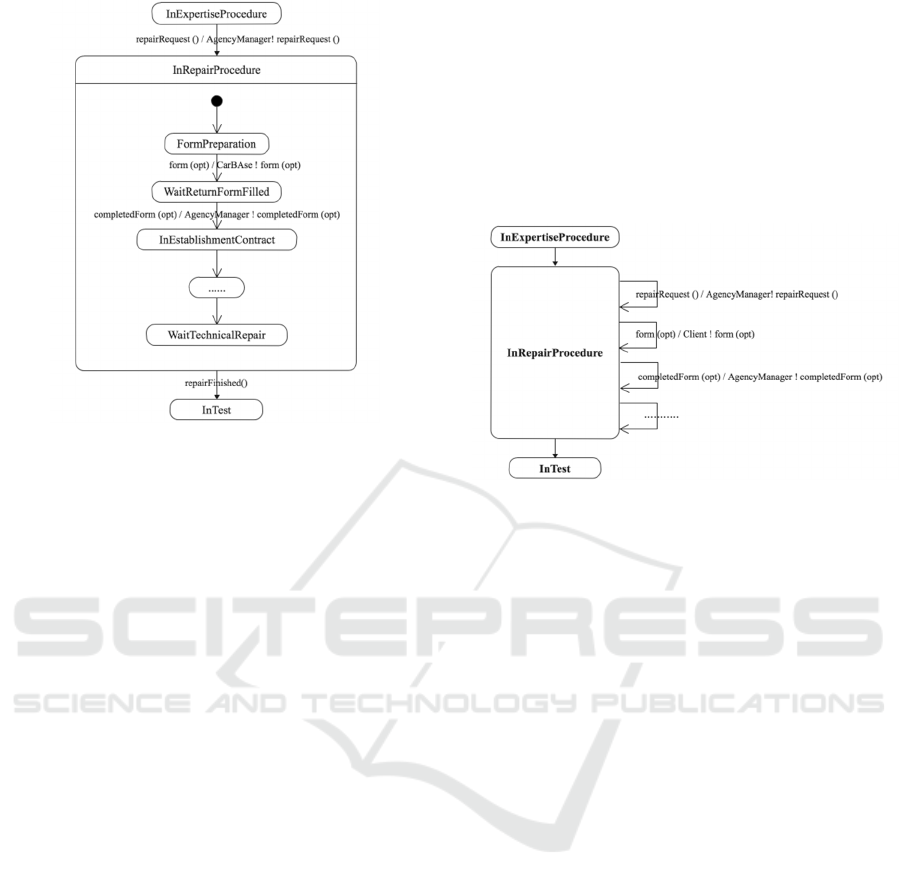
Figure 7: Refinement of the InRepairProcedure Status for
the AgencyManager Perspective
The viewpoint of the AgencyManager: The
refinement of the InRepairProcedure state (figure 7).
The same principle on the centralisation of
communications in the machine base is applied. The
SM_AgencyManager_Car, when it receives the
requested signalRepair() from the "machine-base",
returns it to the agency manager actor. Then, he
prepares a form containing a list of the failures to
repair, as well as the choices that accompany the
repair of each failure. Once the form is ready, the
agency manager sends it to the
SM_Agencymanager_Car (the form(opt) signal
triggers the transition to the
WaitReturnFormCompleted state).
4.4 Behavioural Fusion
The objective of this step is to provide consistency in
the behaviour of multi-view objects by synchronising
the different state machines associated with a multi-
view class. The principle of synchronization is to
ensure communication between the different
"machine-views" through the "machine-base". The
synchronization is to feed the "machine-base" (see
Fig. 5) with messages to create the link between the
machines-sight, that is to say, to make the
correspondence between the requester of the
information and its supplier.
For example, in the "machine-view" of the car
associated with the client’s point of view (see Fig. 6),
the signal repairRequired () was sent to the "machine-
base" (because the developer from the Client point of
view did not know who was going to process this
signal). The Agency Manager "machine-view" (see
Fig. 7) waits for this signal to pass through the
InExpertiseProcedure state to the InRepairProcedure
state. The first synchronization message is shown in
the following (Fig. 8) is for this correspondence. The
synchronization work is continued by following the
same process until the final "machine-base" is
produced.
Figure 8: Adding Synchronization Messages in the
Machine Base for the InRepairProcedure State (Extract).
5 CONCLUSIONS
As we have just seen, this first approach is based
solely on the concepts of UML. The essential result
of this approach is the identification, for a given
multi-view class, of two types of special-condition
machinery attached to either a "base" class or a
"view" class. These state machines, which follow the
specification UML2.0, have the role of capturing the
dynamic behaviour of the instances of the multi-view
class considered. A "machine-view" represents the
life cycle of an object-view, At the same time a
"machine-base" is intended to create coherence and
coordination between the "machines-view" and to
specify the joint behaviour of the actors. The set of a
"machine-base" and dependent machines-view is
called a multi-view machine.
This approach responds to the problem in the
following way: to promote an independent
development in the second phase of the approach, it
was essential that this phase be guided by a model
established a priori; hence the proposal of the concept
of "machine-base". The "machine-base" is developed
during the global modelling phase to specify the
behaviour joint between actors. The latter is
considered as a pattern to be respected when
developing behaviours by points of view. In the
decentralised modelling phase, the machines-view
associated with the objects-view are described
View-based Modelling: Behaviour Specification based on UML Concept
159

separately according to the state of the "machine-
base". In the fusion phase, the composition of the
partial behaviours of the different points of view is
achieved by adding the signal exchanges that allow
the coordination of the machines with states of the
objects-view and the object-base.
However, with this approach, based solely on
UML concepts, when scaling shows limitations:
-concerning the behaviour specification. We have
encountered difficulties in ensuring independence in
the development of views because they can be
strongly intertwined. During a scale-up, this situation
puts the approach at risk and makes it hard to
implement it without altering the development of
other views to collect the missing information. Added
to this; the problem of having to identify multi-view
classes and their "machine-bases" early on in the
global analysis phase. In fact, proposing a state
machine covering the life cycle of an object requires
an in-depth study of the use cases of the multi-view
object. But for a large system, producing such a
machine is not conceivable.
- concerning the composition of the behaviour.
Integrating the separately developed vision machines
may require many modifications and adaptations at
the level of the vision machines and the base machine.
During a scale-up, substantial work must accompany
the compositional operation to ensure the coherence
of the whole.
REFERENCES
Nassar, M., 2005. Analyse/conception par points de vue: le
profil VUML, Doctoral thesis INPT. Toulouse.
Anwar, A., 2009. Formalisation par une approche IDM de
la composition de modèles dans le profil VUML,
Doctoral thesis. Toulouse University. Toulouse.
Kriouile, A., 1995. VBOOM, une méthode orientée objet
d'analyse et de conception par points de vue, Doctoral
thesis at Mohammed V University. Rabat.
Lakhrissi, Y., Ober, I., Coulette, B., Nassar, M., Kriouile,
A., 2007. Vers la notion de machine à états multivue
dans le profil VUML, Workshop WOTIC. Rabat.
Lakhrissi, Y., Coulette, B., Ober, I., Nassar, M., Kriouile,
A., 2008. Démarche VUML statique et dynamique -
Application à une étude de cas, Research report,
IRIT/RR-2008-1-FR, IRIT.
Lakhrissi, Y., Ober, I., Coulette, B., Nassar, M., Kriouile,
A., 2008. Prise en compte des aspects
comportementaux dans la démarche de modélisation de
VUML, ERTSI, associated with the conference
INFORSID, Fontainebleau, Hermès.
Lakhrissi, Y., Anwar, A., Nassar, M., Kriouile, A., 2008.
Composition des machines à états par point de vue dans
VUML, Workshop JIMD'2008, ENSIAS. Rabat
Ober, I., Graf S., 2006. Validating timed UML models by
simulation and verification. International Journal of
Software Tools for Technology Transfer (STTT), vol.
8, N° 2, pp. 128-145, Springer Verlag.
ElMarzouki, N., Lakhrissi, Y., ElMohajir, M., Nikiforova,
O., 2016. Enhancing Conflict Resolution Mechanism
for Automatic Model Composition , Web of Science,
applied computer systems, Riga Technical University,
Riga.
ElMarzouki, N., Lakhrissi, Y., ElMohajir, M., 2016.A
Comparative Study of Structural Model Composition
Methods and Techniques.
ElMarzouki, N., Lakhrissi, Y., Nikiforova, O., ElMohajir,
M., Gusarovs, K., 2017. Behavioral And Structural
Model Composition Techniques: State Of Art And
Research Directions , WSEAS.
ElMarzouki, N., Lakhrissi, Y., ElMohajir, M., Nikiforova,
O., 2017. Toward a Generic Metamodel for Model
Composition Using Model Transformation , Scopus
Procedia Computer Science Elsevier, vol. 104, pp. 564-
57.
ElMarzouki, N., Elaissi, M., Loukili, Y., Lakhrissi, Y.,
ElMohajir, M., Nikiforova, O., 2020. Implementing a
Digital Workspace in the Era of Covid-19 Based on
Model Compositon, Implementing a Digital
Workspace in the Era of Covid-19 Based on Model
Compositon.
Diaw, S., Cisse, M. L., Bah, A., 2017. Using the SPEM 2.0
kind-based extension mechanism to define the
SPEM4MDE metamodel, n Proceedings of ACM
International Conference of Computing for Engineering
and Sciences, Istanbul, Turkish.
Anwar, A., Dakaki, T., Ebersold, S., Coulette, B., Nassar,
M.,2011 A Formal Approach to Model Composition
Applied to VUML, 16th IEEE International Conference
on Engineering of Complex Computer Systems;
ElMarzouki, N., Lakhrissi, Y., ElMohajir, M., Nikiforova,
O., 2017. The Application Of An Aytomatic Model
Composition Prototype On the- Two Hemishpere
Model Driven Approach, IEEE International
Conference on Wireless Technologies, Embedded and
Intelligent Systems (WITS).
Nikiforova, O., ElMarzouki, N., Kuņicina, N.,
Vangheluwe, H., Florin, L., Iacono, M., Al-Ali, R.,
Orue, P., 2016. Several Issues on Composition of
Cyber- Physical Systems Based on Principles of the
Two- Hemisphere Modelling, Scopus In: Proceedings
of the 4th Workshop of the MPM4CPS COST Action,
Poland, Gdańsk.
http://www-if.imag.fr/IFx/
Object Management Group, Inc. Unified Modeling
Language (UML) 2.1.2 Superstructure, 2007.
http://www.omg.org/uml.
BML 2021 - INTERNATIONAL CONFERENCE ON BIG DATA, MODELLING AND MACHINE LEARNING (BML’21)
160
