
Design of a 1 to 4 Wilkinson Divider for 5G Mm-Wave Balanced
Mixer
Abdelhafid ES-SAQY
1
a
, Maryam ABATA
1
, Said MAZER
1
b
, Mohammed FATTAH
2
c
,
Mahmoud MEHDI
3
, Moulhime EL BEKKALI
1
, and Catherine ALGANI
4
1
AIDSES Laboratory, Sidi Mohamed Ben Abdellah University, Fez, Morocco
2
EST, Moulay Ismail University, Meknes, Morocco
3
Microwaves Laboratory, Lebanese University, Beirut, Lebanon
4
ESYCOM Lab, Univ. Gustave Eiffel, CNRS, Le Cnam, Paris, France
Keywords: 5G, balanced mixer, mm-Wave, RF circuit, Wilkinson divider.
Abstract: In this paper, a 4 to 1 Wilkinson divider for a 5G mm-wave balanced mixer is presented. The proposed divider
is studied and designed at 26 GHz using the PH15 technological process of UMS foundry. Simulation results,
presented and discussed in this paper, are in good agreement with theoretical analysis. The 1 to 4 divider
achieves good isolation, low reflection coefficients at all ports, and the minimum number of components. The
divider is compact; it occupies 1.1mm*0.32mm, compared to the conventional one. Therefore, it can be easily
integrated into a 5G mm-wave mixer.
1 INTRODUCTION
Integration promises reduced size, low power
consumption, and reduced manufacturing costs of RF
ICs, while simultaneously increasing system
functionality and performance. However, the design
of high-frequency integrated circuits and systems
presents a significant challenge and requires adapting
new architectures and design methods ((Es-saqy et
al., 2020);(Es-saqy et al., 2021); (Didi et al., 2021);
(Daghouj et al., 2020); (Boumaiz et al., 2019);
(Moutaib et al. 2020); (Fattah et al., 2019);( Abdellaoui
et al., 2019)). The performance of MMIC mixers has
improved significantly with the development of high-
performance transistors: pHEMT ((Huang et al.,
2013); (Zhang et al., 2020)), HEMT (Hamada et al.,
2020), CMOS ((Nam et al., 2020); (Gao et al., 2020)),
and HBT (Song et al., 2020), and with the adaptation
of new single- or double-balanced architectures. In
most of these architectures, the use of a
coupler/divider is indispensable.
In this article, a reduced dimension 1 to 4 power
divider (or coupler) is studied and designed. It’s
inspired by the classic Wilkinson model (Kumar,
a
https://orcid.org/0000-0002-9448-4872
b
https://orcid.org/0000-0003-4812-7708
c
https://orcid.org/0000-0001-6128-9715
2019). However, it has an advantage over the latter,
which has a reduced number of lumped elements to
gain in terms of size. The reduced dimension 1 to 4
divider consists of four-phase shift cells. Comprising
lumped components such as inductors and capacitors.
Thus, we reduce the number of cells by two compared
to the classical configuration, which had six cells (Xie
et al., 2021).
To validate our 1 to 4 power divider design, we
first proceed to matrix analysis. Then, we confirm this
analysis by simulations in ADS software, validate the
divider's design model, and integrate it in any MMIC
circuit, in particular, double balanced mixers.
The paper is organized as follows: matrix analysis
and circuit design are provided in Section 2. Section
3 presents the simulation results and discussion.
Finally, concluding remarks are given in Section 4.
2 DESIGN OF A 1 TO 4
WILKINSON DIVIDER
As shown in Figure 1, the reduced-size 1 to 4 divider
has four phase delay cells with four capacitors, four
Es-Saqy, A., Abata, M., Mazer, S., Fattah, M., Mehdi, M., El Bekkali, M. and Algani, C.
Design of a 1 to 4 Wilkinson Divider for 5G mm-Wave Balanced Mixer.
DOI: 10.5220/0010728500003101
In Proceedings of the 2nd International Conference on Big Data, Modelling and Machine Learning (BML 2021), pages 67-70
ISBN: 978-989-758-559-3
Copyright
c
2022 by SCITEPRESS – Science and Technology Publications, Lda. All rights reserved
67

resistors, and eight inductors. These passive elements,
whose behaviour is very close to reality, belong to the
PH15 technological process from UMS foundry. We
remind that all the ports of the divider are matched
and loaded by Z0 impedances.
2.1 Matrix study of the reduced divider
Consider S
5*5
as the Wilkinson divider matrix:
S
5*5
=
(1)
To simplify this matrix, we are interested in the
particular characteristics of the 1 to 4 divider:
• Impedance matching: to minimize the
reflections present on each port of the 1 to 4
divider, the divider must be matched to the
load Z0 present on each of its five ports.
Thus, all the terms present on the diagonal
of the S
5*5
matrix are zero, i.e.,
S
11
=S
22
=S
33
=S
44
=S
55
=0
• Isolation: the divider must ensure a good
level of isolation between each of these four
output channels, i.e.,
S
23
=S
32
=S
24
=S
42
=S
25
=S
52
=S
34
=S
43
=S
35
=S
53
=S
45
=S
54
=0
• Symmetry: the direct transmission
parameters are identical to the reverse
transmission parameters and are all equal,
i.e., S
21
=S
31
=S
41
=S
51
=S
12
=S
13
=S
14
=S
15
According to these three conditions, the S
5*5
matrix obtained is:
S
5*5
=
(2)
The role of this circuit is the division by four of
the power injected at the input, which results in a
division by √4 of the amplitude. Consequently, the
transmission parameters from the input to the outputs
must have a modulus of a value of 1/2.
On the other hand, a signal injected at the input
passes through four identical -90° phase shift cells.
Therefore, a phase shift of -90° between the injected
signal and the signal recuperated on one of the output
ports. A factor translates this phase shift -j. Therefore,
the matrix S of the 1 to 4 divider becomes:
S
5*5
=
(3)
Thus, by similarity with the classical three-port
Wilkinson (Kiither et al., 1995), we can deduce that:
Z
L
=2*Z
0
We deduce from this that the following equation
can express the values of the passive elements
constituting the circuit:
• For the capacitors:
• For the inductances:
• For the four resistors:
, this value
allows better isolation between all the
accesses.
:2.2 Circuit Design
The electrical circuit is shown in figure 1. The divider
is compact; it occupies 1.1 mm*0.32 mm. In contrast,
the layout of the circuit is presented in figure 2. It
shows that the capacitors have been removed. This is
due to the low value of their capacitance (a few fF at
26 GHz). At this frequency, the parasitic capacitances
of the inductors and the transmission lines have
values in the order of those necessary for the
operation of the coupler.
Figure 1: Reduced power divider circuit.
Figure 2: Reduced power divider Layout.
BML 2021 - INTERNATIONAL CONFERENCE ON BIG DATA, MODELLING AND MACHINE LEARNING (BML’21)
68
3 POST-LAYOUT SIMULATION
To validate our design method, simulations of the
S-parameters of the circuit are carried out under
Agilent's ADS software. These simulations are
performed after the layout design; thus, the parasites
related to the conduction lines are considered.
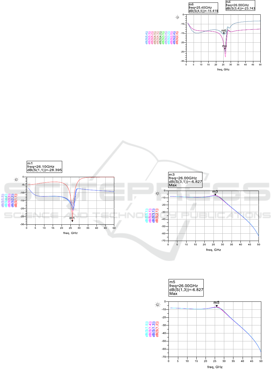
3.1 Reflection coefficients
A first simulation consists of checking the impedance
matching of the five ports at 26 GHz. Figure 3 shows
that at 26 GHz, the reflection coefficients are
minimal. Since this circuit is designed using passive
elements whose behaviour is very close to reality,
these reflection coefficients are very low, less than
-28 dB for S11. Thus the simulation results confirm
our previous matrix analysis.
Figure 3: Reflection coefficients at the input and output of
the four-way power divider.
3.2 Isolations
The second factor to check for validating our analysis
of the 1 to 4 Wilkinson divider is the isolations
between the different output ports. As the circuit has
four output ports, we distinguish twelve terms that
combine all these accesses.
The curves in Figure 4, showing the isolations
between the different output ports of the divider. We
can see that at 26 GHz, the isolation reaches its
maximum level; S-parameters of minimum values
reflect this. In the worst case, the isolation between
ports '4' and '5' exceeds 15 dB, while the isolation
between the other ports is more significant than
23 dB.
Figure 4: Isolation coefficients between outputs of the
reduced four-way power divider.
3.3 Direct transmission coefficients
The direct transmission coefficients of the system are
presented in figure 5, these coefficients reaching a
maximum of -6.8 dB at 26 GHz. This maximum value
confirms the division by four of the power injected at
the input of the circuit and its distribution on all the
circuit outputs.
Figure 5: Direct transmission coefficients (from input to all
outputs) of the reduced four-way power divider.
Figure 6: Inverse transmission coefficients (from outputs to
all input) of the reduced four-way power divider.
Design of a 1 to 4 Wilkinson Divider for 5G mm-Wave Balanced Mixer
69

3.4 Inverse transmission coefficients
The last validation step of our analysis consists of
checking the reciprocity of the 1 to 4 divider circuit.
For this purpose, the inverse transmission coefficients
are shown in figure 6. These curves are identical to
the curves of the direct transmission coefficients,
which fully validates the matrix analysis presented
before.
4 CONCLUSIONS
This paper has presented and designed a 1 to 4
Wilkinson divider for 5G mm-wave mixers. The
divider achieves the performance of good isolation,
low reflection coefficients at all ports, and good
compactness, which make it suitable to be
incorporated into double-balanced mixers operating
in 5G mm-wave around 26 GHz. In our upcoming
work, the circuit studied and designed in this paper
will be integrated into a double-balanced up-
conversion mixer.
REFERENCES
Abdellaoui, M. & Fattah, M. (2019). Characterization of
Ultra Wide Band indoor propagation. IEEE7th
Mediterranean Congress of Telecommunications
(CMT) 2019, pp. 1-4. doi:
10.1109/CMT.2019.8931367.
Boumaiz, M., El Ghazi, M., Bouayad, A., Fattah, M., El
Bekkali, M., and Mazer, M. (2019). The impact of
transmission power on the performance of a WBAN
prone to mutual interference. International Conference
on Systems of Collaboration Big Data, Internet of
Things & Security (SysCoBIoTS), pp. 1-4, doi:
10.1109/SysCoBIoTS48768.2019.9028035
Daghouj, D., et al. (2020). UWB waveform for Automotive
Short Range. International Journal on Engineering on
Engineering Applications (IREA), 8 (4).
Didi, S.E., Halkhams, I., Fattah, M., Balboul, Y., Mazer, S.,
El Bekkali, M., (2021). Design of a Microstrip Antenna
Two-Slot for Fifth Generation Applications Operating
at 27.5 GHz. Springer International Conference on
Digital Technologies and Applications(ICDTA),
Lecture Notes in Networks and Systems, 211. pp 1081-
1089.
Es-saqy, A., Abata, M., Mehdi, M., Fattah, M., Mazer, S.,
El Bekkali, M., &Algani, C. (2021). A 5G mm-wave
compact voltage-controlled oscillator in 0.25 µm
pHEMT technology. International Journal of
Electrical and Computer Engineering (IJECE), 11(2),
1036. https://doi.org/10.11591/ijece.v11i2.pp1036-
1042
Es-Saqy, A., Abata, M., Mehdi, M., Mazer, S., Fattah, M.,
, El Bekkali, M., &Algani, C. (2020). 28 GHz balanced
pHEMT VCO with low phase noise and high output
power performance for 5G mm-wave systems.
International Journal of Electrical and Computer
Engineering, 10 (5), pp. 4623-4630.
FATTAH, M., et al. (2019) .Multi Band OFDM Alliance
Power Line Communication System, Procedia
Computer Science, 151, pp.1034-1039.
Gao, L., Ma, Q., &Rebeiz, G. M. (2020). A 20–44-GHz
Image-Rejection Receiver With >75-dB Image-
Rejection Ratio in 22-nm CMOS FD-SOI for 5G
Applications. IEEE Transactions on Microwave Theory
and Techniques, 68(7), 2823–2832.
https://doi.org/10.1109/TMTT.2020.2979441
Hamada, H., Tsutsumi, T., Matsuzaki, H., Fujimura, T.,
Abdo, I., Okada, K., Song, H.-J., &Nosaka, H. (2020).
300-GHz-Band 120-Gb/s Wireless Front-End Based on
InP-HEMT PAs and Mixers. IEEE Journal of Solid-
State Circuits, 55(9), 2316-2335.
Huang, F.-H., Lin, S.-W., Ke, P.-Y., & Chiu, H.-C. (2013).
A wide bandwidth V-band balanced resistive mixer
with a miniature meandering balun. Microwave and
Optical Technology Letters, 55(3), 547–550.
https://doi.org/10.1002/mop.27371
Kiither, D., Hopf, B., Sporkmann, T., & Wolff, I. (1995).
MMIC Wilkinson Couplers for Frequencies up to 110
GHz. in IEEE MTT-S International Microwave
Symposium.
Kumar, M. (2019). Design of compact Wilkinson power
divider and branch-line coupler using hairpin based
line. International Journal of Electronics and
Communications, 110, 1-10.
Moutaib, M., Fattah, M., Farahoui, Y. (2020). Internet of
things: Energy Consumption and Data Storage",
Procedia Computer Science. 175, pp 609- 614.
Nam, H., Lee, W., Son, J., & Park, J.-D. (2020). A Compact
I/Q Upconversion Chain for a 5G Wireless Transmitter
in 65-nm CMOS Technology. IEEE Microwave and
Wireless Components Letters, 30(3), 284–287.
https://doi.org/10.1109/LMWC.2020.2971100
Song, K., Kim, J., Son, H., Yoo, J., Cho, M., &Rieh, J.-S.
(2020). 300-GHz InP HBT Quadrature VCO with
Integrated Mixer. IEEE Transactions on Terahertz
Science and Technology, 10(4), 419–422.
Xie, B., Wang, C., Kumar, A., Wu, Q., & Zhao, M. (2021).
Ultra-compact wideband dual-mode Wilkinson power
divider based on thin-film integrated passive device
fabrication technology. Journal of Electromagnetic
Waves and Applications, 35(2), 163–175.
https://doi.org/10.1080/09205071.2020.1828185
Zhang, L., Tong, X., Han, J., & Cheng, X. (2020). A 4561
GHZ monolithic microwave integrated circuit
subharmonic mixer incorporating dualband power
divider. Microwave and Optical Technology Letters,
62(9), 2851–2856. https://doi.org/10.1002/mop.32401
BML 2021 - INTERNATIONAL CONFERENCE ON BIG DATA, MODELLING AND MACHINE LEARNING (BML’21)
70
