
Numerical Study of the Drag Reduction and the Electronics
Composites Cooling by using the Three Flat Plates
Youssef Admi
a
, Jaouad Benhamou, El Bachir Lahmer
b
, Mohammed Amine Moussaoui,
Mohammed Jami and Ahmed Mezrhab
Mechanics & Energetics Laboratory, Faculty of Sciences, Mohammed First University, 60000 Oujda, Morocco
moussaoui.amine@gmail.com, amezrhab@yahoo.fr
Keywords: Lattice Boltzmann method, flow control, the drag reduction, heat exchange, flat plates.
Abstract: The objective of this research is to study the flow control allowing the reduction of the aerodynamic drag and
at the same time the cooling of the electronic components. To this end, a numerical study was carried out on
the effect of the length of three parallel flat plates on the control of vortex shedding behind a heated square
block located in a two-dimensional channel at Reynolds number fixe (Re = 150). The numerical approach
used to simulate these physical problems is the lattice Boltzmann method (LBM). The results obtained are
illustrated in terms of velocity contours and isotherms. These results present a reduction of more than 67% of
the drag coefficient for a critical length of the control plates (Lp = 2D). In addition, a large and regular heat
exchange for the same length is observed.
1 INTRODUCTION
Nowadays, the technology of electronic components
has progressed strongly. However, despite this
development, the successive increase in temperature
and the high vortex shedding leads to a decrease in
the operating performance and sometimes to the
breakdown of these electronic components
(processors, high-performance servers, etc.). In order
to avoid these impediments, the protection of the
performance of these electronic systems and the
improvement of their efficiency is the greatest
challenge facing researchers and companies in the
electronics industry (El Omari, Kousksou, and Le
Guer 2011; Ali and Arshad 2017; De Césaro Oliveski,
Krenzinger, and Vielmo 2003; Seyyedi et al. 2012;
Nazari and Ramzani 2014)
(El Omari, Kousksou, and Le Guer 2011)
presented a numerical study on the analysis of a
passive cooling system. They employed various
geometries of enclosures filled with phase change
material (PCM) with enhanced thermal conductivity.
The authors evaluated five geometric shapes that
a
https://orcid.org/ 0000-0003-0920-0618
b
https://orcid.org/ 0000-0001-5435-1429
contained the same volume of PCM while cooling the
same surface. Their calculation results show the
significant effect of changing the geometry. Indeed,
they found a maximum temperature difference of up
to 40°C between two of the enclosures. An enclosure
offset vertically from the cooled surface represented
a better performance. (Seyyedi et al. 2012)applied the
Boltzmann lattice method (LBM) to investigate the
influence of a separator plate and an inclined square
cylinder (with 45°). They used a horizontal channel
filled with air with a blocking ratio (𝛽=0.25) as study
geometry. The effects of the plate and cylinder were
examined on the two-dimensional unsteady laminar
flow and on the heat transfer within the channel. Their
numerical results found that there is an excellent
position for the separator plate. This is demonstrated
by a maximum value of the ratio between the Nusselt
number and the drag coefficient. They also showed
that there are particular points where there is a sharp
jump in drag coefficient and average Nusselt number.
This research presents work aimed at
controlling the flow around electronic systems to
improve their performance and increase their
efficiency, as well as improving the quality of heat
Admi, Y., Benhamou, J., Lahmer, E., Moussaoui, M., Jami, M. and Mezrhab, A.
Numerical Study of the Drag Reduction and the Electronics Composites Cooling by using the Three Flat Plates.
DOI: 10.5220/0010727600003101
In Proceedings of the 2nd International Conference on Big Data, Modelling and Machine Learning (BML 2021), pages 21-26
ISBN: 978-989-758-559-3
Copyright
c
2022 by SCITEPRESS – Science and Technology Publications, Lda. All rights reserved
21
transference around these systems. For this purpose, a
numerical study of the flow around a heated square
block controlled by three flat plates parallels located
in a bi-dimensional channel was performed. The
simulations were carried out by the double multiple
lattice Boltzmann method. The influence of the length
of the control plates on the temporal and average
variation of the drag coefficient and on the heat
exchange was presented.
2
CONFIGURATION DESCRIPTION
AND BOUNDARY CONDITIONS
2.1 Configuration Domain and Initial
Conditions
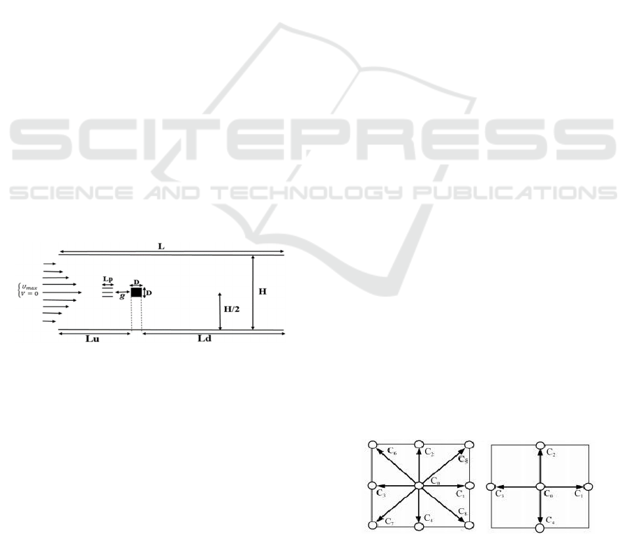
Figure 1 illustrates the geometry employed to study
the flow past a heated square cylinder controlled by
three control partitions placed in a horizontal
bidimensional channel. The square cylinder
positioned in an upstream distance Lu =6D and a
downstream length sufficiently wide Ld = 31D, and a
height H =11D (see Fig. 1) where the "D" represents
the dimension of the square cylinder. The controlling
partitions are arranged successively downstream the
principal square cylinder, having the same length
"Lp" and height "h=0.02D". Moreover, g designates
the gap spacing between the square cylinder and
partitions (see Fig. 1). The fluid entering with a
dimensionless temperature 𝜃
0,5 and the block
is considered heated with a dimensionless
temperature 𝜃
0,5.
Figure 1: The structure of the computational domain.
At the channel input, the flow is created based on
a parabolic velocity profile (u = 1.5 *U
max
(1- (y/H));
v = 0), where U
max
is the maximal entrance velocity,
and y is the vertical dimension from the centerline,
and u and v are the components of velocity vectors.
As well as at the outlet, the parabolic velocity profile
is imposed and the gradients of velocity and pressure
are considered to be zero.
2.2 Boundary Conditions
In LBM, the most well-known type of boundary
conditions in the literature, are the Bounce-Back
boundary conditions(Bouzidi, Firdaouss, and
Lallemand 2001). These conditions are used in the
present work to define the solid walls of the channel.
In the inlet and outlet of the channel, the flow is
completely expanded with a parabolic velocity profile,
so the implementation of the boundary conditions of
Zou and He is the most preferred(Zou and He 1997)
The conditions suggested by (Mezrhab et al.
2010) are used to treat the heat flow boundary
conditions. thus The adiabatic boundary conditions
are applied for the channel walls.
3 NUMERICAL SCHEME
As already mentioned, this paper uses the LB method
as the numerical approach to simulate the physical
phenomenon studied in this work.
Two models are widely used for this method, the
LBM a single relaxation time (BGK-SRT) scheme
(Bhatnagar, Gross, and Krook 1954; Lallemand and
Luo 2000) and the multiple relaxation time (MRT)
scheme (Moussaoui et al. 2021; Admi, Moussaoui,
and Mezrhab 2020; Benhamou et al. 2020;
Moussaoui et al. 2019).
In this paper, the MRT model is used since it is
more stable, precise and presents a good convergence
compared to the SRT model.
3.1 The D2Q9 Model
Thanks to reasons of convergence and compatibility
with the model used in thermic, the D2Q9 model was
used to treat the distribution of the density of fluid
particles. This model is illustrated in figure 1. For
more information, see my previous work(Admi,
Moussaoui, and Mezrhab 2020).
3.2 The D2Q5 Model
For reasons of compatibility and reduction of
calculation time, the D2Q5 model is used to treat the
thermal problem. The motion of the fluid particles, in
this model (D2Q5), is carried out by the discrete
velocities which are given by (Admi et al., 2020):
(a) 𝐷2𝑄9 (b) 𝐷2𝑄5
Figure 2: D2Q9 and D2Q5 LBM schemes.
BML 2021 - INTERNATIONAL CONFERENCE ON BIG DATA, MODELLING AND MACHINE LEARNING (BML’21)
22
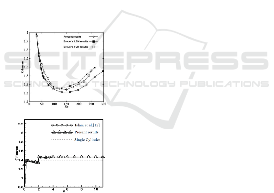
4 CODE VALIDATION
In this work, we have two validation cases with two
different problems. First, we validated our numerical
code with the work of (Breuer et al. 2000) using both
methods: LBM and FVM (finite volume method),
where we examined the flow around a square cylinder
installed inside a horizontal channel with a blocking
ratio of 1/8. Fig. 3-a shows the graph showing the
temporal variation of the drag coefficient as a
function of Reynolds. An agreement existing between
our results and those of Breuer is observed. The small
differences between the two results may be
due to the
mesh size used. Next, we validated our numerical
results with those found numerically by (Islam et al.
2015) or experimentally by (Okajima A 1982) for a
flow around a square obstacle controlled by a single
flat plate (fig. 3-b). Figure 4 shows the variation of
the mean value of the drag coefficient as a function of
the spacing between the square block and the control
plate. A good correspondence is noted between our
results and the reference results.
(a)
(b)
Figure 3: Comparison of our results for the average drag
coefficient with previous works for a single obstacle: (a)
without control partition; (b) with control partition.
5 NUMERICAL RESULTS AND
DISCUSSION
The present section presents the obtained numerical
results of the effect of the length of the three flat
plates on the velocity contours of the flow patterns,
the isotherm contours and on the mean and time drag
coefficient. To avoid the effect of the location
between the plates and the block, a study was carried
out to find the optimal location for which we have a
maximum reduction of the drag coefficient and large
and regular heat exchange. The results obtained in
this study show that the optimal position of the
partitions is g=1.5. In the present work, we have
placed the plates at this critical distance (g = 1.5) and
we have varied their lengths (1D < Lp < 5.5D).
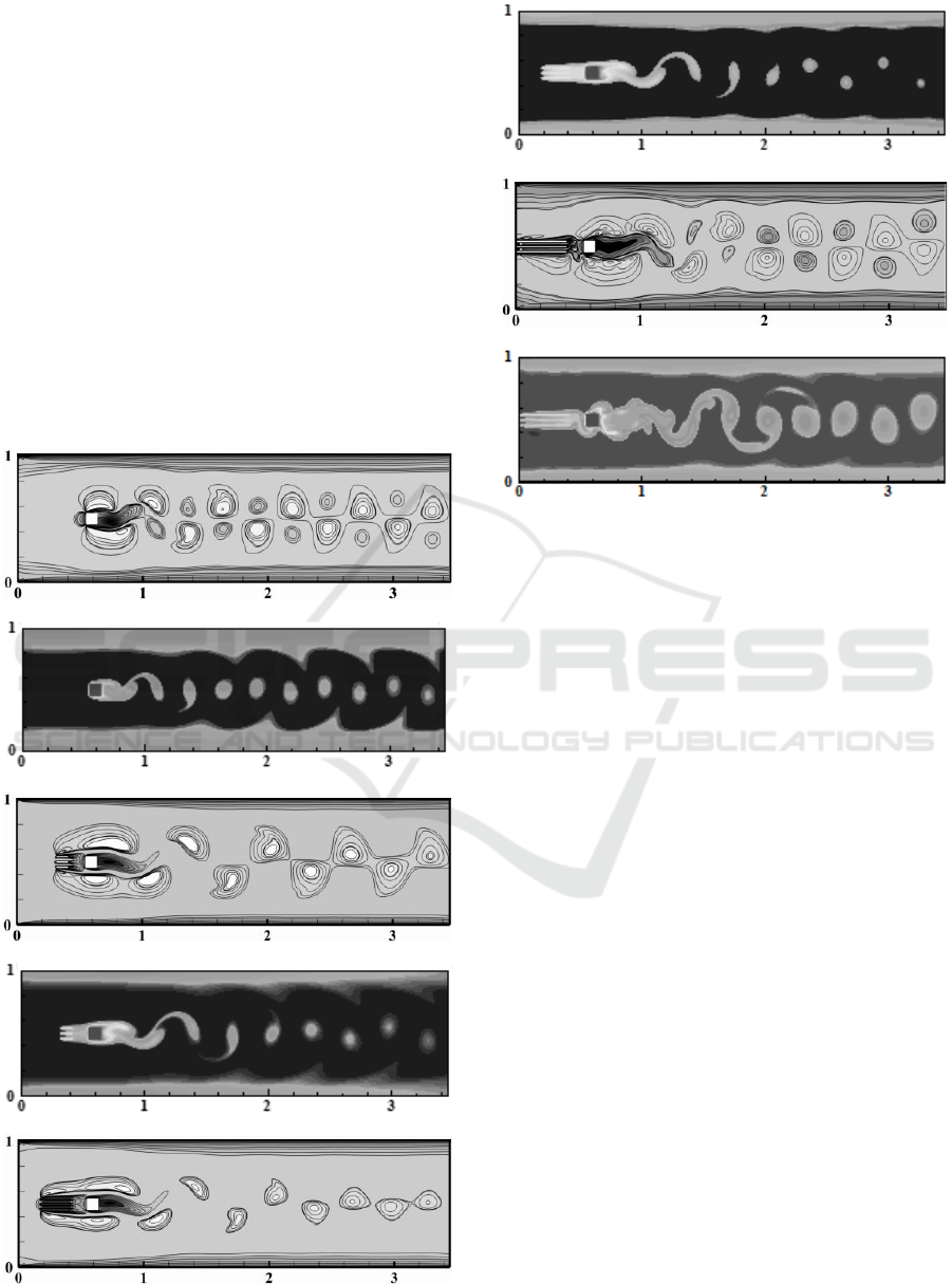
5.1 Streamline Structures and
Isotherms
Figure 5 illustrates the velocity contours (5-a,c,e,g)
and isotherms (5-b,d,f,h) around the square cylinder,
heated and controlled by three parallel flat plates
placed horizontally upstream. In this figure (fig.5), an
alternate Van Karman vortex street is seen in the
wake area downstream of the square cylinder. The
wake can be considered as periodically undulating in
the case where the control partitions are not
implemented (no control case). This undulation
decreases with the increasing plate length until a
critical length Lp=2.5D (Fig.5-e,f). After this critical
length, the wake becomes strongly undulated (see fig.
5-g,h).
Likewise, an alternation of positive and negative
vortices is observed in the uncontrolled case and in
the cases where the plate length exceeds the critical
length, whereas in the cases at or approaching the
critical length only negative vortices are apparent.
Also, the size of detached vortexes behind the square
cylinder decreases with the increasing length until
Lp-critical=2.5D where the vortexes are smaller in
size. Then, this size increases strongly with the
increase of the length of the plates.
We also observe that the number of vortexes
shedding behind the square cylinder in the
uncontrolled case than in the controlled cases. This is
justified by the direct exposure of the frontal surface
of the cylinder to the entering fluid in the uncontrolled
case. Whereas in the case where the three control
plates are inserted, the incoming fluid strikes the
plates firstly before the block. This decreases the
fluidic forces acting on the square cylinder compared
to the uncontrolled case. Similarly, in the case where
the plates are present, part of the front face of the
Numerical Study of the Drag Reduction and the Electronics Composites Cooling by using the Three Flat Plates
23
cylinder is exposed directly to the incoming fluid
while the other part is controlled by these three plates.
Thus, in the case where Lp varies from Lp = 1D to Lp
= 3D (case tested: g=1; 1.3; 1.5; 2; 2.2; 2.5; 2.7; 3) the
length of the control plates is small, the fluid
considers the whole (square cylinder + three
partitions) as one bluffing body. For these lengths,
the shear layers produced by the edges of the
partitions jump up and down behind the square
cylinder. This decreases the number and size of
vortices released behind the square cylinder (the
fluidic forces acting on the square cylinder also
decrease). Whereas, in the case where the length is
large (Lp > 3D), the shear layers are stuck from the
bottom and top surface of the plates and then partially
or completely hit the front face of the square cylinder,
which again increases the size of the vortices
shedding behind the square cylinder.
(a)
(b)
(c)
(d)
(e)
(f)
(g)
(h)
Figure 4: Velocity & Isotherms contours visualisation :
Velocity contours (a, c, e, g);Isotherms contours (b, d, f, h)
5.2 Drag Coefficient
In this section, the effect of the length of the plates on
the time-averaged drag force acting on the square
cylinder. Table 1 gives the average values of the drag
coefficient Cdmean and the length of the control
plates while fixing the spacing between the partitions
and the square cylinder. Figure 5 illustrates the time
variation of the drag coefficient in the case with and
without control plates. From this figure, it can be
noted that the drag coefficient varies periodically and
that the average value of the drag coefficient is
𝐶𝑑𝑚𝑒𝑎𝑛0 1.1. A comparison between Cdmean0
and the average values presented in Table 1 shows
that the drag acting on the cylinder decreases
significantly when the control partitions are
implemented. This decrease (drag reduction) is
caused by changing the flow input that hits the square
cylinder. In this work, the control plates are located
before the cylinder, so the cylinder will be in the wake
of the plates. This will decrease the pressure forces
applied in this wake area, resulting in a decrease in
drag force (also, an increase in lift force).
BML 2021 - INTERNATIONAL CONFERENCE ON BIG DATA, MODELLING AND MACHINE LEARNING (BML’21)
24
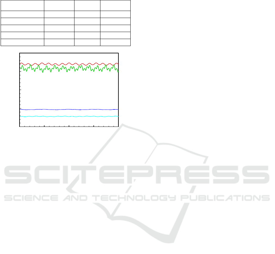
Table1: The average drag coefficient in function of the flat
plates length.
Lp
Cdmean Lp Cdmean
Without control 1.0998 2.2D 0.3905
1D 0.4831 2.5D 0.3892
1.3D 0.4453 3D 0.4078
1.5D 0.4268 4D 0.6948
2D 0.3969 5.5D 1.0384
Figure 5. The temporal drag coefficient visualisation
Similarly, Table 1 shows that the highest Cdmean
value appears for the uncontrolled case, then a
reduction in Cdmean values is observed until it
reaches a minimum in the case where the length of the
plates becomes equal Lp
cr
= 2.5. At this critical
length, an effective vortex suppression was observed.
After this critical length, the average drag coefficient
increases again with increasing plate length. The front
face of the square cylinder is partially or totally
exposed to the shear layers detached by the edges of
the control plates. This increases the pressure forces
applied on the cylinder and consequently increases
the drag force. The optimal length of the control
plates (Lp=2.5) corresponds to a minimum Cdmean
value and a high and even heat exchange. A
maximum reduction of the average drag coefficient
reaches about 64.6% for Lp=2.5D (critical length).
Therefore, in the other cases (Lp varies from 1D to
3D), the incoming fluid considers the control plates
and the cylinder as a single bluff body. This reduces
the fluidic forces applied on the cylinder and the
amplitude of the vortex shedding.
6 CONCLUSIONS
The present research presents a numerical
investigation that had been performed to study the
vortex suppression (drag reduction) and to study the
heat transfer characteristics on a heated square
cylinder placed in a horizontal 2D channel and
controlled by three partitions arranged in parallel
upstream of the square cylinder.
The numerical results obtained show that the drag
acting on the square cylinder reduces in all the cases
studied compared to the uncontrolled case. This
shows the importance and the necessity of flow
control. The maximum reduction of the drag is
observed in the case where the length of the partitions
becomes a critical length Lpcr = 2.5D. At this length,
important and regular heat exchange is observed.
Also, the size of the thermal vortices and the width of
the Von Karman street decreases at this critical
position. Therefore, for beneficial use of the control
partitions, for example, in the cooling of electronic
components, it is preferable to use three parallel
partitions of length Lp = 2.5D placed upstream of the
square cylinder at a critical distance g = 1,5.
REFERENCES
Admi, Y., Moussaoui, M.A., Mezrhab. A., 2020. “Effect of
a Flat Plate on Heat Transfer and Flow Past a Three
Side-by-Side Square Cylinders Using Double MRT-
Lattice Boltzmann Method.” In 2020 IEEE 2nd
International Conference on Electronics, Control,
Optimization and Computer Science, ICECOCS 2020.
Ali, H.M., Adeel, A., 2017. “Experimental Investigation of
N-Eicosane Based Circular Pin-Fin Heat Sinks for
Passive Cooling of Electronic Devices.” International
Journal of Heat and Mass Transfer.
Benhamou, J., Jami, M., Mezrhab, A., Botton, V., Henry,
D., 2020. “Numerical Study of Natural Convection and
Acoustic Waves Using the Lattice Boltzmann Method.”
Heat Transfer.
Bhatnagar, P. L., Gross, E.P., Krook, M., 1954. “A Model
for Collision Processes in Gases. I. Small Amplitude
Processes in Charged and Neutral One-Component
Systems.” Physical Review.
Bouzidi, M., Firdaouss, M., Lallemand, P., 2001.
“Momentum Transfer of a Boltzmann-Lattice Fluid
with Boundaries.” Physics of Fluids.
Breuer, M., Bernsdorf, J., Zeiser, T., Durst, F., 2000.
“Accurate Computations of the Laminar Flow Past a
Square Cylinder Based on Two Different Methods:
Lattice-Boltzmann and Finite-Volume.” International
Journal of Heat and Fluid Flow.
Césaro, O., Rejane, D., Arno K.., Horácio, A. Vielmo.
2003. “Cooling of Cylindrical Vertical Tanks
Submitted to Natural Internal Convection.”
International Journal of Heat and Mass Transfer.
Islam, S. Ul., Rahman, H., Abbasi, W. S., Shahina, T.,
2015. “Lattice Boltzmann Study of Wake Structure and
Force Statistics for Various Gap Spacings Between a
Square Cylinder with a Detached Flat Plate.” Arabian
Journal for Science and Engineering 40 (8): 2169–82.
t
C
d
580000 585000 590000 595000 600000
0.25
0.5
0.75
1
1.25
no control
Lp = 2. 5D
Lp = 5.5D
Lp = 1D
Numerical Study of the Drag Reduction and the Electronics Composites Cooling by using the Three Flat Plates
25

Lallemand, P., Li, S.L., 2000. “Theory of the Lattice
Boltzmann Method: Dispersion, Dissipation, Isotropy,
Galilean Invariance, and Stability.” Physical Review E
- Statistical Physics, Plasmas, Fluids, and Related
Interdisciplinary Topics.
Mezrhab, A., Moussaoui, M.A., Jami, M., Naji, H.,
Bouzidi, M., 2010. “Double MRT Thermal Lattice
Boltzmann Method for Simulating Convective Flows.”
Physics Letters, Section A: General, Atomic and Solid
State Physics.
Moussaoui, M. A., Admi, Y., Lahmer, E.B., Mezrhab, A.,
2021. “Numerical Investigation of Convective Heat
Transfer in Fluid Flow Past a Tandem of Triangular and
Square Cylinders in Channel.” IOP Conference Series:
Materials Science and Engineering.
Moussaoui, M. A., Lahmer, E.B., Admi, Y., Mezrhab, A.,
2019. “Natural Convection Heat Transfer in a Square
Enclosure with an inside Hot Block.” In 2019
International Conference on Wireless Technologies,
Embedded and Intelligent Systems, WITS 2019.
Nazari, M., Ramzani, S., 2014. “Cooling of an Electronic
Board Situated in Various Configurations inside an
Enclosure: Lattice Boltzmann Method.” Meccanica.
Okajima A. 1982. “Strouhal Number of Rectangular
Cylinders.” Journal of Fluid Mechanics.
Omari, K.E., Kousksou, T., Guer, Y. L., 2011. “Impact of
Shape of Container on Natural Convection and Melting
inside Enclosures Used for Passive Cooling of
Electronic Devices.” Applied Thermal Engineering.
Seyyedi, S.M., Bararnia, H., Ganji, D.D., Gorji-Bandpy,
D.D, Soleimani, S., 2012. “Numerical Investigation of
the Effect of a Splitter Plate on Forced Convection in a
Two Dimensional Channel with an Inclined Square
Cylinder.” International Journal of Thermal Sciences.
Zou, Q., He, X., 1997. “On Pressure and Velocity Boundary
Conditions for the Lattice Boltzmann BGK Model.”
Physics of Fluids.
BML 2021 - INTERNATIONAL CONFERENCE ON BIG DATA, MODELLING AND MACHINE LEARNING (BML’21)
26
