
A Modular Autonomous Driving System for Electric Boats based on
Fuzzy Controllers and Q-Learning
Emanuele Ferrandino
a
, Antonino Capillo
b
, Enrico De Santis
c
, Fabio M. F. Mascioli
d
and Antonello Rizzi
e
Department of Information Engineering, Electronics and Telecommunications (DIET), University of Rome “La Sapienza”,
Via Eudossiana 18, 00184 Rome, Italy
Keywords:
Electric Boat, Autonomous Driving System, Finite State Machine, Autopilot, Obstacle Detection, Obstacle
Avoidance, Motion Control, Virtual Anchor, Q-Learning, Fuzzy Controller, Fish Schooling Behavior.
Abstract:
This paper describes the architecture and control design of an autonomous Electric Boat, together with a spe-
cific simulation environment for training and testing the Fuzzy Inference Systems. The boat will be in charge
to exit and enter from harbors, plan and follow a route, avoid obstacles such as other boats, correct its motion,
perform a virtual anchor and switch between these operations autonomously. The boat is equipped with a set of
smart sensors such as sonars, a Global Positioning System, a camera-based vision system and an Inertial Mea-
surement Unit. General navigation rules are respected during the route. We propose an architecture integrating
several Fuzzy Controller-based modular pipelines. Furthermore, we propose a mathematical formalization of
the Fish Schooling Behavior useful for training Fuzzy Controllers through Q-Learning. Our architecture will
soon be implemented on a real boat intended for navigating in inland waters.
1 INTRODUCTION
Advanced driver-assistance systems (ADAS) are elec-
tronic systems used to automate vehicle driving and
parking functions. The progressive integration of the
ADAS is being implemented through 5 levels of au-
tonomous driving. At the fifth level, the degree of au-
tomation and safety of the vehicle is such that the con-
trols for manual driving are absent and there is only
a suitable Human Machine Interface (HMI) to allow
the human to enter a destination. ADAS refer to land
vehicles such as private cars, taxis, buses and so on.
Although autopilot has been a standard for ships since
even before ADAS were born, ADAS-like standards
do not yet exist for the marine industry, as underlined
in (Wang et al., 2020).
From the references (Grigorescu et al., 2020), (Li
et al., 2018a), (Bojarski et al., 2016) and (Xia et al.,
2016) it is highlighted that Deep Learning (DL), Re-
inforcement Learning (RL) and Deep Reinforcement
a
https://orcid.org/0000-0001-6472-6597
b
https://orcid.org/0000-0002-6360-7737
c
https://orcid.org/0000-0003-4915-0723
d
https://orcid.org/0000-0002-3748-5019
e
https://orcid.org/0000-0001-8244-0015
Learning (DRL) are the main techniques for build-
ing Autonomous Driving Systems (ADSs). In (Grig-
orescu et al., 2020) are also shown the two main ap-
proaches to the ADS’s architecture design: i) mod-
ular perception-planning-action pipeline, as well as
the ones shown in (Tsai et al., 2019) and (Li et al.,
2018b); ii) the End2End system, as in (Bojarski et al.,
2016). In the modular pipeline the problem is decom-
posed in sub-tasks, while an End2End system directly
maps the perception space to the motion control space
thanks to Deep Neural Networks (DNNs). It is clear
that, in the face of a more complex architecture, mod-
ular pipelines can offer awareness of the specific mo-
tivations behind certain maneuvers undertaken by the
ADS. On the other hand, End2End systems are dif-
ficult to interpret but they offer grater reliability and
speed of execution. Even considering a modular sys-
tem made up of many modules, the amount of data
necessary to train all the modules is clearly lower
than that necessary to train an End2End system, as
this is trained with an enormous amount of real im-
ages. Furthermore, although in modular systems real
data (such as images) are still needed to train, for ex-
ample, the object detection and recognition system,
most of the remaining modules work at more abstract
levels and therefore with data that can easily be sim-
Ferrandino, E., Capillo, A., De Santis, E., Mascioli, F. and Rizzi, A.
A Modular Autonomous Driving System for Electric Boats based on Fuzzy Controllers and Q-Learning.
DOI: 10.5220/0010678100003063
In Proceedings of the 13th International Joint Conference on Computational Intelligence (IJCCI 2021), pages 185-195
ISBN: 978-989-758-534-0; ISSN: 2184-3236
Copyright © 2023 by SCITEPRESS – Science and Technology Publications, Lda. Under CC license (CC BY-NC-ND 4.0)
185

ulated. This offers an advantage to modular systems
also in terms of the ease of tractability of the problem.
Inside modular pipeline-based systems, Neural Net-
works (NNs) (Bianchi et al., 2015) and Fuzzy Con-
trollers (FCs) (De Santis et al., 2018) are still used to
solve sub-tasks. Sub-tasks are route planning, obsta-
cle avoidance, goal seeking, motion control and so on.
DNNs, and in particular Convolutional Neural Net-
works (CNNs), represent the standard for the object
detection and recognition task, as underlined in (Li
et al., 2018b) and (Prabhakar et al., 2017).
Ships using Global Positioning System (GPS) and
digital compass-based adaptive autopilot are becom-
ing more and more frequent (in particular for mer-
chant ships), as described in (Sakagami and Terao,
2012), (Wang et al., 2020), (Chu et al., 2008) and
(Weng et al., 2018). The AI techniques have also
been used for other aspects of navigation, such as per-
forming anti-collision maneuvers and route planning
autonomously. Both the literature on route planning
for Unmanned Water Vehicles (UWVs), as in (Plumet
et al., 2015), (Liang et al., 2018), and (Kobayashi
et al., 2014) and for Autonomous Mobile Robots
(AMRs), as in (Zhuang et al., 2002), report the use
of several techniques such as the Potential Fields with
the Rolling Time Horizon method, RL and tailored
procedures optimized by means of Swarm Intelli-
gence. In object avoidance-collision tasks, the only
example applied to a vessel is reported in (Son and
Kim, 2018). On the other hand, much literature on
AMR, such as (Boujelben et al., 2013), (Liu et al.,
2006), (Boujelben et al., 2017) and (He et al., 2008),
has revealed that the most frequent approach adopted
for this task is the Fuzzy Logic (FL). Within the
framework of a FC, several learning and optimization
methods are mentioned: Genetic Algorithms, NNs,
RL and so on.
One of the most interesting works available in the
technical literature on Autonomous Ships is (Elkins
et al., 2010), which describes the AMN (Autonomous
Maritime Navigation) project based on CARACaS
and a wide range of sensors. The CARACaS system
is based on the state of the art of robotics techniques
in which a multi-engines HW is supervised by a Fi-
nite State Machine (FSM). About this, we believe that
some HW dedicated to AI currently available on the
market are also suitable for the realization of complex
modular architectures and to make the latter competi-
tive with End2End systems based on DL.
In this work, our control architecture for an au-
tonomous Electric Boat for inland waters is presented.
The design aims at the level 4 of autonomous driv-
ing (according to ADAS) and to the automation of the
boat operations. The commander of the boat will just
have to enter a destination through a HMI. The boat
will be able to autonomously exit from the harbor or
get away from a dockside. So, it will calculate a route
and pilot the boat to its destination, also taking care to
avoid fixed and mobile obstacles (such as boats, buoys
and swimmers). Near the destination, the boat will be
able to autonomously enter the harbor or approach the
dockside.
Currently, the development has produced a simu-
lator in MATLAB
R
environment, in which the phys-
ical and control models of the boat are included and
they are intended for the automata training.
The proposed architecture and methodology will
soon be implemented on a real Electric Boat using
Nvidia’s development kits, such as the Jetson AGX
Xavier
1
. The code produced from the training virtual
environment will be ported on the dedicated HW. It is
designed for performing in parallel several inferenc-
ing processes and for executing algorithms.
The boat, named Valentino III (see the concept
rendering of the boat in Figure 1), is conceived to
be used in the future for touristic purposes – within
the LIFE for Silver Coast’ (LSC) European Project
(LIFE16 ENV/IT/000337) managed by the ”Pole for
Sustainable Mobility” (Po.Mo.S) located in Cisterna
di Latina (Italy) – and it is designed to be sustain-
able in term of environmental impact. In fact, it is a
full electric boat organized as a microgrid (De San-
tis et al., 2013; De Santis et al., 2015; Leonori et al.,
2017), equipped with solar panels, batteries for en-
ergy storage and an intelligent Energy Management
System. Details can be found in (Ferrandino. et al.,
2020). Hence, the approach adopted within the design
philosophy is the systemic one, in that the entire Elec-
tric Boat is conceived as an adaptive complex system
(De Santis et al., 2017) interacting with another com-
plex system, that is the surrounding environment. In
other words, within the design idea cohabit both the
classical engineering ”divide et impera” paradigm and
the holistic point of view, where each intelligent mod-
ule is at the same time an element of a vertical hier-
archy but also part of a horizontal organization. This
vision leads to specific codesign procedures and pre-
cise design choices. The latter constitute the main ob-
jective of the present work.
The rest of the paper is organized as follows.
Section 2 describes the architecture we propose and
its sub-systems. Section 3 illustrates the Fuzzy Q-
Learning (FQL) method that is intended for the learn-
ing of FCs and our mathematical formalization of the
fish schooling behavior, which is used as reward func-
1
See description at https://www.nvidia.com/it-
it/autonomous-machines/embedded-systems/jetson-agx-
xavier/
FCTA 2021 - 13th International Conference on Fuzzy Computation Theory and Applications
186
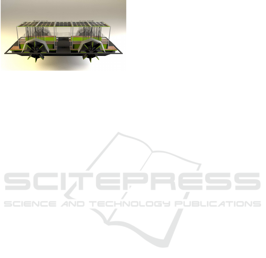
Figure 1: The Solar-hybrid Electric Boat, Valentino III.
tion. Section 4 details the developed simulator. Sec-
tion 5 reports conclusions and future developments.
2 PROPOSED AUTONOMOUS
DRIVING SYSTEM
ARCHITECTURE
The architecture described in the present work will be
implemented on an electrically propelled boat. The
original propulsion system (detailed in the Subsection
2.1) is aimed to make the boat as stable and govern-
able as possible. The autonomous Electric Boat was
designed to improve the sustainability of a local trans-
port system and protect the environment, while also
performing environmental measurements and analy-
sis.
In most of the literature, it appears that both mod-
ular pipeline-based and End2End systems perform
only a sub-set of the functions that make autonomous
a vehicle or robot. For example, they control the
vehicle’s steering, but not the cruising speed, or the
emergency braking or parking functions. For this rea-
son we adopt a suitable complex architecture, illus-
trated in the Figure 2, that ensembles several mod-
ular pipelines in a supervised machine (similarly to
the AMN project mentioned in (Elkins et al., 2010)).
Each pipeline contains a FC-based planning-action
block and executes a specific function of the boat. We
can also identify several levels in the proposed archi-
tecture: the perception level (in grey); the supervision
level (in red); the driving level (in black); the motion
control level (in white).
The supervision level consists of a Supervisor, a
HMI and a FSM. The Supervisor block collects the
signals from the perception level and converts them
into the inputs of the FSM. The FSM also receives in-
puts from the HMI. The driving level consists of man-
ual controls and four modular pipelines: i) the navi-
gation pipeline composed by a single block, i.e. the
Autopilot; ii) the obstacle avoidance pipeline com-
posed by an Obstacle Detection System and an Ob-
stacle Avoidance Controller; iii) the harbor exiting
pipeline composed by a single block, i.e. the Exiting
Controller; iv) the harbor entering pipeline composed
by the Entering Controller. Finally, the motion con-
trol level consists of a single block named Propulsion
System Controller.
The four modular pipelines and manual controls
provide motion control signals which converge into
a multiplexer. Each input of the multiplexer corre-
sponds to a FSM’s state. In other words, the FSM se-
lects the output of the multiplexer by its current state.
The FSM has six states and its transition diagram is
shown in Figure 3.
The initial state is the Virtual Anchor state. In this
state no pipeline works and the motion control signals
are null to perform a virtual anchor, i.e. an anchor
without any physical support. In fact, if we supply
null control signals at the motion control level this
will correct the error on the desired motion, which
is mainly produced by surface water currents or wind.
Note that any state of the FSM can change to the Man-
ual Drive state (in red). The transition to this state
occurs when the commander enters the manual drive
request into the HMI. From the Manual Drive state
the only transition allowed is towards the initial state
(always on explicit request). The FSM jumps from
the initial state to the Exiting state when the comman-
der enters a destination in the HMI. From the latter
it is possible to switch to the Navigation state if the
sonar no longer detects the presence of docks. From
the Navigation state, the FSM switches to the Avoid
state if an obstacle is detected or to the Enter state if
any dockside is detected and the destination is near.
At the end of the operations, the FSM returns from
the Avoid state to the Navigation state and from the
Entry state the FSM returns to the initial state.
Thanks to the FSM the boat is fully auto-
mated. Each state corresponds to a specific process-
ing pipeline. If in the future it will be necessary to
integrate a new function (which can be translated into
motion control signals), it will be sufficient to add a
state in the FSM and the corresponding pipeline.
2.1 Propulsion System and
Environment
The boat’s original propulsion system has been de-
signed in such a way that it gives high maneuverabil-
ity while causing minimal impact on the environment.
It is inspired by the propulsion system of a quad-
copter, in which four independent propellers give 6
degrees of freedom (DOF), but also from a ferry boat,
A Modular Autonomous Driving System for Electric Boats based on Fuzzy Controllers and Q-Learning
187
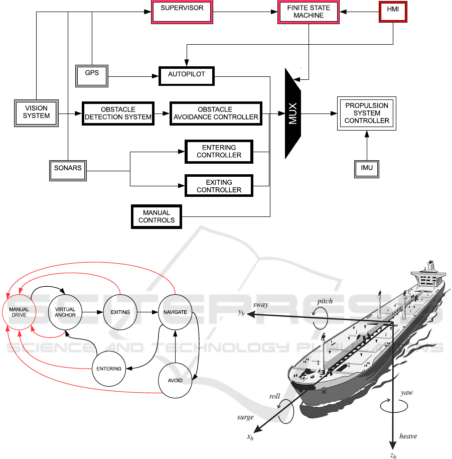
Figure 2: Proposed control architecture.
Figure 3: Transition diagram of the FSM.
in which the paddle wheel and its low rotation speed
causes little or no damage to seabed and fishes. The
Figure 4, obtained from (Fossen, 2021), illustrates the
motion of the boat in 6 DOF.
The propulsion system of our boat consists of four
paddle wheels placed at the corners of a rectangular
frame (see Figure 1). To determine the effective DOF
of the propulsion system, the screw model is adopted
to describe a paddle wheel with non-zero pitch an-
gle. A screw generates a triple of forces (see Fig-
ure 5) which can be directly related to the system of
coordinates presented in Figure 4. Specifically, the
tangential force, F
t
, is related to the surge; the radial
force, F
r
, is related to the heave; the axial force, F
a
, is
related to the sway. Therefore, the presented propul-
sion system allows controlling surge, sway, yaw, pitch
Figure 4: Motion of the boat in 6 degree of freedom (Fos-
sen, 2021).
and roll speeds of the boat. In fact, the control of
the heave speed is excluded for each floating struc-
tures. This propulsion system configuration provides
the boat with 5 DOF. From simple considerations it
is clear that this configuration involves considerable
inefficiencies in energy terms. On the other hand, a
configuration with zero pitch angles provides only 4
DOF (surge, yaw, pitch and roll) reducing the maneu-
verability of the boat. Sway speed control can be very
useful during operations that take place in confined
spaces, such as inside an harbor or near a dockside,
FCTA 2021 - 13th International Conference on Fuzzy Computation Theory and Applications
188

and to perform the virtual anchor. Therefore, the best
configuration is the one with adjustable pitch angle.
Figure 5: Screw model used for paddle wheels with non-
zero pitch angle.
The paddle wheels with adjustable pitch angles
define the following mapping between the input space
and the output space of the Propulsion System Con-
troller:
v
surge
,v
sway
,ω
yaw
,ω
pitch
,ω
roll
7→
7→ ω
1
,ω
2
,ω
3
,ω
4
,ψ
1
,ψ
2
,ψ
3
,ψ
4
(1)
where v
surge
and v
sway
are the surge and sway speeds,
respectively; ω
yaw
, ω
pitch
and ω
roll
are the boat’s yaw,
pitch and roll speeds, respectively; ω
i
and ψ
i
, for
i = 1,...,4, are the paddle wheels’ rotation speeds and
pitch angles, respectively. Note that the problem is
under-defined and than it is not possible to solve it
in closed form. For this reason, we propose a feed-
forward NN-based Direct Controller (DC) architec-
ture trained by a backpropagation (BP) algorithm for
dynamically mapping the motion control signals to
the paddle wheels’ rotation speeds and pitch angles.
Backpropagation signals are the effective surge, sway,
yaw, pitch and roll of the boat, provided by the Iner-
tial Measurement Unit (IMU). In this way, small per-
turbations (such as surface currents in inland waters)
will also be compensated.
Figure 6: NN-based Direct Control architecture.
The NN-based DC architecture is illustrated in
Figure 6 (Siddique and Adeli, 2013). The controller
is a three-layered network in which sigmoid activation
functions are used. The plant represents the complex
environment. The controller parameters are updated
on the basis of the BP algorithm, but in this particu-
lar architecture the error is calculated on the output of
the plant and not on the output of the network itself
(as is done in the classic BP algorithm). The error
is backpropagated through the plant at each time step
in order to update the controller parameters. To do
this it is necessary to know the Jacobian of the plant
or its approximation with the signs of the elements of
the Jacobian. Fortunately, in our case the Jacobian of
the plant is known. With reference to the Figure 6,
the r signal corresponds to the motion control signals,
the u signal corresponds to the signals that control the
Propulsion System, and the y signal corresponds to
the measurements made by the IMU. The goal of NN
training is to generate the signals u such that the error,
e = r − y, tends to 0. This architecture offers the ad-
vantage of being able to carry out a continuous online
training. In this way, the controller can adapt to the
constant changes of a chaotic environment. Further-
more, the DC architecture has been shown to be par-
ticularly effective in solving unknown nonlinear and
non affine problems. On the other hand, the DC ar-
chitecture causes an instability of the plant response
at the beginning of the training. Also for this reason,
the preliminary training steps are performed in a vir-
tual environment.
2.2 Autopiloting
The navigation pipeline is responsible for generat-
ing a route and piloting the boat until its destination.
Since in inland waters waves or deep currents are ab-
sent and surface currents are weak and infrequent, the
navigation pipeline does not take into account certain
phenomena to replan the route. For this reason, it is
composed of a single block, i.e. the Autopilot, which
is designed with classical methodologies. The inputs
of the Autopilot block are the current position (pro-
vided by the GPS) and the goal position (provided by
the HMI). The outputs of the Autopilot are the mo-
tion control signals, v
surge
and ω
yaw
. The other motion
control signals are nulls in order to compensate sway,
pitch and roll of the boat.
2.3 Entering and Exiting from Harbors
Entry and exit from harbors is enabled by a sonar ar-
ray arranged around the boat. Thanks to Sensor Fu-
sion techniques it is possible to determine the pres-
ence and distance of docks from each of the four sides
of the rectangular profile of the boat. This information
A Modular Autonomous Driving System for Electric Boats based on Fuzzy Controllers and Q-Learning
189

is used by the two blocks related to the Entering and
Exiting pipelines to process the maneuvers needed to
move away and approach, respectively, to the docks
without collisions. For these tasks, the blocks return
three motion control signals, v
surge
, v
sway
and ω
yaw
,
because we want to exploit the boat’s maximum ma-
neuverability. Hence, ω
pitch
and ω
roll
are nulls. In
the simulator the distances from docks or natural edge
for each side of the boat is computed thanks an occu-
pancy map. In fact, for each region of the current map,
the position of each object is well known.
Each of the two systems is designed as a Mam-
dani FC with centroid defuzzification method. A set
of rules suitable for synthesizing these two systems is
not known a priori. For this reason, it was decided to
use the FQL method to train the FC. Assuming that
the term set of each input and output signal has three
membership functions (MFs) – two boundary trape-
zoidal functions, and a central triangular function –
since the FC has four inputs, its initial rule base has
81 rules. Such term set is shown in Figure 7.
0 0.1 0.2 0.3 0.4 0.5 0.6 0.7 0.8 0.9 1
FRONTAL DISTANCE
0
0.2
0.4
0.6
0.8
1
DEGREE OF MEMBERSHIP
NEAR MIDDLE FAR
Figure 7: Fuzzy input term set for a distance variable.
2.4 Obstacle Avoiding
The obstacle avoidance is enabled by a camera-
based vision system, which feeds images to a CNN-
based Obstacle Detection System. The CNN will
be separately developed via the Python programming
language and trained to detect boats, as done in
(Akiyama et al., 2018), and other common objects in
the marine environment. The image dataset will con-
sist of the images collected by the Valentino III itself
in a real-world environment. An obstacle detection
flag is passed to the FSM in order to autonomously
switch to and from the Avoid state. In future devel-
opments, the Detection System will be merged with
a Classification System (generating a multi-output
CNN), in order to manage each obstacle class differ-
ently. An obstacle track is given to the Fuzzy Obstacle
Avoidance Controller which must compute a suitable
maneuver to deviate from the collision route. The Ob-
stacle Avoidance Controller returns the motion con-
trol signals, v
surge
and ω
yaw
. We exclude the check
of v
sway
so that the avoidance maneuvers comply with
the general navigation rules. Therefore, v
sway
, ω
pitch
and ω
roll
are nulls.
The Obstacle Avoidance Controller is designed
as a Mamdani FC with the centroid defuzzification
method. It is possible to translate knowledge ex-
pressed in human language into Mamdani rules more
easily than into other fuzzy rules. In the nautical field,
the general rules for navigation must be well known to
those who have to command a boat. They correspond
to rules 4-19 of (U.S.C.G., 2017), a set of precedences
and maneuvers that express the behavior that a boat
must assume when it encounters other boats. Our ap-
proach to the rule base design consists of translating
the rules 4-19 into Mamdani rules in order to set up
the consequents of each rule. In addition, the FC can
be further improved by the FQL method, which will
be applied to the consequent part only.
The inputs of the FC are three angle, specifically:
i) the current orientation of the boat; ii) the angle be-
tween the current orientation and the segment joining
the current position of the boat to the obstacle posi-
tion; iii) the current orientation of the obstacle. These
measures are sufficient to perform a suitable maneu-
ver given a specific scenario and to avoid the obsta-
cle. Additional information, such as size, speed and
acceleration of the obstacle could be considered. In
order to estimate these quantities, a possible solution
consists adopting a binocular vision system (i.e. com-
posed of two parallel cameras, as in (Ma et al., 2019))
as done in (Li et al., 2012). In this case it will also
be necessary to adopt Sensor Fusion techniques and a
second Object Detection System or to provide images
coming from the two cameras alternately to the same
Object Detection System.
Assuming the FC’s input and output term sets
have five triangular MFs, since the FC has three in-
puts, its rule base consists of 125 rules. Such term set,
shown in Figure 8, is customized for the input vari-
ables which are angles. Note that the five MFs repre-
sent four quadrant centered in −π (or equivalently, π),
−π/2, 0 and π/2. A fuzzy rule system is robust to the
uncertainty present in the input space and, at the same
time, makes the output smoother than a crisp rule sys-
tem. A system of crisp rules was used as a benchmark
in order to evaluate the improvement introduced pri-
marily by the fuzzy logic and secondary by the FQL
method.
FCTA 2021 - 13th International Conference on Fuzzy Computation Theory and Applications
190

0 0.1 0.2 0.3 0.4 0.5 0.6 0.7 0.8 0.9 1
DIRECTION
0
0.2
0.4
0.6
0.8
1
DEGREE OF MEMBERSHIP
NEG PI NEG HALF PI ZERO HALF PI PI
Figure 8: Fuzzy input term set for an angle variable.
3 FUZZY Q-LEARNING
In most of the recent technical literature, the FQL is
the main approach for the autonomous navigation of
robots and drones. In (Sharma, 2014) is designed
a FQL controller to implement an UAV’s autopilot.
In (Duan and Xin-Hexu, 2005), (Glorennec, 1996),
(Hong et al., 2017) and (Pambudi et al., 2019) are
designed FQL controllers for AMRs’ navigation sys-
tems. In (Cherroun and Boumehraz, 2012) a FQL
method teaches the fuzzy controller several AMR’s
behaviors, such as goal seeking, obstacle avoidance
and wall following. In (Zhuang et al., 2002) a RL
method and fuzzy states were used to teach an AMR
to plan a route.
The FQL method is a generalization of RL that
allows speeding up the learning and managing con-
tinuous state space problems. It involves training the
consequent part of fuzzy rules on the basis of the so-
called Q-values by using a FQL controller that is ap-
plied to the FC, with the aim of working together and
continuously. Furthermore, the FQL method includes
the deletion and cooperation of the fuzzy rules. If
the truth-value of a rule is never higher than a cer-
tain threshold, this rule is removed. The FQL con-
troller selects an action u
i
from a set U for each out-
put of each rule i on the basis of the related parameter
q(i,u
i
). Usually, the optimal action corresponds to
the one with the higher value for the q parameter. On
the other hand, it is sometimes necessary to try new
actions to improve performance. In order to perform
this task, the exploration/exploitation policy (EEP) is
often used with the FQL method. The action selected
adopting the EEP, u
EEP
i
for the rule i, produces a tran-
siction of the state of the FC from x
k
to x
k+1
. From
this transition, and in general from past experience, a
reward r is calculated a posteriori and then it is used to
update the Q-value related to the inferred action. The
Q-value, Q, as function of the state x
k
and the action
u(x
k
), is given by the following expression:
Q(x
k
,u(x
k
)) =
∑
N
i=1
α
i
(x
k
)q(i,u
EEP
i
)
∑
N
i=1
α
i
(x
k
)
(2)
where N is the number of fuzzy rules and α
i
(x
k
) is
the truth-value of the rule i for the state x
k
, which is
obtained by the antecedent part of the FC. The ∆Q
quantity represents the approximation error for the
Q-value and it is computed as ∆Q = r + γV (x
k+1
) −
Q(x
k
,u(x
k
)). The last expression contains the reward
r, while V (x
k+1
) represents the global target value for
the Q-values at the next time step and γ ∈ [0, 1) is the
discount factor (FQL hyper-parameter). Finally, the
q values are updated according to the following for-
mula:
q(i,u
EEP
i
) ← q(i,u
EEP
i
) + η∆Q
α
i
(x
k
)
∑
N
i=1
α
i
(x
k
)
(3)
where η is the learning rate (FQL hyper-parameter).
We will apply this FQL method to the FCs illus-
trated in the Subsections 2.3 and 2.4. In a Mamdani
FC, actions are represented by MFs in output term
sets. The FC output is obtained with the centroid
defuzzification method so that the existing rules co-
operate. The reward value must be computed by a
reward function (customized for the present applica-
tion), which is illustrated in the following Subsection.
3.1 Fish Schooling Behavior Inspired
Reward Function
The fish schooling behavior describes the social be-
havior of fishes moving in schools. It has inspired sev-
eral engineers in the development of techniques useful
to study fishes themselves (as reported in (Brehmer
et al., 2013) and (Labuguen et al., 2012)), to make a
virtual reality application more realistic (as in (Fuji-
wara et al., 2012)), to create realistic robot fishes as
described in (Swain et al., 2012), but also to create in-
telligent transport systems (as in (Lai and Qu, 2011))
and search algorithms (as in (Aguercif et al., 2017)
and (Cai and Sun, 2017)). However, the fish school-
ing behavior consists of three principles, which are
described in the introduction of (Siddique and Adeli,
2013), that are:
• Attraction - the mutual attraction between the
fishes in a school and between the school and a
common goal.
• Repulsion - the mutual repulsion between fishes
in a school, which allows each fish having enough
space to move, and repulsion of the school to com-
mon dangers.
A Modular Autonomous Driving System for Electric Boats based on Fuzzy Controllers and Q-Learning
191

• Alignment - the mutual alignment between fishes
in a school and the alignment of the school to a
common direction, which allows it following a
current, for example.
Since the three principles correspond to the appro-
priate behaviors of each fish in a school, they can be
used in a single-agent system as well as in a multi-
agent system. Here the three principles have been ap-
plied to a single agent, the boat, and have been rewrit-
ten, according to the present application, as the at-
traction-repulsion-alignment between the boat and a
dockside, an obstacle or a surface water current. The
fish schooling behavior is here formalized in a three-
term convex function, that is:
r = a f
att
+ b f
rep
+ c f
ali
(4)
where a + b + c = 1 and the functions f
att
, f
rep
and
f
ali
can be designed as piecewise defined functions,
such as the following one:
f =
(
t
2
s
2
for t ∈ [0,s)
1 for t ∈ [s,1]
(5)
where s is the threshold for the state t, which repre-
sents a normalized distance.
4 SIMULATOR
The simulator, which was developed in MATLAB
R
environment, is organized in three layers: i) the water
layer, in which the hydrodynamic laws are applied to
boats; ii) the docks layer, in which a dockside can be
alone or more docks will form a harbor; iii) the boats
layer, which keeps track of the orientation and posi-
tion of each boat over the time. The layers can be used
together, in a single complete scenario, or separately.
The boats layer is always present. The union of the
water layer and the boats layer allows the Propulsion
System Controller to be trained while the Autopilot
provides it with motion controls. Indeed, in this sce-
nario it is not necessary to introduce docks or other
boats. The union of the docks layer and the boats
layer, on the other hand, allows training the harbor
entering and the harbor exiting pipelines. The boats
layer can be used alone to train the obstacle avoid-
ance pipeline. The individual training of the modules
of the herein presented architecture derives precisely
from its modular design. This allowed us to develop a
lightweight simulator and to concentrate on the devel-
opment of each module. A complete scenario, i.e. a
scenario in which all the layers of the simulator must
be included, is indispensable in order to validate this
approach. This type of simulations is performed at the
end of the training of each module.
At the moment, the boats and docks layers, the
supervision level (including the FSM), the Autopi-
lot and the benchmark Obstacle Avoidance Controller
have been developed. The water layer, the bench-
mark (harbor) Entering and Exiting Controllers and
the Propulsion System Controller are still missing to
complete the simulator and the benchmark version of
the proposed ADS. After that, the benchmark systems
will be replaced by the relative FCs. The water layer
will be created with the Marine System Simulator
(MSS) by Thor I. Fossen
2
. The docks layer consists
of a binary occupation map generated thanks to a set
of functions from the Navigation Toolbox. The boats
layer was created without special toolboxes. The
FCs and related Q-Learners will be implemented with
the Fuzzy Logic and Reinforcement Learning Tool-
boxes, while the NN-based Propulsion System Con-
troller will be implemented with the Deep Learning
Toolbox.
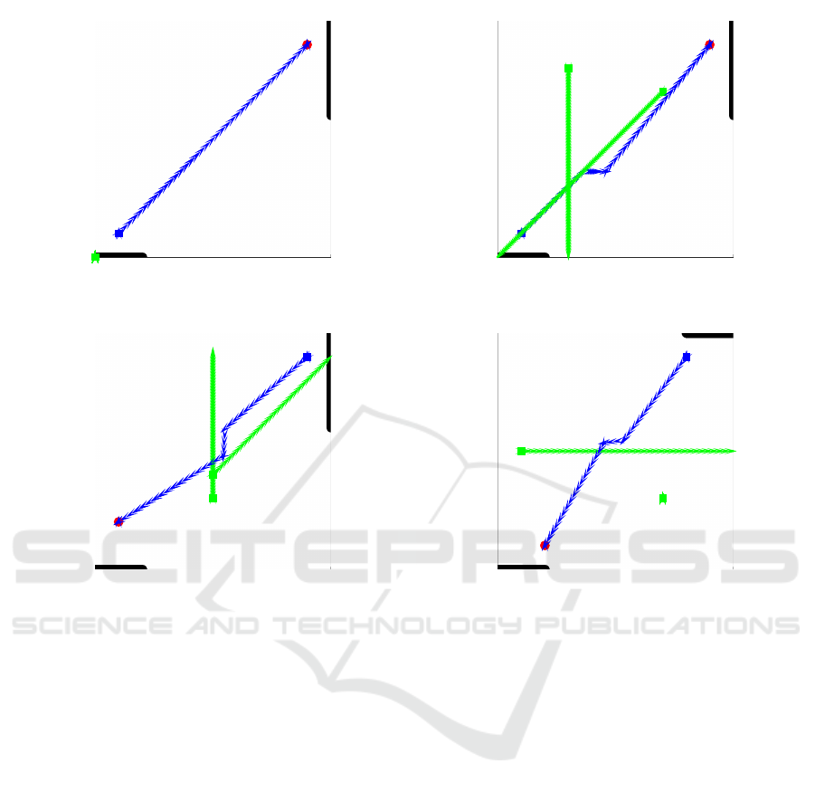
Training requires a dataset consisting of a large
number of heterogeneous scenarios. Figure 9 shows
four complete scenarios, in which there are some sin-
gle docks (in black), the autonomous boat (in blue)
and the other dummy boats (in green). The route
followed by the autonomous boat to reach the goal
(in red) and avoid the other boats on a collision
course is drawn in blue, while the routes followed
by the dummy boats are drawn in green. The Au-
topilot and the Obstacle Avoidance Controller was
used to produce these simulations. Note that the au-
tonomous boat performs different maneuvers to avoid
the dummy boats on a collision course based on their
course direction. This is achieved by applying the
general navigation rules, which are translated into
crisp rules to create the benchmark Obstacle Avoid-
ance Controller. For example, in Figure 9 (b) the au-
tonomous boat turns right to avoid a collision course
boat coming from ahead. Finally, it is worth observ-
ing how maneuvers are straight. The use of fuzzy
rules aims to make the maneuver smoother. Further
considerations are postponed to future publications.
5 CONCLUSIONS
We illustrated our design principles for an au-
tonomous Electric Boat control architecture in order
to define an ADAS-like standard for the marine in-
dustries. The boat is equipped with smart sensors and
an original propulsion system. A Neural Network-
based motion controller drives the propulsion sys-
tem and allows to correct environmental perturbations
2
See the documentation at
https://github.com/cybergalactic/MSS
FCTA 2021 - 13th International Conference on Fuzzy Computation Theory and Applications
192
0 2000 4000 6000 8000 10000
y [m]
0
1000
2000
3000
4000
5000
6000
7000
8000
9000
10000
x [m]
Complete Scenario - Sim.No.1
BOAT
TARGET
OBSTACLE 1OBSTACLE 2
(a)
0 2000 4000 6000 8000 10000
y [m]
0
1000
2000
3000
4000
5000
6000
7000
8000
9000
10000
x [m]
Complete Scenario - Sim.No.2
BOAT
TARGET
OBSTACLE 1
OBSTACLE 2
(b)
0 2000 4000 6000 8000 10000
y [m]
0
1000
2000
3000
4000
5000
6000
7000
8000
9000
10000
x [m]
Complete Scenario - Sim.No.3
BOAT
TARGET
OBSTACLE 1
OBSTACLE 2
(c)
0 2000 4000 6000 8000 10000
y [m]
0
1000
2000
3000
4000
5000
6000
7000
8000
9000
10000
x [m]
Complete Scenario - Sim.No.4
BOAT
TARGET
OBSTACLE 1
OBSTACLE 2
(d)
Figure 9: Complete scenario simulation examples with a benchmark Obstacle Avoidance Controller.
(such as surface water currents), eventually, until vir-
tual anchoring is achieved. A Finite State Machine
switches between several operations according to the
situation recognized by a Supervisor. An Obstacle
Avoidance Controller, a (harbor) Entering Controller
and a (harbor) Exiting Controller have been designed
as Mamdani Fuzzy Controllers, while an Autopilot
has been designed with classical methodologies. The
presented Fuzzy Q-Learning method is intended for
training/adjusting the consequent part of fuzzy rules.
We also propose an all-encompassing reward func-
tion inspired by fish school behavior, which can act
on both the driving of a single boat and the driving
of a small fleet. Development is currently focused
on a single-agent system, but in the future the project
will expand to a multi-agent system in order to redis-
tribute resources, the computational load and further
improve the efficiency and sustainability of the local
transport system. The ensemble architecture could be
improved by integrating other Fuzzy Controller-based
pipelines without having to redesign the entire archi-
tecture. Furthermore, the overall performance of the
automata could be improved by using inductive logic
inferences also in the supervision level. It will be-
come the subject of study at the end of the present
project phase.
A simulator based on several MATLAB
R
Tool-
boxes has been illustrated. Future works will be
grounded on heavy simulation sessions together with
tests conducted in a real-world scenario using the
Electric Boat Valentino III. For this reason, we aim to
transfer the system architecture on a dedicated Nvidia
HW. We will compare the performances achieved by
the virtual boat and the real one to validate both our
simulator and our real-world architecture.
ACKNOWLEDGEMENTS
The Department of Information Engineering, Elec-
tronics and Telecommunications (DIET) at University
of Rome La Sapienza and the Po.Mo.S Laboratories
would like to thank the EU for financial support to en-
vironmental and climate action projects like LIFE for
A Modular Autonomous Driving System for Electric Boats based on Fuzzy Controllers and Q-Learning
193

Silver Coast (LIFE16 ENV/IT/000337). Such a help
is crucial to achieve natural and historical preserva-
tion of Italy, especially of touristic areas.
REFERENCES
Aguercif, T., Tighzert, L., Mendil, B., and Fonlupt, C.
(2017). Rate learning-based fish school search al-
gorithm for global optimization. In 2017 6th Inter-
national Conference on Systems and Control (ICSC),
pages 520–525.
Akiyama, T., Kobayashi, Y., Kishigami, J., and Muto, K.
(2018). Cnn-based boat detection model for alert
system using surveillance video camera. In 2018
IEEE 7th Global Conference on Consumer Electron-
ics (GCCE), pages 669–670.
Bianchi, F. M., De Santis, E., Rizzi, A., and Sadeghian,
A. (2015). Short-term electric load forecasting using
echo state networks and pca decomposition. Ieee Ac-
cess, 3:1931–1943.
Bojarski, M., Testa, D., Dworakowski, D., Firner, B., Flepp,
B., Goyal, P., Jackel, L., Monfort, M., Muller, U.,
Zhang, J., Zhang, X., Zhao, J., and Zieba, K. (2016).
End to end learning for self-driving cars. ArXiv,
abs/1604.07316.
Boujelben, M., Ayedi, D., Rekik, C., and Derbel, N. (2017).
Fuzzy logic controller for mobile robot navigation to
avoid dynamic and static obstacles. In 2017 14th In-
ternational Multi-Conference on Systems, Signals De-
vices (SSD), pages 293–298.
Boujelben, M., Rekik, C., and Derbel, N. (2013). Hierar-
chical fuzzy controller to avoid mobile obstacle for a
mobile robot. In 10th International Multi-Conferences
on Systems, Signals Devices 2013 (SSD13), pages 1–
8.
Brehmer, P., Sarr
´
e, A., Gonzalez, L., Cotel, P., Hermand, J.-
P., and Franc¸ois, G. (2013). Aggregative and school-
ing behaviour of small pelagic fish schools through
echo type characteristics. In 2013 IEEE/OES Acous-
tics in Underwater Geosciences Symposium, pages 1–
6.
Cai, L. and Sun, Q. (2017). A regular expression group-
ing algorithm based on artificial fish school algorithm.
In 2017 7th IEEE International Conference on Elec-
tronics Information and Emergency Communication
(ICEIEC), pages 556–559.
Cherroun, L. and Boumehraz, M. (2012). Intelligent sys-
tems based on reinforcement learning and fuzzy logic
approaches, ”application to mobile robotic”. In 2012
International Conference on Information Technology
and e-Services, pages 1–6.
Chu, J., Gu, W., and Chen, X. (2008). Study on adaptive
control of the propelling and turning manoeuvre of an
autonomous water vehicle for ocean observation. In
OCEANS 2008, pages 1–4.
De Santis, E., Livi, L., Sadeghian, A., and Rizzi, A. (2015).
Modeling and recognition of smart grid faults by a
combined approach of dissimilarity learning and one-
class classification. Neurocomputing, 170:368–383.
De Santis, E., Paschero, M., Rizzi, A., and Masci-
oli, F. M. F. (2018). Evolutionary optimization of
an affine model for vulnerability characterization in
smart grids. In 2018 International Joint Conference
on Neural Networks (IJCNN), pages 1–8. IEEE.
De Santis, E., Rizzi, A., Sadeghiany, A., and Mascioli, F.
M. F. (2013). Genetic optimization of a fuzzy control
system for energy flow management in micro-grids. In
2013 Joint IFSA World Congress and NAFIPS Annual
Meeting (IFSA/NAFIPS), pages 418–423. IEEE.
De Santis, E., Sadeghian, A., and Rizzi, A. (2017). A
smoothing technique for the multifractal analysis of a
medium voltage feeders electric current. International
Journal of Bifurcation and Chaos, 27(14):1750211.
Duan, Y. and Xin-Hexu (2005). Fuzzy reinforcement learn-
ing and its application in robot navigation. In 2005
International Conference on Machine Learning and
Cybernetics, volume 2, pages 899–904 Vol. 2.
Elkins, L., Sellers, D., and Monach, W. R. (2010). The
autonomous maritime navigation (amn) project: Field
tests, autonomous and cooperative behaviors, data fu-
sion, sensors, and vehicles. Journal of Field Robotics,
27(6):790–818.
Ferrandino., E., Capillo., A., Mascioli., F., and Rizzi., A.
(2020). Nanogrids: A smart way to integrate public
transportation electric vehicles into smart grids. Pro-
ceedings of the 12th International Joint Conference
on Computational Intelligence - CI4EMS,, pages 512–
520.
Fossen, T. I. (2021). Handbook of Marine Craft Hydrody-
namics and Motion Control. Wiley.
Fujiwara, C., Onishi, N., Tateyama, T., Hiratsuka, S.,
Sakakibara, K., and Chen, Y.-W. (2012). Behav-
ior generation of fish school by the potential field
method in virtual aqua museum. In 2012 6th Interna-
tional Conference on New Trends in Information Sci-
ence, Service Science and Data Mining (ISSDM2012),
pages 495–498.
Glorennec, P. Y. (1996). Fuzzy logic-based navigation for
an autonomous robot. IFAC Proceedings Volumes,
29(4):45–49. IFAC Workshop on Intelligent compo-
nents for Autonomous and Semi-Autonomous Vehi-
cles, Toulouse, France, 25-26 October.
Grigorescu, S., Trasnea, B., Cocias, T., and Macesanu,
G. (2020). A survey of deep learning techniques
for autonomous driving. Journal of Field Robotics,
37(3):362–386.
He, K., Sun, H., and Cheng, W. (2008). Application of
fuzzy neural network based on t-s model for mobile
robot to avoid obstacles. 2008 7th World Congress
on Intelligent Control and Automation, pages 8282–
8285.
Hong, J., Tang, K., and Chen, C. (2017). Obstacle avoid-
ance of hexapod robots using fuzzy q-learning. In
2017 IEEE Symposium Series on Computational In-
telligence (SSCI), pages 1–6.
Kobayashi, E.-i., Yoneda, S., and Morita, A. (2014). Ad-
vanced route optimization in ship navigation. In
Proceedings of the 4th International Conference on
Simulation and Modeling Methodologies, Technolo-
gies and Applications, page 572–577, Setubal, PRT.
FCTA 2021 - 13th International Conference on Fuzzy Computation Theory and Applications
194

SCITEPRESS - Science and Technology Publications,
Lda.
Labuguen, R. T., Volante, E. J. P., Causo, A., Bayot, R.,
Peren, G., Macaraig, R. M., Libatique, N. J. C., and
Tangonan, G. L. (2012). Automated fish fry count-
ing and schooling behavior analysis using computer
vision. In 2012 IEEE 8th International Colloquium
on Signal Processing and its Applications, pages 255–
260.
Lai, L. and Qu, S. (2011). Research on application of fish
swarm behaviour in intelligent transportation system.
In 7th Advanced Forum on Transportation of China
(AFTC 2011), pages 195–200.
Leonori, S., Paschero, M., Rizzi, A., and Mascioli, F.
(2017). An optimized microgrid energy management
system based on fis-mo-ga paradigm. Institute of
Electrical and Electronics Engineers Inc.
Li, J., Cheng, H., Guo, H., and Qiu, S. (2018a). Survey on
artificial intelligence for vehicles. Automotive Innova-
tion, 1:2–14.
Li, L., Ota, K., and Dong, M. (2018b). Humanlike driving:
Empirical decision-making system for autonomous
vehicles. IEEE Transactions on Vehicular Technol-
ogy, 67(8):6814–6823.
Li, X., Zhou, Z., Li, X., and Wan, Y. (2012). Vehicle
segmentation and speed detection based on binocu-
lar stereo vision. In 2012 Eighth International Con-
ference on Computational Intelligence and Security,
pages 369–373.
Liang, S., Zhi-ming, Q., and Heng, L. (2018). A survey on
route planning methods of auv considering influence
of ocean current. 2018 IEEE 4th International Con-
ference on Control Science and Systems Engineering
(ICCSSE), pages 288–295.
Liu, Q., gang Lu, Y., and xi Xie, C. (2006). Fuzzy obstacle-
avoiding controller of autonomous mobile robot opti-
mized by genetic algorithm under multi-obstacles en-
vironment. In 2006 6th World Congress on Intelligent
Control and Automation, volume 1, pages 3255–3259.
Ma, K., Zhou, H., Li, J., and Liu, H. (2019). Design of
binocular stereo vision system with parallel optical
axesand image 3d reconstruction. In 2019 China-
Qatar International Workshop on Artificial Intelli-
gence and Applications to Intelligent Manufacturing
(AIAIM), pages 59–62.
Pambudi, A. D., Agustinah, T., and Effendi, R. (2019). Re-
inforcement point and fuzzy input design of fuzzy q-
learning for mobile robot navigation system. In 2019
International Conference of Artificial Intelligence and
Information Technology (ICAIIT), pages 186–191.
Plumet, F., P
ˆ
etr
`
es, C., Romero-Ramirez, M., Gas, B., and
Ieng, S. (2015). Toward an autonomous sailing boat.
IEEE Journal of Oceanic Engineering, 40:397–407.
Prabhakar, G., Kailath, B., Natarajan, S., and Kumar, R.
(2017). Obstacle detection and classification using
deep learning for tracking in high-speed autonomous
driving. In 2017 IEEE Region 10 Symposium (TEN-
SYMP), pages 1–6.
Sakagami, N. and Terao, Y. (2012). Development of a mea-
surement and autonomous control system for wave-
powered boats. In 2012 Oceans - Yeosu, pages 1–6.
Sharma, R. (2014). Fuzzy q learning based uav autopilot.
In 2014 Innovative Applications of Computational In-
telligence on Power, Energy and Controls with their
impact on Humanity (CIPECH), pages 29–33.
Siddique, N. and Adeli, H. (2013). Computational Intel-
ligence: Synergies of Fuzzy Logic, Neural Networks
and Evolutionary Computing. Wiley.
Son, N.-s. and Kim, S.-Y. (2018). On the sea trial test for the
validation of an autonomous collision avoidance sys-
tem of unmanned surface vehicle, aragon. In OCEANS
2018 MTS/IEEE Charleston, pages 1–5.
Swain, D. T., Couzin, I. D., and Ehrich Leonard, N. (2012).
Real-time feedback-controlled robotic fish for behav-
ioral experiments with fish schools. Proceedings of
the IEEE, 100(1):150–163.
Tsai, C.-M., Lai, Y.-H., Perng, J.-W., Tsui, I.-F., and Chung,
Y.-J. (2019). Design and application of an autonomous
surface vehicle with an ai-based sensing capability. In
2019 IEEE Underwater Technology (UT), pages 1–4.
U.S.C.G. (2017). Navigation Rules: International-Inland.
U.S. Coast Guard Marine Transportation Systems Di-
rectorate and Navigation Center of Excellence.
Wang, J., Xiao, Y., Li, T., and Chen, C. L. P. (2020). A
survey of technologies for unmanned merchant ships.
IEEE Access, 8:224461–224486.
Weng, Y., Wang, N., Qin, H., Karimi, H. R., and Qi, W.
(2018). Data-driven adaptive tracking control of un-
known autonomous marine vehicles. IEEE Access,
6:55723–55730.
Xia, W., Li, H., and Li, B. (2016). A control strategy of au-
tonomous vehicles based on deep reinforcement learn-
ing. In 2016 9th International Symposium on Compu-
tational Intelligence and Design (ISCID), volume 2,
pages 198–201.
Zhuang, X., chun Meng, Q., Yin, B., and Wang, H.-
P. (2002). Robot path planning by artificial poten-
tial field optimization based on reinforcement learn-
ing with fuzzy state. Proceedings of the 4th World
Congress on Intelligent Control and Automation (Cat.
No.02EX527), 2:1166–1170 vol.2.
A Modular Autonomous Driving System for Electric Boats based on Fuzzy Controllers and Q-Learning
195
