
Driving Video Prediction based on Motion Estimation of 3D Objects
using a Stereo Camera System
Takuya Umemura, Fumihiko Sakaue and Jun Sato
Nagoya Institute of Technology, Gokiso, Show, Nagoya 466-8555, Japan
Keywords:
Future Image Prediction, Driving Assist, Deep Image Prior.
Abstract:
In this paper, we propose a method to synthesize future images in a driving scene using a stereo camera system
fitted on vehicles. In this method, three-dimensional (3D) objects in a driving scenario, such as vehicles,
buildings, and humans, are reconstructed by a stereo camera system. The reconstructed objects are separated
by semantic image segmentation based on 2D image information. Furthermore, motion prediction using a
Kalman filter is applied to each object. 3D objects in future scenes are rendered using this motion prediction.
However, some regions, which are occluded in the input images, cannot be predicted. Therefore, an image
inpainting technique is used for the occluded regions in the input image. Experimental results show that our
proposed method can synthesize natural predicted images.
1 INTRODUCTION
In recent years, various information processing tech-
nologies, such as automated driving and driving as-
sistance, have been installed in vehicles, and these
techniques have been researched and developed ex-
tensively. Typically, in such technologies, various
data are obtained from different kinds of sensors, such
as cameras and 3D sensors, and the system assists
drivers based on this data.
These systems inherently have a delay because it
takes some time to acquire and process the data. Thus,
we cannot obtain “real” real-time information through
the sensors. Moreover, recent systems obtain data
from not only installed sensors but also surrounding
sensors, e.g., sensors on the other vehicles and street
cameras, through the network. Similarly, remote driv-
ing systems developing recently receive information
from the vehicle through the network to drive the ve-
hicle from far away. In these cases, the delay of the
data becomes larger since data transmission through
the network requires lots of time. Therefore, the de-
lay cannot be ignored for achieving safety operations.
If the system has an information delay, it is difficult
to replicate the acquired information in real-time op-
erations. For example, in cases where the vehicle
should prevent collision with a pedestrian who ap-
pears suddenly, a system with a time delay can lead
to grave consequences. Therefore, the delay in the
feedback time from acquisition to processing of in-
formation should be considered as a critical problem
to be solved.
To solve this problem, it is vital to minimize the
response time of the system. However, the acquisi-
tion, processing and transmission of information takes
a specific duration in principle, which cannot be 0 s.
Therefore, we attempt to solve this problem by pre-
dicting the transition of the whole scene instead of
shortening the delay time. If such a scene predic-
tion system is developed, the delay problem can be
avoided. That is, even when the information from the
sensor has a delay, the predicted data can correspond
to the real-time data, and the predicted data can be uti-
lized in real-time driving. In this research, we focus
on images taken by the camera fitted on the vehicles.
In this paper, we propose an image prediction tech-
nique, using images taken by an in-vehicle camera of
the driving scene.
Recently, several video image prediction methods
have been proposed (Vondrick et al., 2016; Vondrick
and Torralba, 2017; Finn et al., 2016). In these meth-
ods, deep neural networks are used for predicted im-
age synthesis. Notably, generative adversarial net-
work (GAN) is one of the most effective architec-
tures to synthesize images. In the image generating
network, a model that describes scene transitions is
implicitly trained in the network, which synthesizes
the future image from the current input image, based
on this implicit model. Although the network pre-
dicts the future image when the model fits the input
Umemura, T., Sakaue, F. and Sato, J.
Driving Video Prediction based on Motion Estimation of 3D Objects using a Stereo Camera System.
DOI: 10.5220/0009349108590866
In Proceedings of the 15th International Joint Conference on Computer Vision, Imaging and Computer Graphics Theory and Applications (VISIGRAPP 2020) - Volume 5: VISAPP, pages
859-866
ISBN: 978-989-758-402-2; ISSN: 2184-4321
Copyright
c
2022 by SCITEPRESS – Science and Technology Publications, Lda. All rights reserved
859

scene, many images are required to train the network
correctly. Furthermore, these methods mainly focus
on the partial transition of the scene. Therefore, the
process may not be suitable in predicting a driving
scene because the entire image significantly changes
depending on the camera motion in the driving scene.
Furthermore, such case-based methods are not suit-
able for predicting unusual events because it is not
easy to collect training data of unusual scenes.
In contrast, our proposed method has an explicit
scene transition model for image prediction. The
model is based on a physical model as opposed to a
training case, which we can control and explain; thus,
our proposed method does not require a training im-
age set to optimize the image prediction. Therefore,
our proposed method can predict future images even
in unusual events, e.g., traffic accidents.
2 IMAGE PREDICTION IN
DRIVING SCENE
2.1 System Construction
For image prediction in a driving scene, we consider
the type of scene taken by the cameras fitted on the
vehicles. When the camera runs on the road, the im-
ages contain pedestrians, vehicles driving, and build-
ings around the road. The objects typically move in-
dependently, and should be separated to estimate and
predict their movement. Because the motion of the
object is not 2D but 3D, 3D measurement of the ob-
jects is required to predict their movement.
Therefore, we first measure the 3D road scenes us-
ing a stereo camera system and predict the scene us-
ing the 3D information obtained from them. We sepa-
rate the measured map into multiple objects, and each
object’s motion is estimated. From the estimated mo-
tions, the object’s future position is predicted. Finally,
we render a future image from the expected state and
measure its 3D shape.
In recent studies, a method using a laser sen-
sor such as light detection and ranging (LiDAR) has
been considered for acquiring accurate 3D informa-
tion. However, we choose a stereo camera system be-
cause the cameras can measure dense depth maps in
real-time. Additionally, the stereo system can receive
3D shapes and a 2D image, which have much infor-
mation. Therefore, the stereo camera system is suit-
able for predicting the driving scene in our research.
Note that the distance measurement results ob-
tained by the stereo camera are less accurate than the
result from LiDAR. However, in the synthesis of a
future image, it is not a significant issue. As the dis-
tant 3D points that are less accurate are projected to a
small region in the image, the effect of the accuracy
degradation is suppressed in the predicted image.
2.2 3D Reconstruction by the Stereo
Camera
We first explain 3D scene reconstruction using the
stereo camera system. The 3D reconstruction of the
image is based on epipolar geometry. Let us consider
the case when the stereo cameras are calibrated, and
camera projection matrices P
1
and P
2
are computed
in advance. When correspondences m
1
and m
2
are
detected from each camera image, the 3D point X,
which corresponds to the image points is measured as
follows:
X = arg min
X
2
∑
i=1
km
i
− P
i
(X)k
2
(1)
where P
i
(X) is the projection of the point X to the i-th
camera. As shown in the equation, the 3D points are
reconstructed by minimizing the reprojection error.
As mentioned above, 3D points are reconstructed
when correspondences are detected from stereo im-
ages. Therefore, accurate 3D shape reconstruction
from the stereo image depends on the accurate detec-
tion of corresponding feature points. The correspon-
dence detection is achieved by epipolar geometry us-
ing a 1D search as the correspondences are on epipo-
lar lines. Therefore, image rectification is applied to
stereo images, which makes the epipolar lines parallel
to the horizontal axis. In this case, finding correspon-
dences is equivalent to the estimation of the disparity
in each pixel.
In recent studies, the estimation of the disparity is
optimized in the entire image, i.e., a 2D regularizing
constraint is applied to achieve stable estimation. Es-
pecially, semi-global matching (SGM)(Hirschmuller,
2005) is widely used because the method provides
a better disparity map at a low computational cost.
The technique uses several 1D constraints for reduc-
ing computational cost rather than a 2D constraint.
Thus, the required computational cost is much smaller
than in the case when 2D optimization is used. In
our method, the computational cost should be low
because our method needs to operate in real-time.
Therefore, we use the SGM to compute the dispar-
ity map from the stereo images efficiently. Figure 1
shows the computed disparity by SGM. Using the
SGM, a disparity map in the driving scene can be esti-
mated, and a dense 3D map is reconstructed from the
map.
VISAPP 2020 - 15th International Conference on Computer Vision Theory and Applications
860
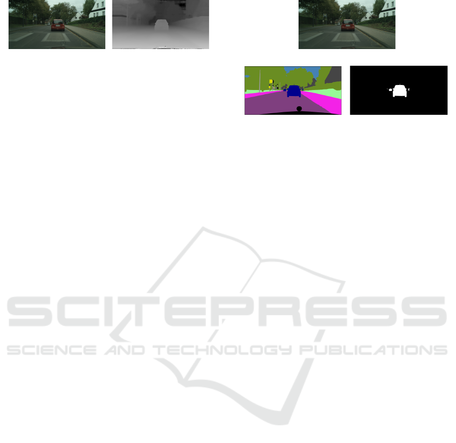
(a) input image
(b) disparity map
Figure 1: Disparity map by SGM.
2.3 Object Segmentation
Next, we consider the object segmentation of the mea-
sured 3D map. As mentioned, the 3D point cloud
from the stereo camera includes different kinds of 3D
objects, which move independently. Therefore, it is
necessary to segment 3D points to multiple objects to
predict the scene transition accurately. The segmen-
tation of the 3D points is often based on the motion
of the points. However, when the object motion is
inaccurate, this segmentation is challenging. For ex-
ample, when two or three frames are taken in a short
duration are used to estimate the object’s motion, the
estimated motion has many estimation errors, and it
cannot provide enough information to separate the ob-
jects. Therefore, a method based on motion is not
suitable for this research. Consequently, we classify
the object based on 3D image data instead of motion
because camera images can be used in our method.
To achieve image segmentation in the driv-
ing scene, we use semantic segmentation of im-
ages(Sharma et al., 2018). Semantic segmentation
adds image labels pixel by pixel, and the pixels are
classified into people, roads, and vehicles. In recent
years, convolutional neural networks (CNN) are often
used for semantic segmentation(Sharma et al., 2018).
The CNN can label the pixels at high speed and accu-
racy. As objects with different labels are considered
to perform different motions, it is possible to separate
the motions using the semantic segmentation results.
In this research, conditional GAN(Isola et al.,
2016) is utilized to achieve semantic segmentation in
the driving scene. Using the conditional GAN, natural
input images are converted to image labels, and thus
image segmentation is accomplished. In this segmen-
tation, a limited number of labels are used as objects,
which appear in the road scene are limited. Further-
more, a detailed label is not required in our method
because we aim to separate the objects by their mo-
tion. Therefore, the labels are integrated into two la-
bels, dynamic and static objects.
The dynamic objects can move independently, and
they include humans and vehicles. In the dynamic ob-
jects, there are multiple objects, which have different
motions. Therefore, detailed segmentation results are
preserved because the motion of these objects should
be estimated independently. The static objects include
(a) Input image
(b) Semantic segmentation (c) Segmentation of results
into dynamic and static objects
Figure 2: Example of object segmentation by semantic seg-
mentation: (a) shows the input image, (b) shows the seman-
tic segmentation result, and (c) shows the segmentation re-
sult of static and dynamic objects. In image (c), dynamic
objects are shown by white pixels and static objects by black
pixels.
buildings and roads. They cannot move by them-
selves; therefore, the relative motion of the objects
is caused by camera motion. Thus, their motion is es-
timated concurrently as a camera motion. Since the
3D points in the scene correspond to the pixels in the
input image, it is possible to label the recovered 3D
point group and obtain a separate point group for each
object because of the segmentation. An example of
image segmentation using CNN is shown in Fig. 2.
This example shows that vehicles, pedestrians, and
road surfaces are given different labels, and the ob-
jects in the scene can be properly separated in Fig. 2
(b). Furthermore, the labels are integrated into static
and dynamic objects, as shown in Fig. 2(c).
3 MOTION ESTIMATION AND
PREDICTION OF 3D OBJECT
3.1 Object Corresponding
Next, we consider a method to estimate the motion
data of each separated 3D object. Using image seg-
mentation, it is possible to obtain a 3D position of the
separated objects at each time. However, it is neces-
sary to find the corresponding objects for estimating
their motion. In this research, SIFT(Lowe, 2004) is
used for object matching. The SIFT is a local image
feature, and it is often used for detecting matching
points. The SIFT feature is robust against illumina-
tion change, image rotation, and scaling. In the driv-
ing scene captured by vehicle cameras, illumination
of the scene changes given the sunshine conditions.
Moreover, the scale and rotation of the object image
change with the object’s movement. Therefore, we
Driving Video Prediction based on Motion Estimation of 3D Objects using a Stereo Camera System
861

expect that these differences can be suppressed using
SIFT.
For motion estimation, SIFT points are detected
from the images in each frame. The corresponding
points are found in the neighboring frame based on
the SIFT feature. The corresponding object can be
identified using SIFT matching because identical ob-
jects have corresponding feature points.
Note that, we obtain not only 2D point correspon-
dences but also 3D point correspondences since the
image has 3D information at each point by the stereo
method. These 3D correspondences are utilized for
motion estimation described in the next section.
3.2 Motion Estimation based on
Kalman Filter
Here, we discuss motion estimation. In this estima-
tion, we assume that objects in the scene are rigid.
Under this assumption, the motions of the objects are
only rotation and translation. Therefore, we only es-
timate the rotation and the translation of objects from
input images.
For this estimation, corresponding SIFT points in
the object are used. Let X
j,i
t−1
denote the i-th 3D point
with label j at time t − 1. The point X
j,i
t−1
corresponds
to the point X
j,i
t
at time t. In this case, a rotation ma-
trix R
j0
t
and translation vector T
j0
t
between t and t − 1
can be estimated as follows:
(R
t
j0
, T
t
j0
) = arg min
R,T
n
∑
i
||X
j,i
t
− (RX
j,i
t−1
+ T)|| (2)
Using this estimation, the motion of each object can
be predicted.
However, because the measured 3D point is af-
fected by noise, such as the reconstruction error in
the stereo method, a reliable estimation cannot be ex-
pected using only two frames. Therefore, a Kalman
filter(Kalman, 1960) is used to achieve reliable mo-
tion estimation and prediction.
The Kalman filter is an iterative estimator that
takes an observed value of the current time as an in-
put. The filter sequentially updates the state of the
model while providing an estimated value of the cur-
rent time and a predicted value of the time ahead. In
this research, when the transition time interval is 1
min, it is assumed that the transition of each motion
parameter can be approximated by a linear form, and
this is expressed using a linear Kalman filter.
Let T
j
t
and a
j
t
denote the translation and acceler-
ation of the j-th object at time t. In this case, we as-
sume that the object moves with uniform acceleration
approximately, and the prediction model of motion
from T
j
t−1
to the predicted translation
ˆ
T
j
t
is defined
as follows:
ˆ
T
j
t
a
j
t
=
I I
0 I
"
T
j
t−1
a
j
t−1
#
(3)
where I denotes a 3 × 3 identity matrix and 0 denotes
a 3×3 all zero matrix. In addition, it assumes that the
transition of the prediction error covariance matrix P
j
t
is defined as follows:
ˆ
P
j
t
=
I I
0 I
P
j
t−1
I I
0 I
T
+ N (0, Q
t
) (4)
where N (0, Q
t
) is a zero means normal distribution
with a covariance matrix Q
t
. According to the esti-
mated translation vector T
j
t
0
, all parameters for esti-
mation are updated as follows:
e
t
= T
j
t
0
−
I 0
ˆ
T
j
t
a
j
t
(5)
S
t
= Q
t
+
I 0
ˆ
P
j
t
I 0
T
(6)
K
t
=
ˆ
P
j
t
I 0
T
S
−1
t
(7)
T
j
t
=
ˆ
T
j
t
+ K
t
e
t
(8)
P
j
t
= (I − K
t
I 0
)
ˆ
P
j
t
(9)
The updated T
j
t
is a motion of the j -th object consid-
ering past frames and
ˆ
T
j
t+1
is the predicted translation
in the next frame.
Similar to the estimation of the translation, a ro-
tation matrix R
j
t
and
ˆ
R
j
t+1
is estimated. In this esti-
mation, the matrix R
j
t
is converted to a rotation vector
r
j
t
by Rodrigues’ formula. Then, the Kalman filter is
applied to the rotation vector, and the rotation R
j
t
is
estimated.
A Kalman filter is applied to the translation and
rotation estimation according to the model; conse-
quently, object motion can be estimated while sup-
pressing the effect of noise. Furthermore, it is possi-
ble to predict the motion of the object by finding the
parameters of the next frame based on the Kalman fil-
ter. From these predicted parameters, the 3D point
X
j
t+1
is predicted as follows:
X
j
t+1
=
ˆ
R
j
t+1
X
j
t
+
ˆ
T
j
t+1
(10)
Using these predicted shapes in the next frame, a fu-
ture image can be rendered.
3.3 Image Inpainting by Deep Image
Prior
The future image, which is synthesized using the
method mentioned above is constructed based on the
VISAPP 2020 - 15th International Conference on Computer Vision Theory and Applications
862
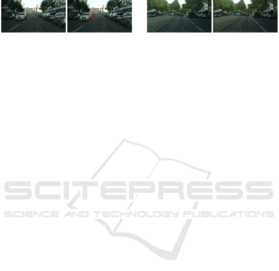
(a) input image (b) predicted image
Figure 3: Example of a missing area caused by an occlusion
in predicted images.
observation image of the current time. Therefore, the
appropriate image cannot be synthesized when sev-
eral regions in the future images cannot be observed
at the current time due to occlusions. For example,
Fig. 3 shows a scene where the vehicle fitted camera
is moving forward, and the vehicle in the left part of
the image is also moving forward. In this case, the re-
gion occluded by the front vehicle in the current frame
cannot be rendered and is not in the predicted image,
as shown in the red area. Therefore, to synthesize a
natural predicted image, it is necessary to interpolate
such missing regions correctly.
A method to interpolate such a missing image
is called inpainting, and various methods have been
proposed(Yu et al., 2018). In our system, the miss-
ing region is interpolated based on a deep image
prior(Ulyanov et al., 2018). The deep image prior is
one of the image synthesis methods of CNN. The im-
age synthesis in the deep image prior is based on the
network architecture combined with some image data
rather than training images. Therefore, the method
does not need training on CNN. Thus, an image can
be interpolated without training the network using the
deep image prior.
Let us consider the case where the network archi-
tecture f synthesizes an image f (z, W) similar to an
image x based on input noise z and parameters W
of the network. Furthermore, the image x includes
a missing region and an image mask m replacing the
region to 0 as xm. In this case, the deep image prior
optimizes the parameters W by minimizing E for in-
terpolating the missing region as follows:
E = ||( f (W, z) − x) m||
2
(11)
From the estimated W, image f (W, z) is synthesized
without any missing regions. Furthermore, by replac-
ing the missing part of the generated image, the inter-
polated image can be synthesized. A natural predicted
image can be synthesized without any missing regions
using this method.
In the general case, the image is estimated from
the randomly generated noise image z. However, in
this research, we use the observation image x
t
at the
current time instead of the noise. In this case, the im-
age is synthesized based on the evaluation equation as
follows:
Figure 4: CityScapes Dataset.
E = ||( f (W, x
t
) − x) m||
2
(12)
As the image of the current time and future time have
a strong correlation with each other, it can be expected
that the image can be synthesized more effectively
and efficiently from the current image. Additionally,
our research targets sequential video frames, and it
is considered that the images at continuous times are
similar. Therefore, the image generation network W
is also the same in each frame. Thus, the estimated pa-
rameters in the previous frame are used as the initial
parameters of the network. As a result, more efficient
parameter estimation can be achieved; hence this ini-
tialization can reduce the image estimation time.
4 EXPERIMENTAL RESULTS
4.1 Environment
In this section, we show several experimental results
of our proposed method. In these experiments, we
used CityScapes Dataset(Cordts et al., 2016). The
dataset includes many videos taken by the stereo cam-
eras in several cities. The framerate of the videos is
17 fps. An example of the image included in the data
set is shown in Fig.4.
Moreover, the dataset includes image labels for se-
mantic segmentation. In this dataset, 2975 sequences
were used for training the CNN for semantic segmen-
tation, and the others were used as test data.
4.2 Image Prediction Results
The predicted images of the proposed method are
shown in Fig. 5. In the figures, (a) represents an
image at the current time, (b) represents the dispar-
ities obtained from SGM, (c) represents the results
of semantic segmentation to dynamic and static ob-
jects, and (d) represents the predicted images in the
next frame using our method. The ground truth of
the predicted images is shown in (e). Furthermore,
(f) shows an image where the predicted image and
ground-truth image are multiplexed. In these mul-
tiplexed images, the red component of each pixel is
from the ground-truth. The green and blue compo-
nents are from the predicted images. The locations,
Driving Video Prediction based on Motion Estimation of 3D Objects using a Stereo Camera System
863
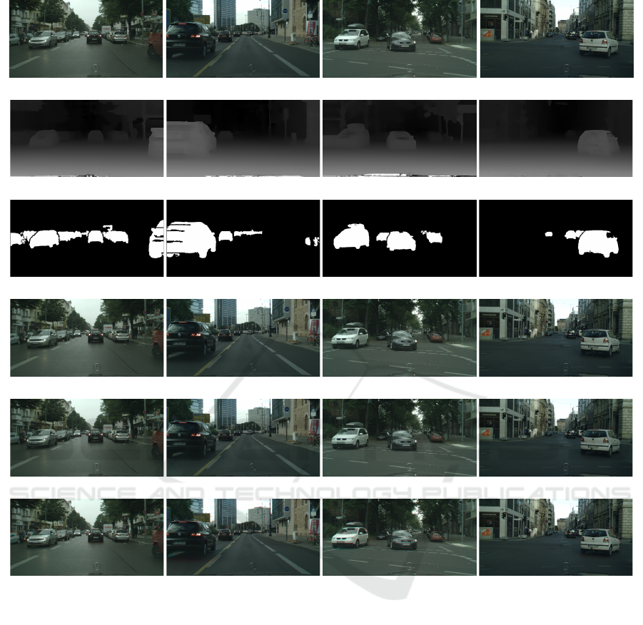
(a) input images
(b) measured disparities
(c) semantic segmentation
(d) predicted images
(e) ground-truth
(f) multiplexed images of the predicted images and ground-truth
Figure 5: Experimental results on a straight road: (a) input image, (b) measured disparities, (c) semantic segmentation results,
(d) predicted images, (e) ground-truth and (f) comparison between ground-truth and predicted images are shown.
where the color shifts occur, show the difference be-
tween the predicted images and ground-truth.
In these results, the predicted results are similar to
the ground-truth. Moreover, a significant color shift
does not occur in the multiplexed image, which indi-
cates that our proposed method can predict future im-
ages accurately. Notably, the third image include mul-
tiple objects that move independently. For example,
when our vehicle turns to the right, the right vehicle
in the video turns to the right and left vehicle moves
forward in the figure. Despite these complex move-
ments in the scene, the synthesized image is similar
to the ground-truth. These results indicate that the
method can predict the future condition of each ob-
ject independently, and it is practical to synthesize the
correctly predicted images.
Figure 6 shows longer span prediction results. In
this figure, the prediction results based on the current
input image are shown in the right column in Fig.5,
from one frame (59 ms) ahead to four frames (256
ms) ahead, are shown in each column. Remarkably,
natural images can be predicted when a four frames
ahead image is predicted. Although some differences
are found in (iii) the multiplexed image, (ii) the pre-
dicted images are relatively accurate. The results in-
dicate that our proposed method is reliable, and it can
predict future images.
Figure 7 shows another longer span prediction re-
sults. In this figure, the same frame images were es-
timated from the different input images. Each col-
VISAPP 2020 - 15th International Conference on Computer Vision Theory and Applications
864
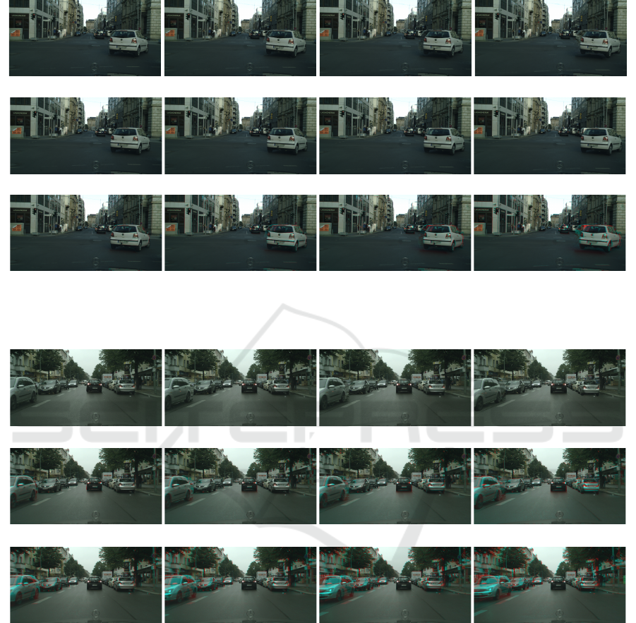
(a) 1 frame (b) 2 frame (c) 3 frame (d) 4 frame
(i) predicted images
(ii) ground-truth
(iii) multiplexed images
Figure 6: Long span prediction results: Top row shows predicted images of our proposed method. Second row shows the
ground truth, and third row shows multiplexed images of the predicted images and ground truth.
(a) 1 frame ago (a) 2 frame ago (a) 3 frame ago (a) 4 frame ago
(i) predicted images
(ii) multiplexed images of predicted results and ground truth
(iii) multiplexed images of input images and ground truth
Figure 7: Comparison between long span prediction and short span prediction: Each column shows predicted results and
multiplex image from1∼4 frames ago images.
umn in the first and second row shows predicted re-
sults and multiplexed images from 1∼4 ago images,
respectively. The third row shows multiplexed images
of input images and ground-truth. In this result, (iii)
row shows input images are much different from the
ground-truth since the change of the whole image is
very large. In contrast, the difference between pre-
dicted images and ground-truth is tiny. The fact indi-
cates that our proposed method can predict the change
of the image even if the whole image changes drasti-
cally.
4.3 Evaluation
We last show the evaluation results of our image pre-
diction. In this evaluation, we chose 20 sequence,
which includes 600 images, from the CityScapes
dataset, and we synthesized predicted images for all
chosen images.
We first evaluated the effectiveness of image in-
painting by deep image prior. In this experiment, pre-
dicted images are estimated from 1 frame ago images
and RMSE between the ground-truth and predicted
Driving Video Prediction based on Motion Estimation of 3D Objects using a Stereo Camera System
865
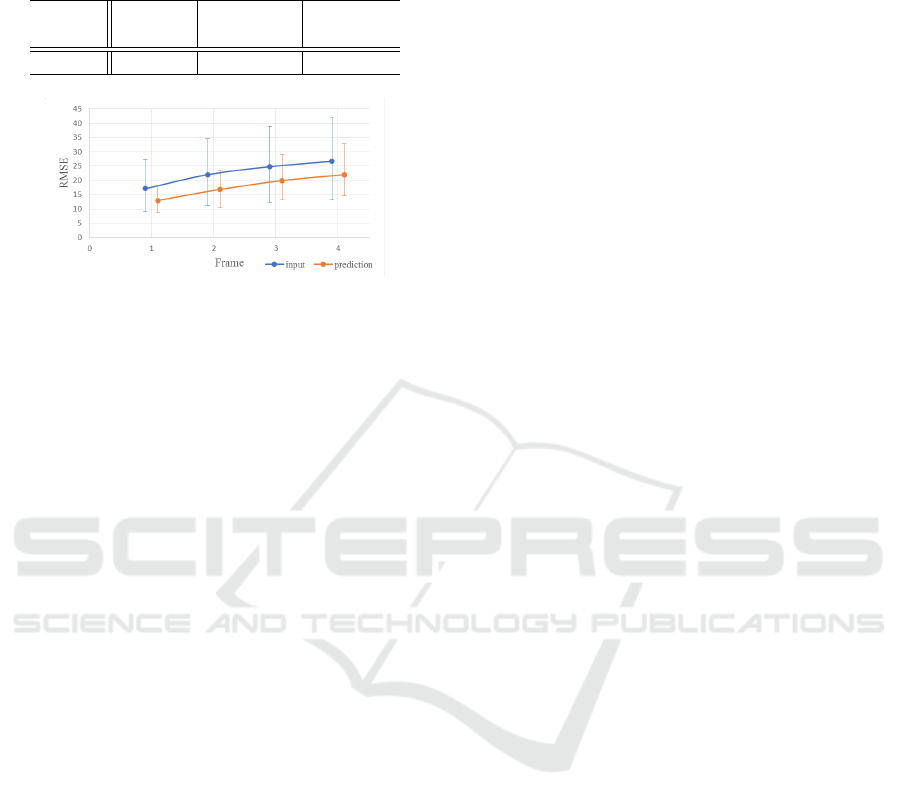
Table 1: RMSEs from the ground-truth for original input
image, predicted images without inpainting and predicted
images with inpainting.
original without predicted
inpainting image
RMSE 16.04 11.57 10.77
Figure 8: RMSE between ground-truth and predicted/input
images.
images were computed. Table 1 shows computed
RMSEs for original input images, predicted images
without image inpainting, and predicted images with
inpainting. The table shows that the RMSE decreases
with object motion prediction and image inpainting.
The results indicate that the image inpainting tech-
nique provides better results for video prediction.
We next synthesized predicted images from 1∼4
ago images, respectively. We computed RMSEs be-
tween ground-truth and the predicted images. Fig-
ure 8 shows average RMSE for each result. In this
figure, error bars for each point show the minimum
and the maximum error. For comparison, RMSE be-
tween the input images and ground-truth are shown by
an orange line. In this result, RMSEs of predicted re-
sults always are lower than ones of input images. The
results show that our proposed method can predict fu-
ture images for various images. Note that the min-
imum errors for input images and predicted images
are mostly the same since the data includes mostly
static sequences. This fact indicates that our proposed
method can predict future images for static sequences
as well as dynamic sequences.
5 CONCLUSION
In this paper, we proposed a future image prediction
method from a stereo image in a driving scene. In this
method, 3D shapes in the scene are reconstructed us-
ing the stereo method, and the reconstructed shapes
are separated into multiple objects by semantic image
segmentation. In the motion estimation of each sep-
arated object, the Kalman filter is used, and the filter
predicts the future condition of the objects. From the
conditions of the predicted objects, future images are
rendered. Furthermore, the deep image prior is ap-
plied to the predicted images to interpolate the miss-
ing areas of the images caused by occlusion, and we
finally predict the future natural images without miss-
ing areas. Several experimental results of a public
dataset show that our proposed method can predict fu-
ture images even when the input scene includes mul-
tiple objects moving independently.
REFERENCES
Cordts, M., Omran, M., Ramos, S., Rehfeld, T., Enzweiler,
M., Benenson, R., Franke, U., Roth, S., and Schiele,
B. (2016). The cityscapes dataset for semantic urban
scene understanding. In Proceedings of the IEEE con-
ference on computer vision and pattern recognition,
pages 3213–3223.
Finn, C., Goodfellow, I., and Levine, S. (2016). Unsuper-
vised learning for physical interaction through video
prediction. In Advances in Neural Information Pro-
cessing Systems (NIPS), pages 64—-72.
Hirschmuller, H. (2005). Accurate and efficient stereo pro-
cessing by semi-global matching and mutual informa-
tion. In 2005 IEEE Computer Society Conference on
Computer Vision and Pattern Recognition (CVPR’05),
volume 2, pages 807–814 vol. 2.
Isola, P., Zhu, J.-Y., Zhou, T., and Efros, A. A. (2016).
Image-to-image translation with conditional adversar-
ial networks. arxiv.
Kalman, R. E. (1960). A new approach to linear filtering
and prediction problems. ASME Journal of Basic En-
gineering.
Lowe, D. G. (2004). Distinctive image features from scale-
invariant keypoints. International journal of computer
vision, 60(2):91–110.
Sharma, S., Ansari, J. A., Murthy, J. K., and Krishna, K. M.
(2018). Beyond pixels: Leveraging geometry and
shape cues for online multi-object tracking. In 2018
IEEE International Conference on Robotics and Au-
tomation (ICRA), pages 3508–3515. IEEE.
Ulyanov, D., Vedaldi, A., and Lempitsky, V. (2018). Deep
image prior. In Proceedings of the IEEE Conference
on Computer Vision and Pattern Recognition, pages
9446–9454.
Vondrick, C., Pirsiavash, H., and Torralba, A. (2016). Gen-
erating videos with scene dynamics. In In Advances In
Neural Information Processing Systems (NIPS), pages
613––621.
Vondrick, C. and Torralba, A. (2017). Generating the future
with adversarial transformers. In Proc. IEEE Con-
ference on Computer Vision and Pattern Recognition
(CVPR).
Yu, J., Lin, Z., Yang, J., Shen, X., Lu, X., and Huang, T.
(2018). Generative image inpainting with contextual
attention. In Proc. IEEE Conference on Computer Vi-
sion and Pattern Recognition (CVPR), pages 5505–
5514.
VISAPP 2020 - 15th International Conference on Computer Vision Theory and Applications
866
