
Real-time Object Detection and Tracking in Mixed Reality using
Microsoft HoloLens
Alessandro Farasin
1,2 a
, Francesco Peciarolo
2
, Marco Grangetto
3 b
, Elena Gianaria
3
and
Paolo Garza
1
1
Department of Control and Computer Engineering, Politecnico di Torino, Corso Duca degli Abruzzi 24, 10129, Turin, Italy
2
LINKS Foundation, Via Pier Carlo Boggio 61, 10138, Turin, Italy
3
Computer Science Department, University of Torino, Via Pessinetto 12, 10149, Turin, Italy
Keywords:
Computer Vision, Mixed Reality, Microsoft Hololens, Object Detection, Object Tracking, Deep Learning,
Spatial Understanding.
Abstract:
This paper presents a mixed reality system that, using the sensors mounted on the Microsoft Hololens headset
and a cloud service, acquires and processes in real-time data to detect and track different kinds of objects and
finally superimposes geographically coherent holographic texts on the detected objects. Such a goal has been
achieved dealing with the intrinsic headset hardware limitations, by performing part of the overall computation
in a edge/cloud environment. In particular, the heavier object detection algorithms, based on Deep Neural
Networks (DNNs), are executed in the cloud. At the same time we compensate for cloud transmission and
computation latencies by running light scene detection and object tracking on board the headset. The proposed
pipeline allows meeting the real-time constraint by exploiting at the same time the power of state of art DNNs
and the potential of Microsoft Hololens. This paper presents the design choices and describes the original
algorithmic steps we devised to achieve real time tracking in mixed reality. Finally, the proposed system is
experimentally validated.
1 INTRODUCTION
In the late ’90s, Augmented Reality (AR) was popular
in the research field and its potentials and applications
in the real world were already well-known (Azuma,
1997). The idea of being able to increase our un-
derstanding of the world simply by observing some-
thing, has encouraged the research in the field, sug-
gesting lots of practical applications. Thanks to recent
technical advances, these kinds of applications are be-
coming even more popular. In this work, we exploit
a modern Head Mounted Display (HMD) equipped
with numerous kinds of sensors, to operate in Mixed
Reality (MR) (Milgram and Kishino, 1994), a more
generic meaning of AR. The goal is to retrieve infor-
mation from the external world and to detect and track
numerous kinds of objects in real-time. As output, a
label will be shown over each recognized object, with
its relative name. The entire process focuses on a
dynamic system in which both the observer and ob-
a
https://orcid.org/0000-0001-9086-8679
b
https://orcid.org/0000-0002-2709-7864
jects could move in the environment. The real-time
constraint implies the need for limiting the adoption
of complex detection algorithms (e.g. Convolutional
Neural Networks, CNNs) in favor of faster solutions,
such as feature detection/matching and tracking al-
gorithms. To avoid possible lack of accuracy while
using simpler approaches, the information extracted
by complex algorithms is properly exploited to allow
faster methods to be more effective. In the following
sections, the adopted HMD is presented along with a
brief overview of the algorithms exploited by the MR
system proposed in this paper.
1.1 Microsoft HoloLens
Microsoft HoloLens (HoloLens, ), is an HMD able
to project holograms in a real space. It has different
kinds of sensors, like RGB and depth cameras and an
Inertial Measurement Unit (IMU), that allow a real-
time perception of nearby shapes and obstacles. It is
provided with two on-board computational units: an
Intel 32-bit processor and an Holographic Processing
Unit (HPU) that manage both the operating system
Farasin, A., Peciarolo, F., Grangetto, M., Gianaria, E. and Garza, P.
Real-time Object Detection and Tracking in Mixed Reality using Microsoft HoloLens.
DOI: 10.5220/0008877901650172
In Proceedings of the 15th International Joint Conference on Computer Vision, Imaging and Computer Graphics Theory and Applications (VISIGRAPP 2020) - Volume 4: VISAPP, pages
165-172
ISBN: 978-989-758-402-2; ISSN: 2184-4321
Copyright
c
2022 by SCITEPRESS – Science and Technology Publications, Lda. All rights reserved
165

and the real-time update of displayed holograms. This
tool is able to determine its relative position with re-
spect to the real world, building in real-time a map of
the surrounding environment. Leveraging on its capa-
bilities, who wears this headset is able to move freely
in the real space, having the possibility to collect and
process different kinds of data that can be displayed
directly on the glasses. However, its computational
power is limited, and therefore it may not be able to
compute costly algorithms in real-time. To this pur-
pose, an external server provided with GPU computa-
tional capabilities should be considered. It might be
reasonable to adopt Microsoft HoloLens merely as a
mixed reality and move the entire computation part
to a cloud system. Relying on an external computa-
tional system means introducing latency. This means
that both HoloLens and the cloud environment should
cooperate to reach the right trade-off between accu-
racy and time complexity, limiting the invocations of
the cloud service.
1.2 Object Detection
In the literature, there are several methods to perform
object detection from 2D images. One of the most re-
cent and accurate technique derives from the machine
learning field (Borji et al., 2015; Han et al., 2018)
leveraging on deep Convolutional Neural Networks
(CNNs). These kinds of networks result as efficient
as complex. Among the possible networks we opted
for the fastest and most accurate ones. Three differ-
ent CNNs are used and compared: Faster Regional
Convolutional Neural (Faster R-CNN) (Ren et al.,
2015), Region-based Fully Convolutional Networks
(R-FCN) (Dai et al., 2016) and Single Shot Multibox
Detector (SSD) (Liu et al., 2016). Even if these al-
gorithms are among the fastest in their domain, they
require high computational cost to be executed. For
this reason (despite the communication delay), it is
reasonable to externalize this task to the cloud sys-
tem.
1.3 Object Tracking
By considering a dynamic environment, the object de-
tection is just the first part of the task. In real-time,
a fast methodology to follow the changing position
of several objects is needed. The tracking approach
computes the newer position of the object by com-
paring the newer frame to the last one/s (Alper Yil-
maz and Shah, 2006). It follows that no latency is
admitted in this task and hence the chosen algorithm
might have low-complexity to be executed directly
by HoloLens. Among the possible choices (Padma-
vathi S., 2014) for this purpose, the well-known and
robust Mean Shift Tracking (Wen and Cai, 2006) al-
gorithm is adopted. With an appropriate tracking
methodology, the real need to detect a new object is
limited to the situation when a new (and unknown)
object appears into the Field of View (FoV), making
the overall system more rapid and effective.
1.4 Feature Detection and Matching
To catch changes between two images or simply com-
pare two regions, several descriptors that can used.
In this specific context, possible objects could ap-
pear in the FoV while the tracking algorithm is ac-
tive. When new objects appear, a new object detec-
tion on the image must be requested. One of the
most used algorithm for this goal is Scale Invariant
Feature Transform (SIFT) (Lowe, 2004). Unfortu-
nately, this approach is too complex to be executed
in HoloLens. For that reason, we opted for the Ori-
ented FAST Rotated BRIEF (ORB) (Ethan Rublee and
Bradski, 2004) algorithm, which is a faster approach
with a comparable accuracy in our context.
2 PROPOSED METHOD
In this section, the overall system is analyzed and de-
tailed. The principal goal for this work is to deal with
the complexity of the adopted algorithms to succeed
in recognizing dynamic objects in the real-time en-
vironment. The system is meant to be fast and ac-
curate, leveraging on a high interoperability between
the cloud system and the HoloLens system (called lo-
cal system). The cloud system, provided with high
computational resources, is able to perform complex
and accurate algorithms in a short period, but suffers
from latency due to communication delays. The lo-
cal system instead is less powerful but can process
the video stream in real-time on the HPU. In detail,
the HoloLens sensors provide two kinds of informa-
tion: i) a stream of 2D images and ii) an updated mesh
of the observed surface. Furthermore, HoloLens is
able to establish the observer’s relative position and
direction. This data is preprocessed by a Detection
Policy module that decides what is the lighter action
to perform to guarantee the overall object recognition
and limit as much as possible complex computations.
Depending on the observer’s position and gaze direc-
tion and the observed scene, that module can activate
the 2D-3D Mapping, the Object Detection or the Ob-
ject Tracking modules. Finally, each recognized ob-
ject is labeled, over-imposing an hologram indicating
its name in the real space. Through the entire pro-
VISAPP 2020 - 15th International Conference on Computer Vision Theory and Applications
166

cess, several features are extracted to represent and
remind the detected objects. The whole process and
all the interactions are exhaustively described in the
Sections 2.1 and 2.2.
2.1 Cloud System
The Cloud System performs the object detection task.
Due to the complexity of the involved algorithms, it
is hosted by a server provided with one of the fastest
GPU, the NVIDIA GeForce 1080Ti. The process is
described as follows. Firstly, the Local System sends
a Detection Request, which is an HTTP request con-
taining the last captured frame, to the Cloud System .
Then, the picture is processed by the Object Detection
module that implements the algorithms presented in
Section 1.2. For this work we leveraged on pretrained
models, freely available on Tensorflow (Tensorflow, ),
that are Faster R-CNN and R-FCN with ResNet 101
and SSD with Inception ResNet V2. These models are
trained on the public dataset COCO (COCO, ).
When the Object Detection module processes a new
image, a list of Detected Objects (DOs) is returned.
Each DO is represented by:
• Bounding Box (BB): the image’s rectangle area in
which an object is identified. It consists in a cou-
ple of coordinates c
1
(x
1
, y
1
), c
2
(x
2
, y
2
), represent-
ing the upper-left and bottom-right region corners;
• Class: the most-likely class that the identified ob-
ject is supposed to belong (e.g. mouse, keyboard,
..);
• Score: the confidence with which the algorithm
associates the object to the Class. It is defined as
Score = {x|x ∈ ℜ, x ∈ [0, 1]}
To avoid false detections, we empirically defined a
minimum threshold for Score. We consider valid de-
tections only DOs having Score ≥ 0.8.
Finally, the DOs list is returned to the Local System.
2.2 Local System
The Local System runs directly on the HoloLens’
hardware. It is developed in C# by using Unity 3D
(Unity3D, ) and OpenCV (OpenCV, ). Unity 3D al-
lows mapping the information coming from the sen-
sors to a virtual environment, in which 1 meter corre-
sponds to a 1 virtual unit. This framework allows to
make a representation of the real scene, reconstruct-
ing the surfaces and tracking the HoloLens relative
position. Furthermore, every virtual object added in
the Unity scene, it is displayed as hologram in the real
space. The OpenCV framework, instead, is used to
perform image processing algorithms over the frames.
The system operates in real time, directly on the video
stream. According to several variables related to the
observed scene and the observer’s position, it evalu-
ates whether to perform a detection request or to track
the identified objects detected in the past. Further-
more, it performs the 2D-3D and 3D-2D space con-
version to map the 2D frame’s domain into the 3D
space domain (and vice-versa). This mapping is re-
quired because HoloLens provides raw data from dif-
ferent sources without mixing them: the video stream
is acquired from a 2D RGB camera, while the third
spatial dimension is computed from a central depth
camera and four gray-scale cameras placed on the
headset’s frontal sides.
In Fig.1, the local system’s flow is shown. From an
initial condition, in which the observer is steady, the
Local System takes a frame from the Frame capture
module (Fig.1, A). At startup, when previous knowl-
edge of the surrounding world cannot be exploited,
the Object detection request to server (Fig.1, G) is
triggered to request a new detection to the Cloud Sys-
tem. At this point, the Cloud System starts computing
the received frame to extract and provide the right in-
formation. Meanwhile the Local System computes,
for each acquired frame, a gray-scale histogram, dis-
cretized onto 64 bins (this information will be used in
a second step). When the Cloud System finishes the
computation, it returns a DOs list. The received data
(Receiving detected objects list module, in Fig.1, B)
is used to build the first representation of the observed
objects. First of all, it is required to map the 2D de-
tection on the camera’s space to the 3D space. This
action is performed by the 2D-3D Mapping module
(Fig.1, C) as follows:
1. Defined:
• P(x
p
, y
p
), the central pixel of a detected region:
it is a position in the frame’s space;
• C(x
c
, y
c
, z
c
), the camera position in the world’s
space, taken at the same time as the frame is
acquired
2. P(x
p
, y
p
) is transformed from the frame space, to
the world space, obtaining P
0
(x
p
, y
p
, z
p
);
3. A ray (Fig.2), starting from C(x
c
, y
c
, z
c
) and pass-
ing through P
0
(x
p
, y
p
, z
p
), is traced: the intersec-
tion between the ray and the environmental mesh
identifies a point I(x
i
, y
i
, z
i
), that is an approxima-
tion of the object’s location in the world space.
This step is easily performed by using Unity 3D
Ray Tracing and Collider functionalities.
4. Points 1 to 3 are repeated for each detected region
At each point I(x
i
, y
i
, z
i
) in the world space, the
Labels in Mixed reality module (Fig.1, D) displays a
Real-time Object Detection and Tracking in Mixed Reality using Microsoft HoloLens
167
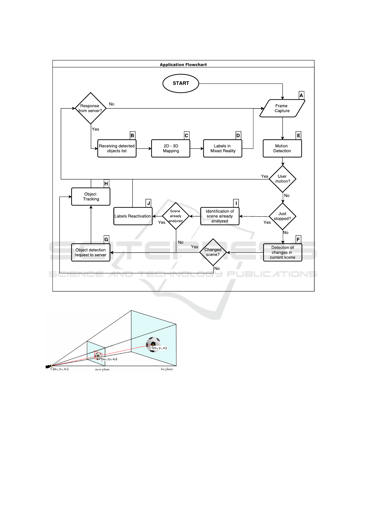
Figure 1: Local System flow diagram.
Figure 2: 2D-3D Spatial Mapping.
Unity 3D GameObject Textmesh with the respective
DO’s Class as name, as shown in Fig.3. These labels
are stored in a vector and are the internal represen-
tation of the detected objects. At this step, each ob-
ject consists in the DO’s attributes, plus the coordinate
I(x
i
, y
i
, z
i
). For each frame for which a detection is
performed, the corresponding ORB descriptor is com-
puted: this information represents the frame contents
and is stored in memory with the related recognized
objects. These data represent the geometric and visual
memory of the MR system and are exploited in the
following to avoid the analysis of frames correspond-
ing to scenes that are already known. Afterwards, a
novel frame is captured and the processing chain be-
havior depends on several policies and heuristics, the
first being based on the observer’s state. We define
observer the user that is wearing the HoloLens and
running the application. The observer is free to move
into the real world. We assume that the observer is
interested in augmenting the scene with DO informa-
tion only if her/his gaze is quite stable: for that reason,
given that the HoloLens camera streams at 30 fps, the
Local System is active only under the following con-
ditions:
1. The Maximum Translation Velocity (MTV) must
be lower than 0.27 m/s
VISAPP 2020 - 15th International Conference on Computer Vision Theory and Applications
168

2. The Maximum Angular Velocity (MAV) must be
lower than 0.25 rad/s
Overtaking these limits means deactivating the Local
System until the values lower again under the respec-
tive thresholds. These thresholds are introduced in or-
der to ensure a minimum movement tolerance when
the observer is looking at a scene. Both the current
translation and angular velocities are available from
the gyroscope and accelerometer installed on board
the HoloLens: these data are automatically mixed
with the ones acquired from the other sensors to de-
termine the relative observer’s position and frontal di-
rection.
Every novel frame is processed by the Detection
Policy module. Starting from an internal representa-
tion of previously detected objects, its task is to min-
imize the effort spent to recognize the objects in the
current frame. The possible situations that could oc-
cur are summarized as follows:
1. the observer is steady, looking in the same direc-
tion and nothing changes in the scene;
2. the observer is steady, looking in the same direc-
tion and some object is moving;
3. the observer is steady, looking in the same direc-
tion and a new object joins or leaves the scene;
4. the system, due to the observer’s movements over
the MTV and/or the MAV thresholds, was deacti-
vated and now it is reactivated.
In cases 1, 2, 3 the Detection Policy checks (through
the module ”Detection of changes in current scene”
in Fig.1, F) whether there has been any variation in
the current scene by comparing the actual frame gray-
scale histogram with the previous one. The compar-
ison is done by computing the correlation coefficient
d:
d(H
1
, H
2
) =
∑
I
(H
1
(I) − H
1
)(H
2
(I) − H
2
)
p
∑
I
(H
1
(I) − H
1
)
2
∑
I
(H
2
(I) − H
2
)
2
(1)
where H
1
(I), H
2
(I) corresponds to the value of the I-
th bin for the first and the second histograms,
H
k
=
1
N
∑
J
H
k
(J) (2)
and N is the total bins number (in our setting N = 64).
We empirically defined a threshold d
th
= 0.93. For
any d ≤ d
th
, we consider that the scene is changed:
this means that a new detection is required (Fig.1, G)
because case 3 could be happened. In the other cases
(1 and 2), a new detection request is avoided and the
Object Tracking module (Fig.1, H) is activated. The
Object Tracking module uses the mentioned Mean
Shift Tracking (MST) algorithm to track a known ob-
ject in the newly acquire frame. To this end the HSV
color space is considered. Then MFT is run using as
target the histogram of the H component of the rectan-
gular region determined by the Bounding Box (BB) of
each DO. The MST algorithm exploits the same his-
togram distance measure defined in Equation 1 and
determines the new Bounding Box coordinates c
1
and
c
2
for each DO. As final step the Object Tracking
module updates the DO coordinates in the internal
structure and triggers the 2D-3D Spatial Mapping al-
gorithm to update the world point I(x
i
, y
i
, z
i
). This
procedure is performed for each DO that was previ-
ously detected in the scene. If any object is not de-
tected by the MST algorithm, the module deactivates
the labels related to each missed object and will issue
a new detection request to the cloud server The 4-th
case needs a different treatment by the Detection Pol-
icy: the ”Identification of an already analyzed scene”
module (Fig. 1, I) is activated. After the observer has
moved, it could look at a new portion of the environ-
ment or toward a scene that was already seen and pre-
viously analyzed. That module checks this last case
by performing a Geometric Check, computed as fol-
lows:
1. Considering the camera position C(x
c
, y
c
, z
c
) as
origin, we define:
−→
v
c
, the unit vector of the ob-
server’s looking direction and
−→
v
i
, the unit vector
computed from the direction between a stored ob-
ject position I(x
i
, y
i
, z
i
) and C(x
c
, y
c
, z
c
)
2. Compute the cosine of the angle between the two
unit vectors: cosθ =
−→
v
i
·
−→
v
c
A minimum threshold d
GC
= 0.93 for the value of
cosθ is empirically defined: this threshold determines
whether the observer is looking toward an already rec-
ognized object. If none of the objects stored in mem-
ory yields cosθ ≥ d
GC
, a new detection request is per-
formed. Otherwise, one must check whether the ob-
served scene has changed from its last representation
or not. For this reason, the ORB algorithm is used
over the whole frame. The key-points computed from
the current frame are compared to the ones stored dur-
ing the last acquisition of the same scene, as shown in
Fig.4. Then, a similarity measure s is computed:
s =
| match |
max(| d
1
|, | d
2
|)
, (3)
where, | match | is the number of matching key-points
between the two frames and | d
i
| is the number of key-
points founded for the i-th descriptor. Also for this
measure, a minimum similarity s
th
= 0.4 is defined. If
both cosθ ≥ d
GC
and s ≥ s
th
, it might be asserted that
the observer is looking at a previous recognized and
unchanged scene, otherwise a new detection request
Real-time Object Detection and Tracking in Mixed Reality using Microsoft HoloLens
169
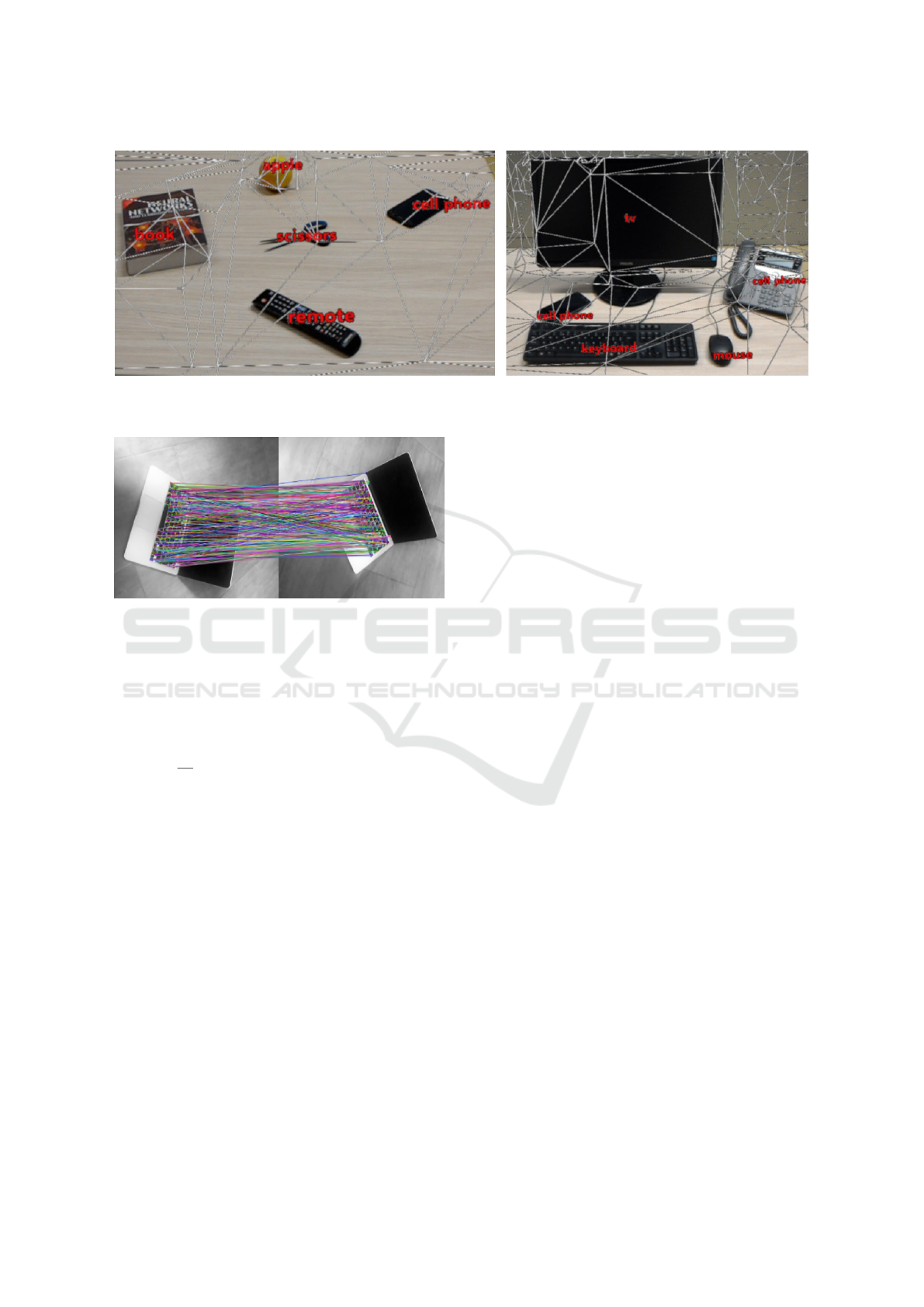
Figure 3: Recognized objects in two different scenes: each label, is placed over the respective object. The mesh, retrieved by
the sensors and computed by Unity3D, is displayed and wraps the entire visible scene.
Figure 4: ORB keypoints comparison between two frames.
is needed. In case the check succeeded, a last step
must be executed. Supposing that the user is looking
to the same scene, but from a different point of view,
the bounding boxes position must be recomputed. Re-
ferring to the 2D-3D Spatial Mapping and Fig.2, the
points C(x
c
, y
c
, z
c
) and I(x
i
, y
i
, z
i
) are known, while
P
0
(x
p
, y
p
, z
p
) must be computed as the intersection be-
tween the CI segment and the camera’s display plane.
That point is then translated into the point P(x
p
, y
p
)
in the frame’s domain and, as consequence, the coor-
dinates c
1
, c
2
are derived. This last step is named 3D-
2D Spatial Mapping and is performed by the Labels
Reactivation module (Fig.1, J) that, after this compu-
tation, over-imposes the Unity 3D Textmeshes over
the respective recognized objects.
3 EXPERIMENTS AND ANALYSIS
The principal goal for this work is to recognize ob-
jects from the real world in real-time. The following
experiments have been devised to quantify the gain
provided by the designed Detection Policy with re-
spect to a simple reference system relaying solely on
cloud frame detection requests. First of all, we de-
termined which algorithm, among the considered de-
tection algorithms, fits better our purposes. We pre-
pared a collection of 50 images about desk items and
tech products, each one containing up to five objects.
All the objects were selected from the categories that
the adopted neural networks were trained to recog-
nize. We tested each CNNs solution in the Cloud
System. We setup the cloud service on a local server
equipped with an NVIDIA GeForce 1080 Ti and con-
nected Hololens through WiFi/LAN networking. This
local server clearly simulates an ideal cloud solution
with low latency; nonetheless we will show that this
is not enough to guarantee real-time operations. Both
the Mean Average Precision (mAP) and the Execution
time are used as evaluation metrics of the cloud sys-
tem. The results are the following: (i) SSD scored
a mAP of 24 with an execution time of 77 ms; (ii)
R-FCN scored a mAP of 30 with an execution time
of 127 ms; (iii) Faster R-CNN scored a mAP of 32
with an execution time of 138 ms. On top of that, it
must be pointed out that the communication time be-
tween Local and Cloud systems is independent from
the adopted algorithm: in our settings we measured
an average round trip delay of 300 ms for server re-
quest and reply. According to the results, we chose
R-FCN as be the best balance between accuracy and
speed. The overall delayed required for a cloud ob-
ject detection is therefore about 427 ms. Then, the
Mean Shift Tracking algorithm is tested to estimate
its contribution on the execution time. For a single
object, still or moving, a single MST takes on aver-
age 43 ms. For several objects in the same picture,
the time complexity raises linearly with the number
of objects. To deal with this problem, the MST has
been implemented in a parallel fashion so as to man-
age 5 concurrent tracking threads: it means that up to
5 objects can be tracked at the same time.
In Table 1, the main execution times for all the
policies and heuristics used in our systems are shown.
VISAPP 2020 - 15th International Conference on Computer Vision Theory and Applications
170
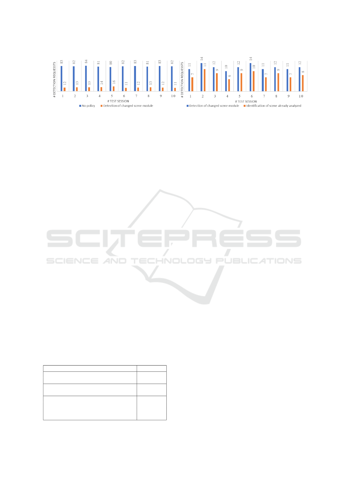
(a) (b)
Figure 5: (a.) Detection requests reduction related to the ”Detection of changes in current scene” (Fig.1, F) module; (b.)
Detection requests reduction related to the ”Identification of scene already analyzed” (Fig.1, I) module.
The obtained results show that the “Motion detection”
and the “Detection of changes in the current scene”
modules are quite fast; the slower mechanism is rep-
resented by the module “Identification of an already
analyzed scene”, that in any case introduces a latency
of about 243 ms that is much better than the cloud
system delay that is approximately 427 ms. The ORB
algorithm is performed both in this module and after
every detection request: even if performing this action
is time-costly, the retrieved information could avoid a
new detection request every time the observer looks
again to an already seen location. To test the impact
of the different checks and policies, a scene with 5
objects has been set up. The evaluation consisted in
two different tests, repeated ten times, each one by a
different user.
The first test is related to the “Detection of
changes in the current scene” module. Standing still,
in front of the scene, the number of cloud detection
requests performed in 60 seconds is logged. As a ref-
erence system we consider the case when we disable
all the designed policies, i.e. a new cloud detection
request is issued as soon as a reply from the previ-
ous one is received. Then, we repeat the same exper-
iment a second time by activating the “Detection of
changes” module. The results shown in Fig.5.a con-
firm that the designed heuristic yields a significant re-
duction of detection requests that lower from 82 re-
quests per minute (rpm) to an average of 13 rpm in
the second case.
A second test is performed on the ”Identification of an
Table 1: Execution time for checks and policy modules.
Module Exec. time
Motion detection:
< 1 ms
MTV and MAV computation
Detection of changes in the current scene:
13 ms
Frame’s gray-scale histogram
Ident. of already analyzed scene :
Geometric Check < 1 ms
ORB computation 197 ms
Similarity measure (ORB key-points) 46 ms
already analyzed scene” module: in this case, another
similar scene with 5 objects was prepared. After a
first detection of the new test environment, each tester
gazed alternatively 10 times the two scenes. The com-
parison is evaluated on the sent requests, having just
the “Detection of changes” module activated. The
results provide in Fig.5.b show further improvement
of the proposed technique. All the users experiment-
ing the proposed MR system confirmed the benefi-
cial effect of the designed heuristics: in particular,
during the experiments, the users did not evidence a
wrong or badly aligned MR labels. More importantly
the 10 users confirmed that the system works in real-
time with labels correctly refreshed. According to the
previous results, the Local System plays an impor-
tant role in limiting the number of detection requests:
both MST and Detection Policy algorithms perform
faster than the delay induced by the communication
between Local and Cloud systems. These modules
improve significantly the performance and the respon-
siveness of the application. In the best case, in which
the observer is statically looking at a scene, the Local
System can process up to about 18 fps by the activa-
tion of MST and the “Detection of changes for cur-
rent scene” module: this is a significant improvement
compared with the limit of 1.5 fps imposed by a sim-
ple use of cloud detection only.
4 CONCLUSIONS
This paper presented a mixed reality system, able to
detect and track generic objects in a dynamic envi-
ronment in real-time. That system dealt with com-
plexity problems of detection algorithms and limited
computational resources by combining the HoloLens’
processor with a cloud system equipped with high
computational capabilities. The Cloud System was
in charge to process R-FCN algorithm to detect ob-
jects from a frame with the right compromise between
speed and accuracy. HoloLens runs the Local Sys-
tem, which performs objects tracking, features extrac-
Real-time Object Detection and Tracking in Mixed Reality using Microsoft HoloLens
171

tion and spatial mapping tasks. Several policies and
heuristics are introduced in the Local System in order
to limit the detection requests to the Cloud System.
Limiting the external requests implied an increment
of about 12 times the total frames per second pro-
cessed (in the best case), without altering the overall
system’s accuracy.
REFERENCES
Alper Yilmaz, O. J. and Shah, M. (2006). Object Tracking:
A Survey.
Azuma, R. T. (1997). A survey of augmented reality.
Presence: Teleoperators and virtual environments,
6(4):355–385.
Borji, A., Cheng, M.-M., Jiang, H., and Li, J. (2015).
Salient object detection: A benchmark. IEEE trans-
actions on image processing, 24(12):5706–5722.
COCO. http://cocodataset.org/.
Dai, J., Li, Y., He, K., and Sun, J. (2016). R-fcn: Object de-
tection via region-based fully convolutional networks.
In Advances in neural information processing sys-
tems, pages 379–387.
Ethan Rublee, Vincent Rabaud, K. K. and Bradski, G.
(2004). Orb: an efficient alternative to sift or surf.
Han, J., Zhang, D., Cheng, G., Liu, N., and Xu, D. (2018).
Advanced deep-learning techniques for salient and
category-specific object detection: a survey. IEEE
Signal Processing Magazine, 35(1):84–100.
HoloLens, M. https://www.microsoft.com/hololens.
Liu, W., Anguelov, D., Erhan, D., Szegedy, C., Reed, S.,
Fu, C.-Y., and Berg, A. C. (2016). Ssd: Single shot
multibox detector. In European conference on com-
puter vision, pages 21–37. Springer.
Lowe, D. G. (2004). Distinctive image features from scale-
invariant keypoints.
Milgram, P. and Kishino, F. (1994). A taxonomy of mixed
reality visual displays.
OpenCV. https://opencv.org//.
Padmavathi S., D. S. (2014). Survey on tracking algorithms.
International Journal of Engineering Research and
Technology (IJERT).
Ren, S., He, K., Girshick, R., and Sun, J. (2015). Faster
r-cnn: Towards real-time object detection with region
proposal networks. In Advances in neural information
processing systems, pages 91–99.
Tensorflow. https://www.tensorflow.org/.
Unity3D. https://unity3d.com/.
Wen, Z.-Q. and Cai, Z.-X. (2006). Mean shift algorithm
and its application in tracking of objects. In Machine
Learning and Cybernetics, 2006 International Con-
ference on, pages 4024–4028. IEEE.
VISAPP 2020 - 15th International Conference on Computer Vision Theory and Applications
172
