
Implementation PID in Coupled Two Tank Liquid Level Control using
Ziegler-Nichols and Routh Locus Method
M. Imaduddin
1
, M. Awfa Nawfal Kamil
1
, Syaral Hafizh Putra
1
, Riswanda Imawan
1
, Anbar T. N.
Zahra
1
, Reza Fauzi Iskandar
1
, Nurwulan Fitriyanti
1
1
Engineering Physics, Telkom University
nurwulanf}@telkomuniversity.ac.id
Keywords:
Ziegler-Nichols, Routh-Locus, PID.
Abstract:
In this paper, we investigated liquid level controlling of coupled two tank SISO using PID controller. Zigler-
Nichols (ZN) method and Routh-Locus method were compared. Three setpoint 2cm,3cm,4cm was used to
show each method respond and diffrence. Output signal, error signal, and control signal of each method was
analyzed. Transient parameters consist of time constant, rise time, and steady state value was demonstrated
for each method. Then, those value were compared to simulation result. It results Routh-Locus method have
prefer control respond.
1 INTRODUCTION
Proportional Integral Derivative (PID) is one of pop-
ular control types in industry. (Feng, 2018) used
PID for controlling boom, arm, bucket of hydrolic
excavator. Parameters of PID were determined by
Ziegler - Nichols (ZN) method. Priyanka and Mah-
eswari (Priyanka et al., 2018) controlled flow rate in
oil pipeline transportation with PID controller. (Ya-
dav et al., 2016) designed control system of the ball
position of the magnetic levitation system (MLS) with
parameter of PID. PID also was utilized to control
temperature in bioreactor(Pachauri et al., 2017). El-
samahy and Shamseldin (El-Samahy and Shamseldin,
2018) was using PID for controlling speed of brush-
less DC motor regardless of load disturbance.
One of PID control in industry is for controlling
liquid level . Liquid level control is commonly used
in the water purification industry, such as the pharma-
ceutical, biochemical, food and beverage manufactur-
ing industries (Bas¸c¸i and Derdiyok, 2016). More than
80 % of the industry automatically used proporsional-
integral-derivatif PID controllers. because PID is eas-
ier to manage, cheaper and easier to implement(Roy
et al., 2017). Liquid level control is widely imple-
mented in industries such as water level controlling in
nuclear steam generator, daerator, and coupled liquid
two tank system (Tan, 2011) (Liang, 2018).
Coupled two tank system is one of most plant
being investigated in control study. (Roy and Roy,
2016) controlled water level of one tank to be con-
stant as another tank level is randomly varying. (Bas¸c¸i
and Derdiyok, 2016) developed adaptive fuzzy algo-
rithm to control liquid level in coupled tank. Pa-
rameter of fuzzy is identified online. They showed
the result is better compared to PI controller. (Roy
et al., 2017) was using fractional order PI and PD
to control single input single output (SISO) coupled
two tank.(Pan et al., 2005) To control a two-level and
level system a backstepping controller and an adap-
tive backstepping controller are needed. For an expo-
nential/asymptotic stable response using a Lyapunov
machine. (Ramli, 2009) For adaptive tuning to ad-
just neural network weights and fine tuning controller
parameters can use the particle swarm optimization
(PSO) technique.They designed approach for control-
ling liquid levels of coupled tank Two-Input Two-
Output (TITO) system by using hybrid PI-Neural Net-
work (hybrid PI-NN) controllers. (Gouta et al., 2015)
Designed a model- based step-back controller com-
bined with high gain for two tank fluid level systems.
Parameters of PID could be tuned by artificial intel-
ligent algorithm like fuzzy, neural network, genetic
algorithm, BAT algorithm, neuro fuzzy, IT2FNNC as
reseachers did in (Liang, 2011) (Lian et al., 1998) (Li
et al., 2008) (Katal et al., 2014). In this paper, we
investigated liquid level controlling of coupled two
tank SISO using PID controller. Zigler Nichols (ZN)
method and routh locus method were compared.
Your paper will be part of the conference proceedings
274
Imaduddin, M., Kamil, M., Putra, S., Imawan, R., Zahra, A., Iskandar, R. and Fitriyanti, N.
Implementation PID in Coupled Two Tank Liquid Level Control using Ziegler-Nichols and Routh Locus Method.
DOI: 10.5220/0009882602740279
In Proceedings of the 2nd International Conference on Applied Science, Engineering and Social Sciences (ICASESS 2019), pages 274-279
ISBN: 978-989-758-452-7
Copyright
c
2020 by SCITEPRESS – Science and Technology Publications, Lda. All rights reserved
therefore we ask that authors follow the guidelines ex-
plained in this example in order to achieve the highest
quality possible.
Be advised that papers in a technically unsuitable
form will be returned for retyping. After returned the
manuscript must be appropriately modified.
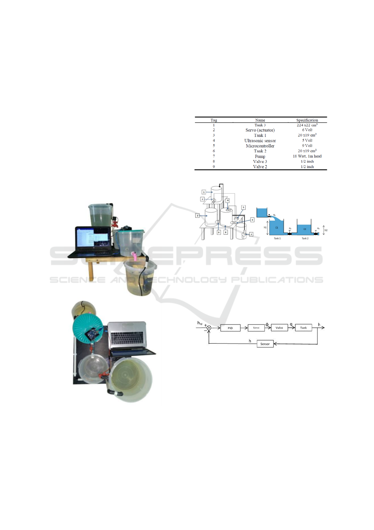
2 SYSTEM DESIGN
The system was a single input and single output
(SISO). Beside that, there are two extra tanks were
used for supporting system works. Real system is
demonstrated on figure 1. Figure 2 shows the con-
struction of coupled two tank system. The input was
flow rate that was supplied from tank on the top side.
Water that exit from system was collected in tank be-
low it then directly pumped up to tank on top side.
Figure 1: System design.
Components used in this system involved two
20x19 cm3 main tanks, one 20x19 cm3 discharge
tank, one 24x22 cm3 top tank as container. Figure
2 shows these component in detail. Tank 1 and tank 2
was linked by 0.5 inch pipe. This pipe has resistance
R1 that handly maintained by globe valve installed on
it. R1 in this case was maintained constant. The outlet
of tank 2 was coupled by 90o valve that has resistance
R2. Similar with R1, R2 was maintaned constant. 1 m
head pump was located inside discharge tank to pump
water to tank 3.
Table 1: Component and Specification.
Figure 2: Construction and terminology of coupled water
tank system (a) overall system (b) coupled two tank model.
Tank 2 water level h2 was sensed by ultrasonic
sensor mounted on tank seal. H2 was compared with
set point then error signal was appeared. Figure 3
shows a control diagram. Error signal generated con-
trol signal with PID function. Control signal actuated
servo to move as error signal appearance. Flowrate
was increasing proportional with servo degree.
Figure 3: Control diagram.
In this system, flowrate q1 is depend on servo mo-
tor position. Figure 3 demonstrates coupled two tank
system. Maximum flow rate q1 was determined by
top tank level. But, top tank level was changing along
with set point changing. Higher level set point, lower
top tank level. In equilibrium, q1 is equal to q3. Top
tank volume was decreasing, spreading in tank 1 and
tank 2. Since this problem of depending flowrate to
set point, relationship servo motor position in degree
with h1 (cm) was non linear on all control range. To
tackle this problem, control range (set point range)
should be cut off to force linearity between servo mo-
tor position with h1.
Implementation PID in Coupled Two Tank Liquid Level Control using Ziegler-Nichols and Routh Locus Method
275
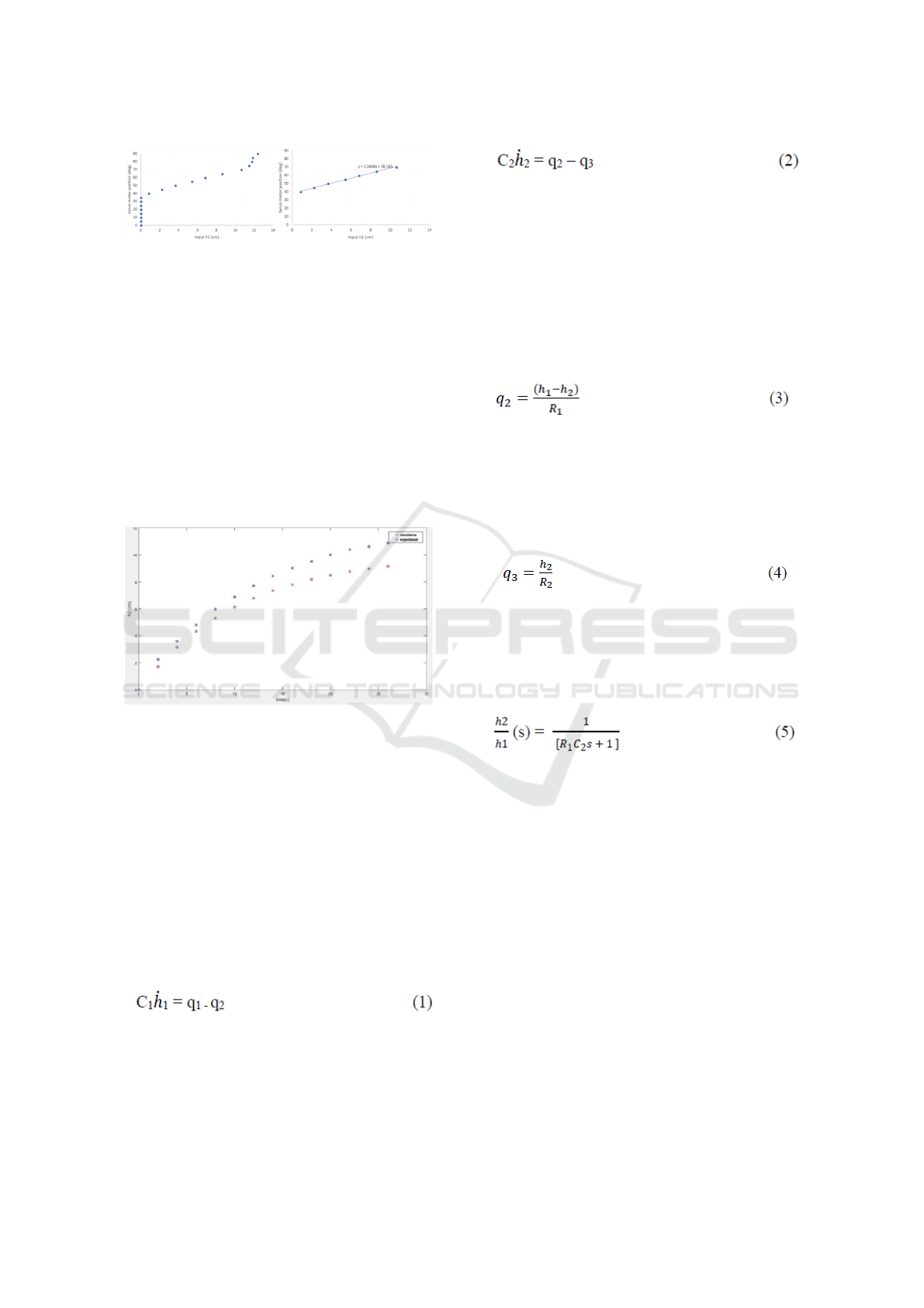
Figure 4: Servo motor position to input h1 characterization
(a) original (b) after set point cutting off.
Figure 4a shows non-linearity for all output range.
From 0o-35o servo motor position, system still did
not give any such respond caused by too small flow
rate q1. System respond started on 40o, but appar-
ently for servo motor position more than 70o it be-
came non-linear. Range of linerity in this system was
from 40o-70o servo position or 2-10 cm. Figure
4b shows range linearity of this system. In this pa-
per, system was analyzed in 2-4 cm set point for each
method (RL and ZN). Effect of non-linearity flow rate
q1 is an obstacle of each method to show their respond
in control signal producing.
Figure 5: Validation model with step input signal.
Output from this system is level in tank 2 (h2) and
the input is level tank 1 (h1). Tank 1 water level (h1)
was characterized with servo 90o motor position as
actuator validation. HCSR04 is ultrasonic sensor that
used in output with accuracy 3-5 mm and controlled
by microcontroller. Transfer function can be derived
from tank equation and valve equation.
On tank 1, inlet water flow was q1 from top tank
(supply tank). Outlet water flow was q2. Tank 1 has
capacitance C1 and head h1. Flow rate changing (q1-
q2) is proportional with rate of tank 1 volume chang-
ing that is C1h 1. Equation (1) is describing this pro-
cess.
On tank 2, inlet water flow was q2 from tank1.
Outlet water flow was q3. Tank 2 has capacitance C2
and head h2. Flow rate changing (q2-q3) is propor-
tional with rate of tank 2 volume changing that is C1h
1. Equation (2) is describing this process.
Q2 is water flow rate caused by different head or
level between tank 1 and tank 2. When water level
tank 1 is higher than water level tank 2, water flows
from tank 1 to tank 2 as consequence water flow rate
has positive number. Water flow rate is depend on re-
sistance of valve 1 (R1). Since in this case, resistance
was dominant, inertance effect on pipe 1 was negli-
gible. Equation 3 shows relationship between q2, h1,
h2, and R1.
Similar with q2, q3 is water flow rate out from
tank 2. This water flow rate is proportional to head
or level tank2 and reciprocal to valve 2 resistance
(R2). Inertance effect also was negligible. Equation 4
shows this process.
In this system, resistance on valve 2 is very
large compared to resistance on valve 1. Taking
(1)(2)(3)(4) for R1 >> R2, function transfer h2 to h1
was determined.
Transfer function (5) had been validated that
shows on figure 5. From validation model, time con-
stant, settling time, and precise transfer function was
generated.
Varible R1 and C2 should be analyzed to get full
function transfer (5). But the way to get precise these
variable needs accurately time consuming many ex-
periments. Alternatively, value R1 and C2 could be
analyzed with simple open loop experiment. These
experiment also would be used for Zigler-Nichols
PID parameters tuning so it will minimize time spent.
From equation (5), it seen R1C1 apparently time con-
stant of transfer function. With analyzing respond h2
to step signal h1 and getting time constant from that
experiment, value R1C1 would simply get without an-
alyze separately R1 and C1 in diffrent way of long
time experiment. Figure 5 is comparison validation
model with experimental data. It shows average error
between model and experimen was 14%. This error
ICASESS 2019 - International Conference on Applied Science, Engineering and Social Science
276
was caused by dificulty of generating purely step sig-
nal of input h1 manually. Equation (6) shows the final
result of open loop function transfer.
Kp, Ti, Td with Routh locus can be obtained by
deriving Gcl equation and taking τ
i
= 2τ, τ
d
=
1
2
τ and
τ value from Table 2.
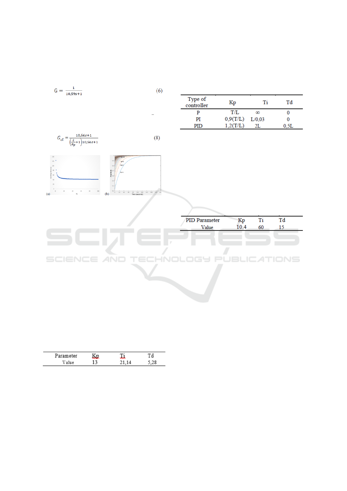
Figure 6: Kp testing graph with routh locus method (a) set-
tling time versus Kp (b) transient respong for each Kp.
Equation (8) is PID close loop function transfer
with RL method. As seen from (8), system respond
depends on value of Kp. In level coupled two tank
system, to reach a set point from such level is time
consuming as bigger tank or smaller flowrate input.
The value of Kp should be chosen to minimize time
consuming. Time settling (5%) is one transient vari-
able that could show how fast system to reach steady
state condition. Value of Kp was simulated to look its
effect with time settling. Figure 6a shows the result
of simulation with step input. When zero Kp, system
was too slow respond. As value Kp riser, time set-
tling downed then get saturation. As seen from figure
6b, for high Kp, system respond approch to critically
damped. When Kp = 13 settling time was 47.7 s and it
started asymptotic. Then Kp=13 was chosen. Ti and
Td was generated from it. Table 3 shows PID param-
eters with routh locus method.
Table 3: Component and Specification.
With routh locus method, we could adjust PID pa-
rameters (Kp, Ki, Kd) as we desire. Time settling and
others transient parameter could be chosen with an-
alyzing PID parameters. But sometimes, analyzing
PID parameters with routh locus method is compli-
cated as higher order system. When transfer func-
tion of system cannnot be gotten , or difficult to be
gotten (need long time analyses) routh locus method
couldn’t be implemented. Ziegler-Nichols method is
easy and fast method to get PID parameters.
Table 4: PID parameter tuning with Ziegler-Nichols
1.
Ziegler-Nichols method was first introduced by J.
G. Ziegler and N. B. Nichols on 1942 (Ziegler and
Nichols, 1942). With these method, it does not need
purely matematical approach to get PID parameters as
routh locus method. By experiment, getting lag time
(L) or delay and time constant (T), PID parameters
could be tuned with Ziegler-Nichols rule directly (see
table 4). In this system L=0.5 and T=12. Table 5
shows PID parameters with ZN method.
Table 5: PID parameters with Ziegler-Nichols
method.
Apparently Ziegler-Nichols method shown fast
and simple. But it needs experiment to get PID pa-
rameters. For fast respond system, it needs varying
Kp experiment make it relative time consuming. In
this system, since high resistance on valve 2, mini-
mum time to reach higher level on tank 2 was faster
than to get lower level. Since this diffrence time, ob-
vously, high overshoot was avoided. Ziegler-Nichols
method and routh locus method were compared to
show each respond advantages and disadvantages.
3 RESULT AND DISCUSSION
Level sensor read up and down value of ouput, not
smooth graphic like simulation result. This anomaly
points were caused by water ripples in tank 2. Water
initially came out from top control valve. Water fell
in tank 1 with such height and directly faced water
surface of tank 2. This direct contant bettween wa-
ter from top valve and water surface of tank 1 caused
ripples. Water ripple in tank 1 affect water ripple in
tank2. Water ripple in tank 2 cause anomaly read-
ing on ultrasonic level sensor. To minimize this rip-
ples, we implemented pipe from inlet valve to deep
of tank 2. With this method, water ripples could be
minimized.
Implementation PID in Coupled Two Tank Liquid Level Control using Ziegler-Nichols and Routh Locus Method
277

Ideally, with PID parameters on table 3 and table
5, each method (RL and ZN) will create respond to
exactly setpoint (0% steady state error). Routh locus
method and Ziegler-Nicols method shall have small
diffrence in rise time value. Routh locus will be faster
to reach steady state than Ziegler-Nichols method.
But in our experiment those are not exactly accurate.
Figure 7 shows dinamics respond of each method with
4 cm set point. Figure 7 a shows output versus time
graphic with Ziegler-Nicols. In other hand, figure 7
a shows output versus time graphic with Routh lo-
cus method. Visually, from these graphic, routh lo-
cus method has better respond than Ziegler-Nichols.
It looks, Ziegler-Nichols method gives oscillation re-
spond. This oscillation is not our desirement because
it will make PID control generating control signal up
and down over and over. It is energy consuming, de-
creasing life time of actuator (servo motor), initiat-
ing servo motor bolt joint damage. This oscillation
could be looked as water ripples on tank 2. With this
view, it looks clearly, Ziegler-Nichols has higher wa-
ter ripples than Routh locus method. We did experi-
ment with 3 setpoint: 2 cm, 3cm, and 4 cm and each
method gave result similar water ripples level on each
set point. Average water ripples of Ziegler-Nichols
method and Routh locus method are 0,36 cm and 0,21
cm respectively. From water ripples view, Routh lo-
cus method has more desired method. Figure 7 c and
7 d shows error versus time graphic for setpoint 4 cm
with Ziegler-Nichols method and routh locus method
respectively. These graphic have strong relationship
with output-time graphic on figure 7a and 7b. Error
signal decreases along with output signal approach
to set point. Oscillation output respond on Ziegler-
Nichols method also make error signal oscillation.
Figure 7: Output to setpoint 4 cm (a) with routh locus
method (b) with zigler nichols method. Error to setpoint
4 cm (c) with routh locus method (d) with zigler nichols
method.
Error signal will make PID generating control sig-
nal to operate actuator. In this case, actuator was
servo motor 90o. Figure 8 shows control signal – time
for set point 4 cm water level h2. As discussion ear-
lier, Ziegler-Nichols method generates relatively high
water ripples or oscillation in error signal. This os-
cillation have strong relationship with control signal
oscillation on figure 8a. Comparing figure 8a and fig-
ure 8b, Routh locus has smoother control signal than
Ziegler-Nichols. Up and down control signal on fig-
ure 8a in long time period have tendency to risk bolt
joint of actuator (servo motor).
This bolt joint attach servo motor to tank 3. If
servo motor move over and over in extreme oscilla-
tion, bolt joint would get high oscillation torque. It
would make bolt hole falling into fatigue. In sev-
eral application, bolt joint fatigue is very dangerous
and avoided. Reference (Ziegler and Nichols, 1942)
show bolt joint fatigue damage. In control signal point
of view, Routh locus method is prefer than Ziegler-
Nichols.
Figure 8: Control signal to setpoint 4 cm (a) with routh
locus method (b) with zigler nichols method.
To compare Ziegler-Nichols method and Routh lo-
cus method, we did several experiment consist of 3
set point for each method. The result in each set
point have been tabulated on table 6. Futhermore,
experiment result was compared with simulation re-
sult. Rise time in simulation result should be the same
in all set point that is 26,8s and 23s for Routh locus
method and Ziegler-Nichols respectively. It is also
valid for other transient parameters. They should be
the same in all set point. But it shows value difference
between experiment and simulation result. These dif-
ference was happened caused by many things of tools
limited. Motion of tools platform (wood table) will
cause water ripples and error sensor reading. Level
sensor has limited accuracy and precission will cause
output looks oscillation or changing eventhough ac-
tually it doesnt. This error appears primary because
small setpoint we used for sensor spesification. Gen-
erally, from table 6, it shows Routh locus method have
faster respond than Ziegler-Nichols. Also, Routh-
locus method have smaller steady state error than
Ziegler-Nichols. As summary, Routh- Locus have
better spessification of control respond.
Table 6: System respond.
ICASESS 2019 - International Conference on Applied Science, Engineering and Social Science
278

4 CONCLUSION
For coupled two tank level control, tuning PID param-
eter with Ziegler-Nichols method is fast without long
analitics formulation but respond system cannot be
adjust like we want. With RL method, system respond
is faster, smaller steadt state error, smaller water rip-
ples, smoother respond. PID parameters of Routh lo-
cus method could be adjusted like we want so it made
RL method powerful, more safety, more smooth, and
more stable.
REFERENCES
Bas¸c¸i, A. and Derdiyok, A. (2016). Implementation of an
adaptive fuzzy compensator for coupled tank liquid
level control system. Measurement, 91:12–18.
El-Samahy, A. and Shamseldin, M. (2018). rushless dc mo-
tor tracking control using self-tuning fuzzy pid control
and model reference adaptive control. Ain Shams En-
gineering Journal, 9(3):341–352.
Feng, H. (2018). Robotic excavator trajectory control us-
ing an improved ga based pid controller. Mechanical
Systems and Signal Processing, 105:153–168.
Gouta, H., Said, S., Barhoumi, N., and M’Sahli, F. (2015).
Observer-based backstepping controller for a state-
coupled two-tank system. IETE Journal of Research,
61(3):259–268.
Katal, N., Kumar, P., and Narayan, S. (2014). Optimal pid
controller for coupled-tank liquid-level control system
using bat algorithm. In 2014 International Conference
on Power, Control and Embedded Systems (ICPCES,
page 1–4.
Li, C., Yi, J., and Zhao, D. (2008). Interval type-2 fuzzy
neural network controller (IT2FNNC) and its appli-
cation to a coupled-tank liquid-level control system.
3rd International Conference on Innovative Comput-
ing Information and Control.
Lian, S., Marzuki, K., and Rubiyah, Y. (1998). Tuning of
a neuro-fuzzy controller by genetic algorithms with
an application to a coupled-tank liquid-level control
system. Engineering Applications of Artificial Intelli-
gence, 11(4):517–529.
Liang, G. (2018). Deaerator water level control based on
neuron intelligent control by fieldbus intelligent con-
trol network. In 2008 IEEE International Conference
on Networking, Sensing and Control, page 195–200.
Liang, L. (2011). The application of fuzzy pid controller in
coupled-tank liquid-level control system. In 2011 In-
ternational Conference on Electronics, Communica-
tions and Control (Icecc, page 2894–2897.
Pachauri, N., Rani, A., and Singh, V. (2017). Bioreactor
temperature control using modified fractional order
imc-pid for ethanol production. chemical engineering
research and design, 122:97–112.
Pan, H., Wong, H., Kapila, V., and Queiroz, M. (2005). Ex-
perimental validation of a nonlinear backstepping liq-
uid level controller for a state coupled two tank sys-
tem. Control Engineering Practice, 13(1):27–40.
Priyanka, E., Maheswari, C., and Thangavel, S. (2018). On-
line monitoring and control of flow rate in oil pipelines
transportation system by using plc based fuzzy-pid
controller. flow measurement and instrumentation.
Ramli, M. (2009). Improved coupled tank liquid lev-
els system based on swarm adaptive tuning of hy-
brid proportional-integral neural network controller.
American J. of Engineering and Applied Sciences,
2(4):669–675.
Roy, P., Kar, B., and Roy, B. (2017). Fractional order pi-pd
control of liquid level in coupled two tank system and
its experimental validation. Asian Journal of Control,
19(5):1699–1709.
Roy, P. and Roy, B. (2016). Fractional order pi control ap-
plied to level control in coupled two tank mimo sys-
tem with experimental validation. Control Engineer-
ing Practice, 48:119–135.
Tan, W. (2011). Water level control for a nuclear
steam generator. Nuclear Engineering and Design,
241(5):1873–1880.
Yadav, S., Verma, S., and Nagar, S. (2016). Optimized
pid controller for magnetic levitation system. IFAC-
PapersOnLine, 49(1):778–782.
Ziegler, J. and Nichols, N. (1942). Optimum settings for
automatic controllers. trans. ASME, 64(11).
Implementation PID in Coupled Two Tank Liquid Level Control using Ziegler-Nichols and Routh Locus Method
279
