
A Vehicle Braking System based on 3D Camera
Sonki Prasetya
1,2
, Hasvienda M. Ridlwan
1
, Idrus Assagaf
1
, Muslimin
1
, Mohammad Adhitya
2
,
Danardono A. Sumarsono
2
1
Mechanical Engineering Department of Politeknik Negeri Jakarta
2
Mechanical Engineering Department, Engineering Faculty of Universitas Indonesia
Keywords: Braking, 3D Camera, object classification.
Abstract: One of important feature in a vehicle is the braking system. It is made for a safety device during driving this
also included for operation of a heavy vehicle namely a forklift. However, forklift accident has a higher
annually. The human factor is considered the main cause of the accident due to the unconsciousness
condition while driving. This investigation emphases on applying an intelligent device that can classify
objects as well as measure distances in front of an object to decide the braking action. The method of this
study process pictures derived from a stereo camera that employed a neural network algorithm. A mini-
computer is implanted with the algorithm can classify the objects in front of vehicles. Later on, the two sets
of camera position that capture images that can be used to calculate the distance of objects from the camera.
Furthermore, process of decelerating signal depends on the distance. The categorization and the distance
measurement needs around 300 ms. Moreover, braking action is decided upon the intensity. The higher
value means hard stopping meanwhile lower value represents the slow stopping.
1 INTRODUCTION
One of an important human inventions is a
vehicle particularly a car in the 19
th
century. This
invention is used for moving a human from one to
another place. People also use vehicle for
transporting heavy objects during their work
especially in a factory.
However, accident can happen during the work.
The data shows that more than 20,000 forklift
accidents happened annually (Industries, 2019). The
most common cause of the accident is the operator
inattention (California, 2018). This can happen due
to fatigues, distractions and carelessness.
Artificial intelligent methods are now common to
be used in any area of human activities. Camera
utilizations for helping human work to represent the
eye of machines are widely applied (Fleming,
Allison, Yan, Lot, & Stanton, 2019; García, Prioletti,
Cerri, & Broggi, 2018; Nguyen & Brilakis, 2018).
Studies of the camera application in heavy
equipment vehicle have been done by several
researchers. A forklift with the visual guidance is
researched by Seelinger in 2006 (Seelinger & Yoder,
2006). Other work done by Bellomo equipped the
forklift with a camera to estimate the pallet position
using camera and LIDAR (Bellomo et al., 2009).
Moreover, a study done by Irawan (Irawan et al.,
2018) added camera for alignment. However,
forklift researches normally focuses on pallet
carrying.
Therefore, a device to assist a forklift operator to
improve the safety during driving is the objective of
this study. The purpose of the investigation is to
implement the stereo (3D) camera to detect and
measure the distance of the objects. Thus, it can
produce the braking action.
This paper describes the usage of artificial
intelligent for generating a braking intensity by
means of an electrical signal to drive the braking
actuator. As an additional, this intelligent braking
assistance for forklift driver can be further
implemented to an autonomous vehicle.
2 METHODOLOGY
There are two main stages to achieve the
objective of the investigation. The first is to detect
an object by the camera (categorizing and measuring
distance). The second is to generate braking
intensity. The beginning of the step is detecting an
38
Prasetya, S., Ridlwan, H., Assagaf, I., Muslimin, ., Adhitya, M. and Sumarsono, D.
A Vehicle Braking System based on 3D Camera.
DOI: 10.5220/0009871600002905
In Proceedings of the 8th Annual Southeast Asian International Seminar (ASAIS 2019), pages 38-41
ISBN: 978-989-758-468-8
Copyright
c
2022 by SCITEPRESS – Science and Technology Publications, Lda. All rights reserved
object. Utilizing a stereo camera requires focal
length, point coordinates, radial and tangential
distortion factor. Kinect (type of the camera) is an
apparatus produced by Microsoft that provides two
cameras incorporated into one module. It is normally
use for gaming purposes on video game or Microsoft
Windows PC. However, this also utilized for serious
purpose applications such as in educational (Xu et
al., 2019) and medical sciences (Oh, Kuenze,
Jacopetti, Signorile, & Eltoukhy, 2018).
The method of identifying an object is obtained
by Convolutional Neural Network (CNN). This
Neural Network method follows the human brain
works. There are variants of CNN implemented.
However, a type of feed forward is employed for
this investigation. This technique requires several
layer (Huang et al., 2018; Jalali, Mallipeddi, & Lee,
2017) namely Convolution layer, Rectified Linear
Unit (ReLU), Pooling and Fully Connected layer.
Numbers of layer follow the rule:
(1)
where
,
is k
th
row and l
th
column of the pixel,
is the function,
,
is the filter position weight,
,
is the pixel of point k and l of input image, and
is bias filter respectively. The PxQ is the size of
the kernel (smallest matrix of an image). The
learning and optimization process generate values of
,
and
.
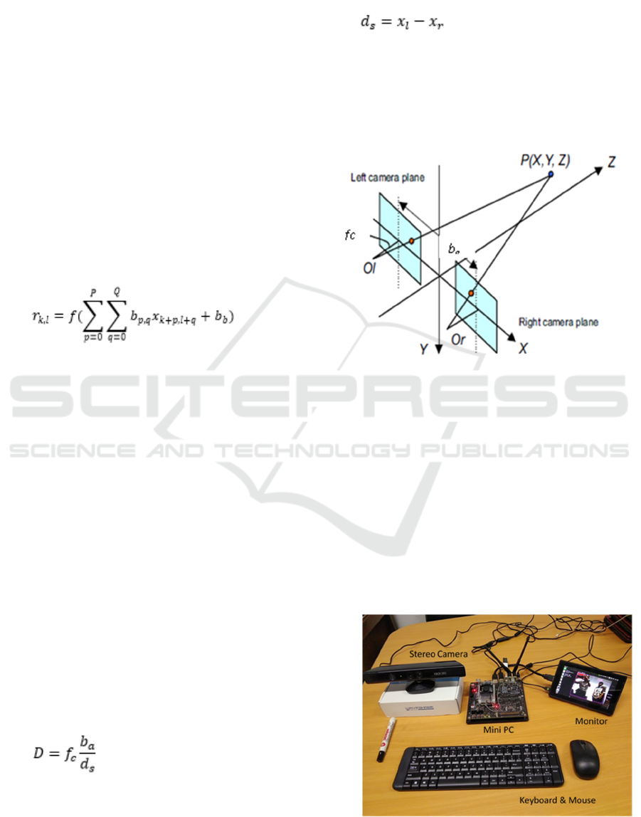
The method of stereo camera has been used for
several application areas (Boldt, Williams, Rooper,
Towler, & Gauthier, 2018; Chi, Yu, & Pan, 2018;
Murmu, Chakraborty, & Nandi, 2019; Williams,
Rooper, De Robertis, Levine, & Towler, 2018) . In
order to obtain the estimated depth between an
object with the camera, it uses a triangular formula.
The calculation of the depth (D) is described as
follow (Hu, Lamosa, & Uchimura, 2005)
(2)
where,
is the focal length of the camera,
is
the base of triangle,
is disparity respectively. The
base is a distance between the left
and the right
with respect to the x coordinate of the camera as
shown in the formula 2.
(2)
Figure 2.1 describes the technique of the stereo
camera organization set.
Figure 2.1. Stereo Camera arrangement (Hu, et al., 2005)
3 RESULT AND DISCUSSION
Figure 3.1 is the set of experiment system. It consists
the stereo camera that connected to the mini PC.
This PC uses Operating System (OS) open source
Linux with Python programming. It is also equipped
with the CUDA core for the parallel computation to
process an image as the Graphical Processing Unit
(GPU). In order to display the result a small monitor
is used. The screen of the monitor shows the video
from the camera.
Figure 3.1. System object detection
A Vehicle Braking System based on 3D Camera
39
Using more than 70 objects for the learning
procedure via sample pictures, the result will be
compared with an object taken from the camera.
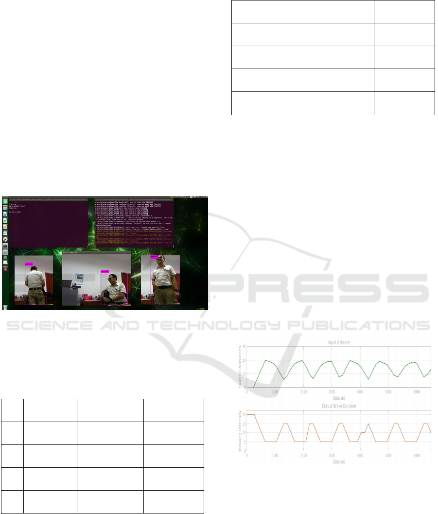
Furthermore, after the classification of objects,
the result of is shown by presenting a frame box
surrounding of the object with the note of the
classified object. The image of Figure 3.2 depicts
the stage of object categorization. For this study
purposes, the objective is concentrated only for a
human. Therefore, a person as an object is observed
for the categorization. The accuracy is the target.
Higher accuracy (in percentage) means that the
object is assured. Thus, it can be prioritized to
enable the deceleration.
The vehicle deceleration depends on the distance
of an object with respect to the camera. Longer the
distance will not activate the braking signal,
meanwhile closer means slowing the vehicle.
Figure 3.2. Monitor display during detection
The detection of the object requires a period. The
duration for object grouping process needs more
than 97% as seen on Tabel 3.1.
Table 3.1. Object detection data
No Object
Accuracy
(%)
Duration
(ms)
1
Person
pose 1
97 320
2
Person
pose 2
96 310
3
Person
pose 3
99 330
4
Person
pose 4
98 325
Moreover, the distance is also presented in the
table 3.2. This table compares the distance between
the actual and the camera measurement
Table 3.2. Distance measurement of an object
No Object
Distance
reference(m)
Distance
detected(m)
1 Person
pose 1
2.50 2.45
2 Person
pose 2
2.10 2.05
3 Person
pose 3
1.80 1.86
4 Person
pose 4
2.20 2.17
The result shows that the difference between the
predicted and real value is close. It is calculated that
the maximum error of the measurement is around
3%. This indicates that the system is suitable for the
application in a vehicle particularly with the slow
speed. It is also fit for heavy equipment vehicles
such as the fork lifts or loaders.
The decision signal is then sent to the braking
system by the value of intensity. Higher value
represents the higher deceleration meanwhile the
lower value denotes the lower intensity of slowing
down.
Further test is carried out using object movement
back and forth to test the braking decision. The
object particularly a person movement is saved into
a dataset. This data set is then processed into the
Matlab software to generate the function of braking
decision as shown in the Figure 3.3.
Figure 3.3. Object distance with braking decision
The x-coordinate represents the data taken. The
green curve at the top is the input (person
movement) represented in a distance (m) with
respect to the camera. The lower red curve represent
the braking intensity resulted from the input. It is
represented in a maximum intensity in a value of 20
when a human is closer than 5 m. Thus, hard stop is
denoted by 20. Meanwhile lowest value 0 means no
braking action.
ASAIS 2019 - Annual Southeast Asian International Seminar
40

4 CONCLUSIONS
The summary of the study are:
The detection of an object requires period of
around 300 ms with more than 90% accuracy.
The measurement of an object using 3D
camera has an error with the number of
maximum of 3%.
Braking action is taken by giving value as the
intensity shows that the electric signal is
higher when object distance is closer than 5
m.
ACKNOWLEDGEMENTS
The writers would like to thanks the Penelitian
Unggulan Program Studi (PUPS) Program for
financing the research work.
REFERENCES
Bellomo, N., Marcuzzi, E., Baglivo, L., Pertile, M.,
Bertolazzi, E., & De Cecco, M. (2009). Pallet Pose
Estimation with LIDAR and Vision for Autonomous
Forklifts. IFAC Proceedings Volumes, 42(4), 612-617.
doi: https://doi.org/10.3182/20090603-3-RU-
2001.0540
Boldt, J. L., Williams, K., Rooper, C. N., Towler, R. H., &
Gauthier, S. (2018). Development of stereo camera
methodologies to improve pelagic fish biomass
estimates and inform ecosystem management in
marine waters. Fisheries Research, 198, 66-77. doi:
https://doi.org/10.1016/j.fishres.2017.10.013
California. (2018). Forklift Accident Statistics. safety
numbers in ca.
Chi, Y., Yu, L., & Pan, B. (2018). Low-cost, portable,
robust and high-resolution single-camera stereo-DIC
system and its application in high-temperature
deformation measurements. Optics and Lasers in
Engineering, 104, 141-148. doi:
https://doi.org/10.1016/j.optlaseng.2017.09.020
Fleming, J. M., Allison, C. K., Yan, X., Lot, R., &
Stanton, N. A. (2019). Adaptive driver modelling in
ADAS to improve user acceptance: A study using
naturalistic data. Safety Science, 119, 76-83. doi:
https://doi.org/10.1016/j.ssci.2018.08.023
García, F., Prioletti, A., Cerri, P., & Broggi, A. (2018).
PHD filter for vehicle tracking based on a monocular
camera. Expert Systems with Applications, 91, 472-
479. doi: https://doi.org/10.1016/j.eswa.2017.09.018
Hu, Z., Lamosa, F., & Uchimura, K. (2005). A Compete
U-V-Disparity Study for Stereovision Based 3D
Driving Environment Analysis. Paper presented at the
The fifth International Conference on 3-D Digital
Imaging and Modeling.
Huang, N., He, J., Zhu, N., Xuan, X., Liu, G., & Chang, C.
(2018). Identification of the source camera of images
based on convolutional neural network. Digital
Investigation, 26, 72-80. doi:
https://doi.org/10.1016/j.diin.2018.08.001
Industries, C. (2019). 6 Common Forklift Accidents and
How to Prevent Them Retrieved Aug 19, 2019
Irawan, A., Yaacob, M. A., Azman, F. A., Daud, M. R.,
Razali, A. R., & Ali, S. N. S. (2018, 27-28 Aug.
2018). Vision-based Alignment Control for Mini
Forklift System in Confine Area Operation. Paper
presented at the 2018 International Symposium on
Agent, Multi-Agent Systems and Robotics (ISAMSR).
Jalali, A., Mallipeddi, R., & Lee, M. (2017). Sensitive
deep convolutional neural network for face recognition
at large standoffs with small dataset. Expert Systems
with Applications, 87, 304-315. doi:
https://doi.org/10.1016/j.eswa.2017.06.025
Murmu, N., Chakraborty, B., & Nandi, D. (2019). Relative
velocity measurement using low cost single camera-
based stereo vision system. Measurement, 141, 1-11.
doi:
https://doi.org/10.1016/j.measurement.2019.04.006
Nguyen, B., & Brilakis, I. (2018). Real-time validation of
vision-based over-height vehicle detection system.
Advanced Engineering Informatics, 38, 67-80. doi:
https://doi.org/10.1016/j.aei.2018.06.002
Oh, J., Kuenze, C., Jacopetti, M., Signorile, J. F., &
Eltoukhy, M. (2018). Validity of the Microsoft
Kinect™ in assessing spatiotemporal and lower
extremity kinematics during stair ascent and descent in
healthy young individuals. Medical Engineering &
Physics, 60, 70-76. doi:
https://doi.org/10.1016/j.medengphy.2018.07.011
Seelinger, M., & Yoder, J.-D. (2006). Automatic visual
guidance of a forklift engaging a pallet. Robotics and
Autonomous Systems, 54(12), 1026-1038. doi:
https://doi.org/10.1016/j.robot.2005.10.009
Williams, K., Rooper, C. N., De Robertis, A., Levine, M.,
& Towler, R. (2018). A method for computing
volumetric fish density using stereo cameras. Journal
of Experimental Marine Biology and Ecology, 508,
21-26. doi:
https://doi.org/10.1016/j.jembe.2018.08.001
Xu, M., Zhai, Y., Guo, Y., Lv, P., Li, Y., Wang, M., &
Zhou, B. (2019). Personalized training through Kinect-
based games for physical education. Journal of Visual
Communication and Image Representation, 62, 394-
401. doi: https://doi.org/10.1016/j.jvcir.2019.05.007
A Vehicle Braking System based on 3D Camera
41
