
Simulation of Wind Turbines with Variation of Number of Blades
and Blades Angle on Turbine Performance
Achmat Hidayat, Andi Idhil Ismail
Institut Teknologi Kalimantan
Keywords: Cross-flow, Power Coefficient, Tip Speed Ratio, Torque Coefficient, Wind Turbine, Turbine Performance.
Abstract: Crossflow wind turbines are known because of the advantages of producing maximum torque in a low tip
speed ratio also as a self-starting wind turbine. Therefore, it is an ideal wind turbine type for application as a
power generator in rural areas that have low wind speed between 2-5 m/s. The design parameter of cross-
flow wind turbines is required in order to improve turbine performance. This work investigates the influence
of blades number and blades angle on the performance of cross-flow wind turbines. Furthermore, to
investigate the effect of blades number and blades angle on crossflow wind turbine performance. Crossflow
wind turbines designed using 18 and 20 blades on 45˚, 60˚, and 75˚ blades angle on 0.68 aspect ratio
diameter. Based on the results obtained, cross-flow wind turbines with 18 number of blades and 45˚ blades
angle showed the best result.
1 INTRODUCTION
Crossflow type wind turbines are ideal turbines for
remote areas because crossflow type turbines can
produce large torque when a small tip speed ratio.
Crossflow wind turbines can effectively capture
wind when the wind conditions are in poor
condition.
If considering the limits of the type of classic
wind turbines, crossflow type wind turbines should
be a solution for areas that have poor wind
conditions and low speeds of 2-5 m / s [1].
At present, there is a lot of follow-up research on
crossflow type wind turbines. The efficiency
produced by crossflow wind turbines is high because
energy is produced from two sides of the turbine;
first, when the wind enters and pushes the front
turbine, the two come out of the turbine and push
back the backside of the wind turbine [2].
The purpose of the study was to measure the
performance of a crossflow type wind turbine with
variations in the number of blades and blade angle.
So that it can be seen the turbine design with the best
performing variation of research.
Turbine performance analysis is done with
Computational Fluid Dynamics (CFD). The design
made is 1 x 1 m2 outer diameter and 0.68 x 0.68 m2
in diameter with a ratio of aspect ratios of 0.68 with
two variations in the number of blades as much as
18 blades and 20 blades and also three variations of
blade angle 45 sudut, 60˚, and 75˚. Based on the
results of the study, the design of a crossflow type
wind turbine with 18 blades and a slope angle of 45˚
produced the highest Cp value of 0.45.
2 LITERATURE REVIEW
Computational Fluid Dynamics (CFD) is used to
help calculate the output value, CFD uses the
continuity equation as follows:
⍴/ ⍴/ (1)
Taking into account the conditions are ideal
conditions, the incompressible Navier-Stokes
calculation formula is used as follows:
⍴/ . Τ f. (2)
Kinetic energy is transferred to the rotor, and the
wind leaves the turbine. The actual power of the
turbine is efficiency or known as Cp. Thus, the Cp
value can be searched by comparing the actual
power and wind power available by:
Hidayat, A. and Ismail, A.
Simulation of Wind Turbines with Variation of Number of Blades and Blades Angle on Turbine Performance.
DOI: 10.5220/0009423101150118
In Proceedings of the 1st International Conference on Industrial Technology (ICONIT 2019), pages 115-118
ISBN: 978-989-758-434-3
Copyright
c
2020 by SCITEPRESS – Science and Technology Publications, Lda. All rights reserved
115
Cp=
⍴
(1)
Where Pt is the turbine output power, the Cp
value can depend on the type of blade, a number of
blades, blade settings, and others.
Ct=
⍴
(2)
Where Tt is motor torque. Tip Speed Ratio
(TSR) can be defined between turbine speed and
wind speed.
=
(3)
The maximum Tip Speed Ratio (TSR) value is
directly proportional to the value of turbine
efficiency [1].
3 METHODOLOGY
In this study, cross-flow wind turbines were carried
out using the 2D method. Cross-flow wind turbines
with D1 = 1 m and D2 = 0.68 m are placed in
modeling with a length of 15 m with a width of 7.5
m, and the distance between inlets to wind turbines
is 2.5 m. The domain of modeling can be seen in
Figure 1.
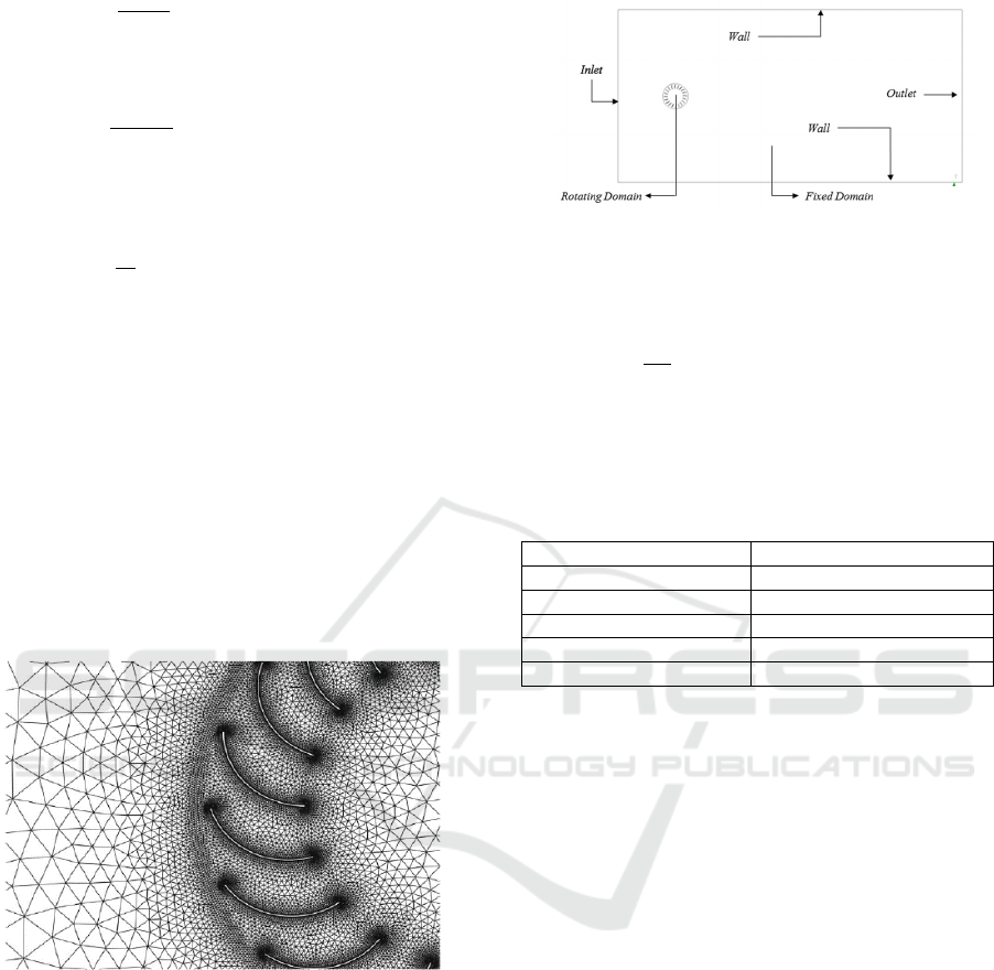
Figure 1 Meshing Quality
The computational domain is divided into two
subdomains, namely fixed domain and rotating
domain. The inlet is where the wind enters and is
modeled with a wind speed of 2 m / s. Meanwhile,
the right side is modeled as a pressure outlet with a
relatively static pressure of 0 Pa. The upper and
lower sides of the turbine are boundary walls as the
upper and lower limits of the wind turbine.
Figure 2 Computational Domain
Value Tip Speed Ratio (TSR) for the simulation
in Computational Fluid Dynamics (CFD) can be
defined by the equation as follows:
4
Where is the angular speed of the cross-flow
wind turbine and R = D1 / 2, which is the outer
diameter, and v is the air velocity modeled in the
simulation.
Table 1 Tip Speed Ratio (TSR)
(rad/s)
0 0
0.1 0.4
0.2 0.8
0.3 1.2
0.4 1.6
The meshing used is the Triangular Meshing
model used in all parts of the cross-flow wind
turbine domain. The quality of the meshing results in
the study shows that 0.78, where the meshing results
belong to the category of good meshing, which
makes meshing can be used to continue the research
(Wikantyoso, 2017). The following are the results of
meshing.
Meshing results will affect the accuracy of the
research conducted. Therefore, triangle meshing is
used because it has a sufficient level of accuracy.
4 RESULTS
The turbulence modeling k- is widely used to carry
out crossflow type wind turbine simulations because
the application is complex and is very suitable for
rotation so that the resulting results can approach the
results of experimental studies.
ICONIT 2019 - International Conference on Industrial Technology
116
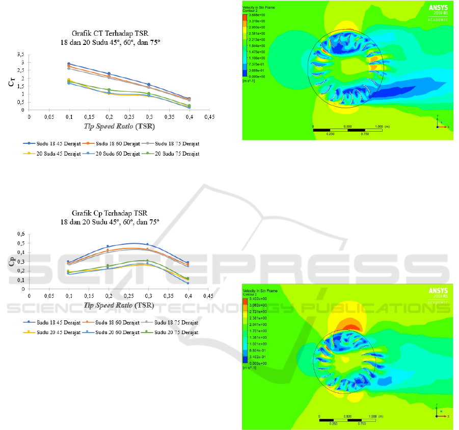
It can be seen that the trend of the torque
coefficient value (ct) decreases as the value of the
Tip Speed Ratio (TSR) increases because this value
of Ct is not directly proportional to the TSR value.
The highest Ct value is found when the TSR is 0.1,
and the lowest TSR value is at TSR 0.4
Figure 4 Grafik Cp
The highest Cp value is found in blade 18 with a
blade angle of 45˚ on TSR 0.3. This proves that
there are differences in performance with blades 18
and blade 20. Power Coefficient (Cp) generated
from wind turbines is directly proportional to the
actual power value produced by the turbine. Cp
value forms a parabolic pattern where when the
value reaches the maximum value, the value of Cp
will decrease after reaching the maximum point.
This is caused by when the value of Cp reaching the
maximum value will decrease directly proportional
to the value of TSR.
Based on Albert Betz's theory that the maximum
CP value that can be owned by a crossflow type
wind turbine is 0.59 because the air that hits the
turbine will pass the distance between one turbine to
another. Inner vortex increases at TSR 0.4 and TSR
0.5, causing a decrease in crossflow wind turbine
performance. Where the higher TSR values given to
variations will affect the performance of crossflow
type wind turbines. The performance of the wind
turbine reaches a peak at the point of TSR 0.2 and
TSR 0.3, which has a maximum CP value of 0.45.
Figure 5 Contour Velocity 18 Blades 45˚ Blades Angle
The velocity contour of blade 18 and 45 blade
angles show that there is an inner vortex that occurs
around the turbine blades. Inner vortex is backflow
from the wind that passes through the turbine so that
it disturbs the flow of air that passes through the
turbine blade. Inner vortex has an effect on the Cp
value generated by the turbine, the more there is an
inner vortex, the more resistance to airflow in the
turbine so that the turbine does not function
optimally.
Figure 6 Velocity Contour 20 blades
If we compare inner vortex in the number of
blades 18 and the number of blades 20, it can be
seen that the number of blades 20 has inner vortex
which is more because the number of blades 20 has
too many blades in the crossflow wind turbine
resulting in broken wind through the blade which
causes a lot of inner vortex occurred in the crossflow
wind turbine caused the flow of the wind can’t reach
its optimum level, so based on figure 5 the value of
Cp blade 20 is not optimal compared to the value of
Cp blade 18.
Figure 3 CT
Simulation of Wind Turbines with Variation of Number of Blades and Blades Angle on Turbine Performance
117
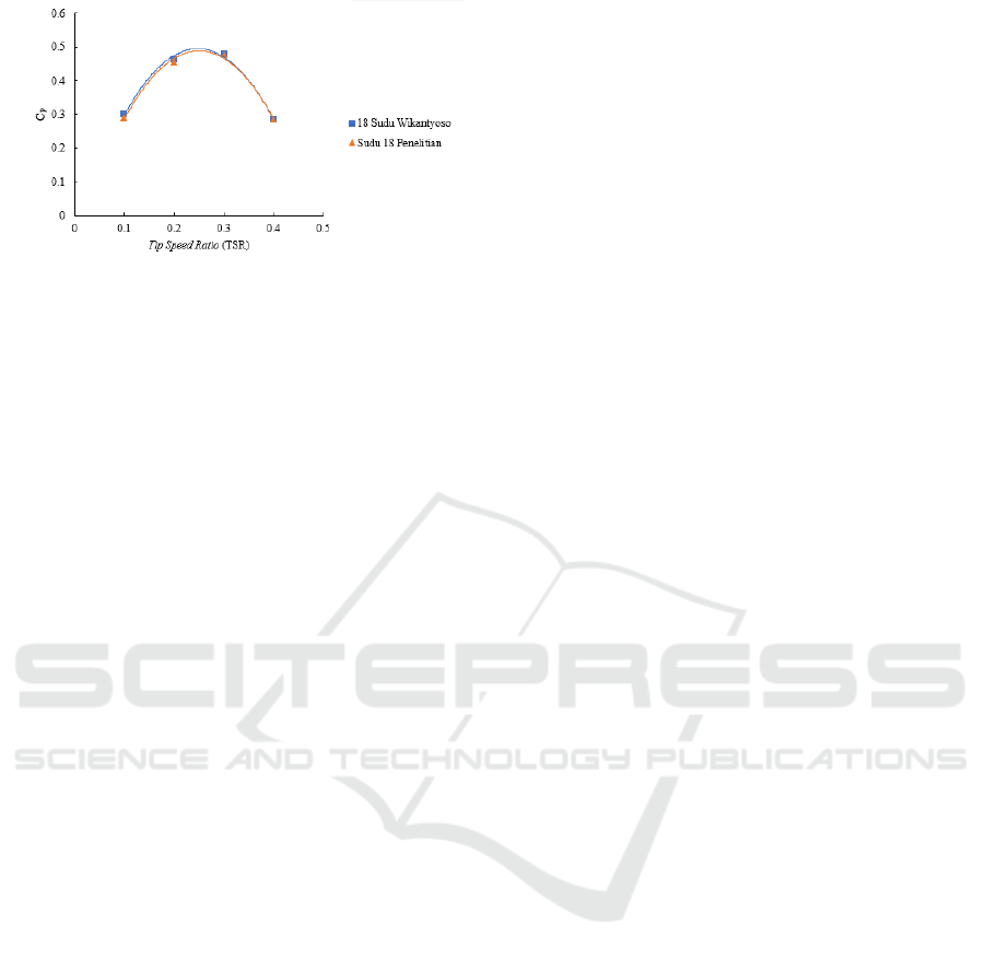
Figure 7 Results Comparation
The highest CP performance occurs at a TSR
blade 0.3. The highest CP value is due to the
variation of blade thickness of 10 mm, which has an
influence on the CP research results. The thickness
of the blade of 10 mm influences the speed of the
incoming winds, which hit the first level wind
turbine so that the speed of the incoming wind and
the speed of the outgoing wind. Blades can affect the
incoming wind, in research conducted the number of
recommended blades for wind turbines is blade 18 to
blade 22 if it exceeds the wind will split and cannot
enter the maximum
Based on figure 7, the value of the power
coefficient will increase maximally at Tip Speed
Ratio (TSR) 0.3 and decrease at TSR 0.4. This is
caused after the turbine reaches a maximum point at
TSR 0.3 after which the turbine will decrease after
reaching the maximum point. The maximum point
of a crossflow wind turbine is at a low Tip Speed
Ratio (TSR) of 0.3, and this makes a crossflow wind
turbine an excellent turbine for low wind speeds. If
using a TSR value of 0.5 to TSR of 0.6, the results
of the performance of a cross-flow wind turbine will
experience a decrease so that the value of the power
coefficient can experience a minus. The comparison
of CP values can reach 0.5 very high when
compared with the Beltz momentum theory.
5 CONCLUSIONS
Based on the results of the analysis after conducting
research, it is suggested that the turbine can only
operate with a maximum Tip Speed Ratio (TSR) at
0.4, the higher the TSR value, the maximum turbine
drop will occur after reaching the maximum value
on TSR 0.3. And a comparison with experimental
research is needed to ensure the simulation results
with experimental research in the real world.
Furthermore, based on the results of the contour
speed analysis it is recommended to use symmetrical
casing to make the wind direction more regular and
can change the direction of the wind so that it can
make the wind direction more convergent which
causes a little backflow which makes the Cp value of
the turbine more leverage. For 1 x 1 m turbine size,
it is recommended to use blade 18 because, based on
the results of the study, it produces a value that is
more optimal when compared to blade 20.
REFERENCES
Al Maaitah, A., 1993. The design of the Banki wind
turbine and its testing in real wind conditions.
Pergamon Press Ltd, Volume 3, p. 1.
Dragomirescu, A., 2010. Performance assessment of a
small wind turbine with crossflow runner by numerical
simulations. Elsevier Ltd, pp. 2-9.
Hau, E., 2005. Wind Turbines: Fundamentals,
Technologies, Application,. 2nd penyunt. s.l.:Springer.
Jain, P., 2011. Wind Energy Engineering. United States:
McGraww-Hill.
Kurniawati, D. M., 2018. Eksperimen Pengaruh Aspek
Rasio Diameter Terhadap Tinggi dan Jumlah Sudu
Terhadap Performa Turbin Angin Cross flow. AIP
Publishing, pp. 1-6.
Mathew, S., 2006. Wind Energy Fundamentals, Resource
Analysis, and Economics. Malapuram: Springer.
Natayuda, G., 2017. Analisa Termodinamika dan Kinerja
Turbin Angin Tipe Sumbu Horizontal Menggunakan
Computational Fluid Dynamics. Universitas Jenderal
Achmad Yani.
Permadi, M. F. W. & Siregar, I. H., 2018. Uji
Eksperimental Turbin Angin Sumbu Vertikal Jenis
Crossflow Dengan Variasi Jumlah Sudu.
JTM.unesa.ac.id, Volume 06, pp. 15-31.
Shigemitsu, T., 2016. Performance and Flow Condition of
Cross-Flow Wind Turbine with a Symmetrical Casing
Having Side Boards. International Journal of Fluid
Machinery and Systems, Volume IX, p. 171.
Wikantyoso, M. F., 2017. Studi Pengaruh Ketebalan dan
Jumlah Sudu. digilib.uns.ac.id, pp. 45-46.
ICONIT 2019 - International Conference on Industrial Technology
118
