
Chip Formation and Shear Plane Angle Analysis on Carbon Steel
Drilling using Solid Carbide Tools
Rieza Zulrian Aldio
Department of Mechanical Engineering, Universitas Islam Riau, Pekanbaru, Indonesia
Keywords:
Carbide Drill Bit, Chip Formation, Drilling, Shear Plane Angle
Abstract:
The analysis of the chip formation and shear plane angle from the drilling process are conducted as a mean to
determine the best drill bit used. Both aspects that influenced by the drill bit will define the machinability and
quality of the machining process. The aim of this experiment is to determine which is the best drill bit to use.
There are nine types of drill bit used in this experiment. All of the drills used are made of the solid carbide.
The chips are obtained from the drilling conducted by HPMT Industries Sdn Bhd. There are several types of
chips from the experiment, such as continuous, discontinuous and segmented chip. It is found that the chip’s
thickness and the helix angle of the drill bit affect the value of the shear plane angle created. Since all drill
bits are made of the same material, the helix angle of the drill bit become the main factor of choosing the best
drill bit because of the relationship between it influenced the shear plane angle value.
1 INTRODUCTION
One of the workpiece that is frequently and generally
used in the machining process is steel. There are sev-
eral types of steel used in the machining process such
as stainless steel, carbon steel and others. Each type
of steel has a different nature. Stainless steel is the
most common type of steel used in the manufactur-
ing industry. For example, corrosion resistant prop-
erties of stainless steel is due to a chromium content
of 10-12 percent of the total weight of stainless steel
(Kalpakjian and Schmid, 2006). Then there is also
carbon steel which is also often used in industry be-
cause of its low cost and ease of manufacture (Smith
and Hashemi, 2006).
One of the type of machining process which is of-
ten used for steel is drilling process. Drilling pro-
cess is the process by which drill bit will result in a
hole in the workpiece through direct contact between
the tool and the workpiece surface. Drilling process
is one of the most important machining processes in
the automotive and aircraft industries. (El-Sonbaty
et al., 2004) states that the industries required more
than 100,000 holes for small aircraft engines, mostly
used as a fastener. There are several forms of chips
that could resulted from the drilling process (Shar-
man et al., 2008). For example, the long continuous
chips are bad shape because chips will stick to the
surface of the tool and affect the performance of the
tool while performing the drilling process (Feng et al.,
2005). Long chips also make the chip evacuation be-
come more difficult and cause the drill to require more
power, which would increase the risk of broken drill
(Batzer et al., 1998). For this reason, the form and
evacuation process of the chips have important roles.
Chips will have direct contact with the flutes on
the twist drill during the drilling process. The geome-
try of the tool used will have an impact on the process
of moving chips (Abrao et al., 2008). Because of that,
the shape that commonly found has curls form, which
is according to the flute’s shape. (Bakkal et al., 2005)
in experiments on the chip’s morphology of drilling
metal glass found that there are six forms of chips
such as powder, short ribbon, long ribbon, long spi-
ral, long twisted ribbon and fan shape.
Movement of the chips on the flutes will cause
bending moments which can lead to chip fracture.
(Sakaurai et al., 1998) states that the chip will be
broken when the friction torque between the hole
wall and chip’s surface is beyond the chip’s torque.
The size of the chip will have impact on the sur-
face roughness, which will produce rougher surface
(Batzer et al., 1998). The performance of a tool can
be determined by the shape of the resulting chips.
Therefore, apart from the chip removal process,
the shape and length of chips resulted from the
drilling process should be reviewed in order to accom-
plish better performance of the drilling process. In
Zulrian Aldio, R.
Chip Formation and Shear Plane Angle Analysis on Carbon Steel Drilling using Solid Carbide Tools.
DOI: 10.5220/0009406203370341
In Proceedings of the Second International Conference on Science, Engineering and Technology (ICoSET 2019), pages 337-341
ISBN: 978-989-758-463-3
Copyright
c
2020 by SCITEPRESS – Science and Technology Publications, Lda. All rights reserved
337
addition to differences in material and machining pa-
rameters on the tool used, the difference in the shape
or geometry of the tool will affect the shape of the re-
sulted chips (Wan and Tang, 2011). Geometric dif-
ferences such as rake angle or helix angle and the
point angle will affect the shape, size and length of
the chips. Point angle, helix angle and size of flutes
on the tool will affect the movement of chips (Feng
et al., 2005).
So in this experiment will be analyzed on the frag-
ments resulting from each type of device used. Each
tool has a different geometry and analysis on the re-
lationship between the different tool geometry and
shape of the pieces will also be done. Then the re-
lationship between the rake angle of the tool with the
resulting shear plane angle will also be reviewed.
Figure 1 shows the geometry of the typical drill
bit used in machining.
Figure 1: Drill Bit Geometry
2 EQUIPMENT
The workpiece used is carbon steel S45C. CNC ma-
chine is used for the drilling process. The diameter of
all cutting tool used is 8 mm. All of them are not us-
ing coolant. There 9 drill bits, each has different helix
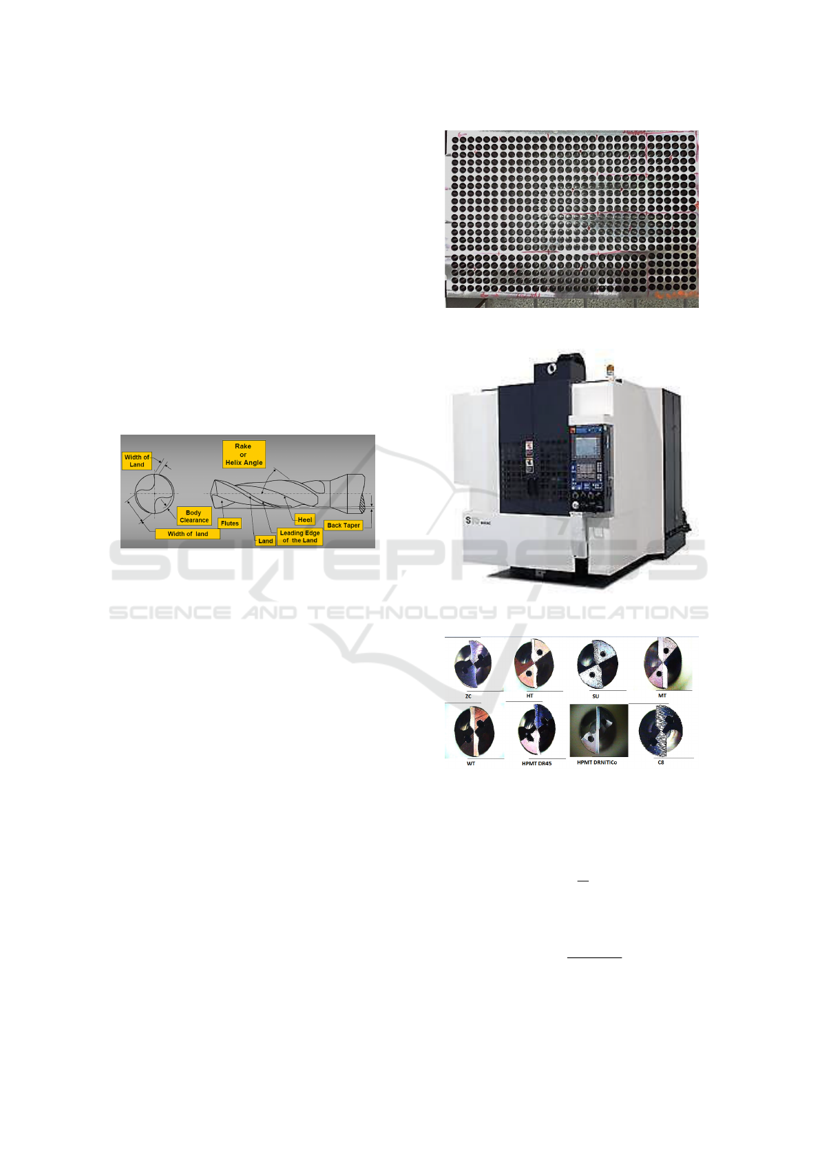
angle value. Figure 2 shows the holes produced from
the drilling process. From the process, there are 600
holes produced by using each cutting tools. Then fig-
ure 3 show the CNC Drilling Machine Makino S-33
that used in the drilling process.
3 METHODOLOGY
Every drill bit will drill 600 holes with same machin-
ing parameters, shown in table 1. Then the chips
are taken randomly between the drilling process.
the chip’s thickness measured using vernier calliper.
Thus, using the thickness ratio and helix angle value,
the shear plane angle value can be found. These
formulas are used for the calculation.
Figure 2: Carbon Steel S45C
Figure 3: Makino S-33 CNC Machine
Figure 4: Drill Bits Used In The Drilling Process
r =
to
tr
(1)
tanΦ =
r cos α
1 − r sinα
(2)
ICoSET 2019 - The Second International Conference on Science, Engineering and Technology
338
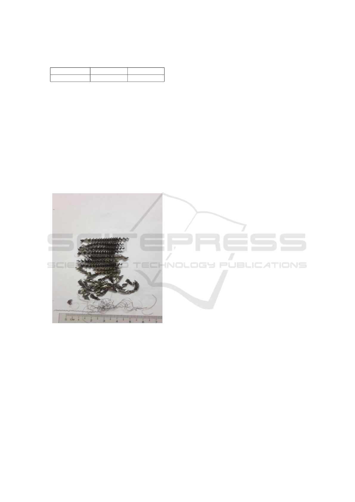
Table 1: Machining Parameters Used
Cutting speed Feed rate Depth of cut
140 m/min 0.16 mm/rev 42 mm
4 RESULTS AND DISCUSSION
4.1 Chip Formation
From the chips sample, there are several forms of chip
resulted from each type of cutting tools. Long heli-
cal continuous chip is always resulted in the drilling
process. There are also discontinuous and segmented
chip resulted. But there are only two cutting tools re-
sulting segmented chips. Beside the shape, the length
and thickness of the chips are also measured. The
length of the chips are between 3 to 6 cm. Figure 5
below shows the sample of the chips.
Figure 5: Type of Chips Resulted From The Drilling Pro-
cess
There are several types shapes of the chips re-
sulted. With continuous being the dominant one,
while some discontinuous and segmented are also re-
covered. There are no real significant difference in the
shape due to the similarity value of the rake angle.
For the thickness value however, the differences
between all the chips resulted from each cutting tools
are quite similar. This is due to the similarity of the
feed rate used in the drilling process. Table 2 show the
value from the maximum length and thickness mea-
surement of the resulted chips.
Chips from cutting tool C8 has the least maximum
length of all the chips. As for he longest is from
the cutting tool WT. Cutting tool ZC produce longest
chips at 4.5 mm, and this cutting tool is the cutting
tool that produce the most many long continuous he-
lical chips. Long continuous chips also resulted from
the use of all the cutting tools. But only ZC produce it
as the most dominant chip’s form. For the segmented
chips, there are two cutting tools produced it, they are
HT and MT. Using MT, there is also produced long
continous string chips. As for the cause of this oc-
curence, is likely due to the high cutting speed and
influenced by the wear condition of the cutting tools.
From table 2, it can also show the value of the chip
thickness. The small difference might happened due
to the similar use of machining parameter,, especially
feed rate that affect the chip thickness. There is no
change in the parameter, which is making unclear to
compare the chip thickness resulted from each cutting
tools. Thus, the similarities between the values are
obtained.
4.2 Surface Integrity of the Chip
Observation of the surface of the resulting chips were
also conducted. The both of the chip surface was ob-
served using an optical microscope. Of all the pieces,
it is found that many chips with good machined sur-
face (outside) or good quality. However, there is also
the outer surface of chips having a surface shape is
not good, as there is friction and cracked. The condi-
tion of the chip surface in contact with the workpiece
has a resemblance to each other. There are traces of
the strain acting on the surface of the chip, which oc-
curred during the drilling process. The traces are re-
sulted by the cutting tools.
From observation, it can be seen that the shape
of the surface of the chips of each tool has a shape
similar or even identical. Due to the dominant circu-
lar chip, it is difficult to observe the inner part of the
chip. To do the observation of this part, the discontin-
uous chip type is observed so the inner surface can be
observed. From the figure below, it is shown that the
chips surface from HPMT DRNiTiCo has poor condi-
tion than the others. It can occured due to the cutting
tools became dull (due to the wear).
4.3 Shear Plane Angle Analysis
Feed rate is used as the replacement for the t
o
.There
is a relationship between shear plane angle and rake
angle. Because rake angle will define the sharpness
of the cutting tool. Rake angle will affect the shear
plane angle resulted. For drilling process, the rake
angle is replace by the helix angle. Because helix an-
gle (on flute) is the part that directy cut or touch with
Chip Formation and Shear Plane Angle Analysis on Carbon Steel Drilling using Solid Carbide Tools
339
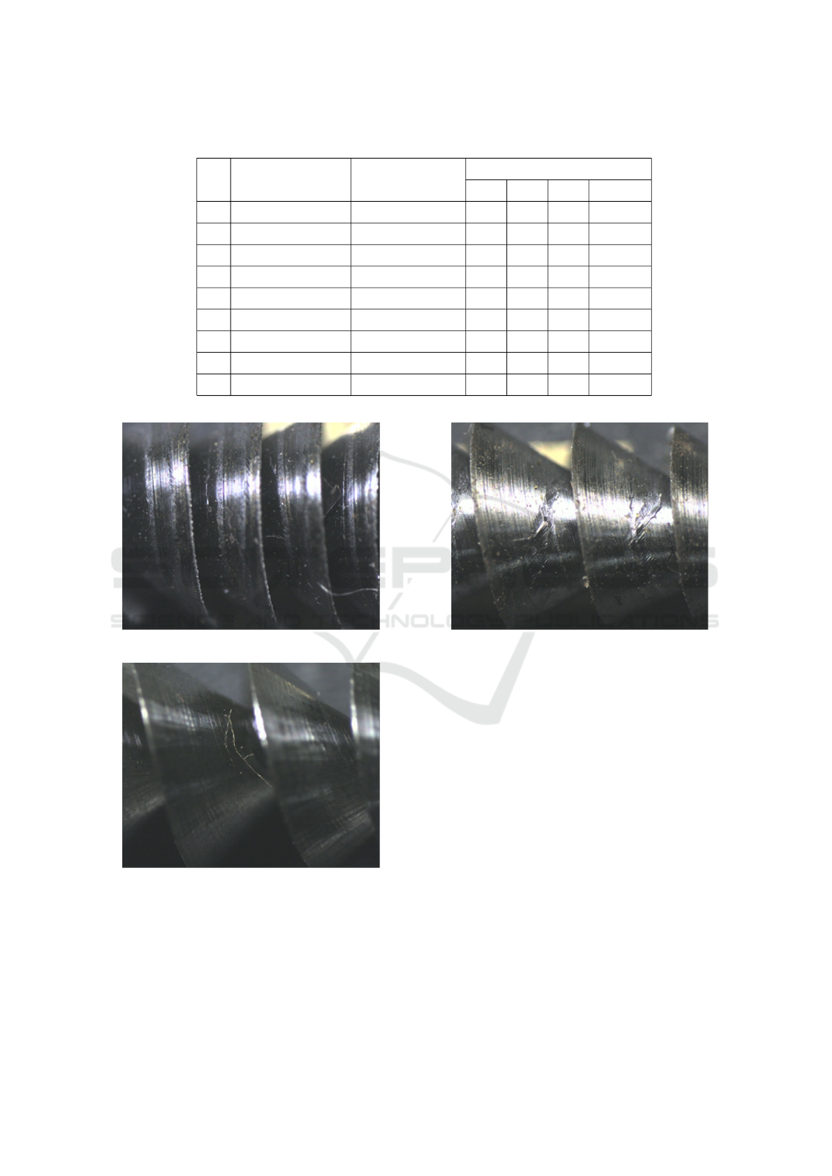
Table 2: Chip’s Length And Thickness Measurement
No Drill Bit Max Length (cm)
Thickness (mm)
1 2 3 Average
1 ZC 4.5 0.23 0.25 0.25 0.24
2 HT 4 0.29 0.24 0.23 0.25
3 SU 4.2 0.21 0.24 0.25 0.23
4 MT 4.4 0.26 0.2 0.21 0.22
5 WT 6 0.27 0.31 0.29 0.29
6 HPMT DR45 3.8 0.24 0.26 0.23 0.24
7 HPMT DRNiTiCo 3.5 0.31 0.29 0.25 0.28
8 C4 4.5 0.24 0.27 0.26 0.26
9 C8 3 0.21 0.22 0.25 0.23
Figure 6: Chips of Drill Bit C8
Figure 7: Chips of MT
the workpiece’s surface and resulting the chip. The
chip also flow through this part. So in this case, helix
angle is related to the shear plane angle.Table 3 shows
the rake angle and shear plane value.
From the table 3, it is known that the least thick-
ness will cause the shear plane angle to increase. That
Figure 8: Chips of HPMT DRNiTiCo
shows the relationship between thickness and shear
plane angle. Beside that, rake angle also influence the
shear plane angle. It is seen that the smaller rake an-
gle tend to produce smaller shear plane angle, except
for C4 and C8. The value of the shear angle also will
decreased if the rake angle is too large, such as WT
show. This means that the rake angle value should be
optimized to get the optimum value of the shear plane
angle.
The chip thickness has more clear relationship
with the shear angle. The smaller thickness will re-
sulting the bigger shear plane angle. As figure 6,7 and
8 shows that the optimum value of the shear plane is
around rake angle with 30
◦
.
5 CONCLUSION
From the measurement and observation of the chip,
it is concluded that there are several type of chip
ICoSET 2019 - The Second International Conference on Science, Engineering and Technology
340
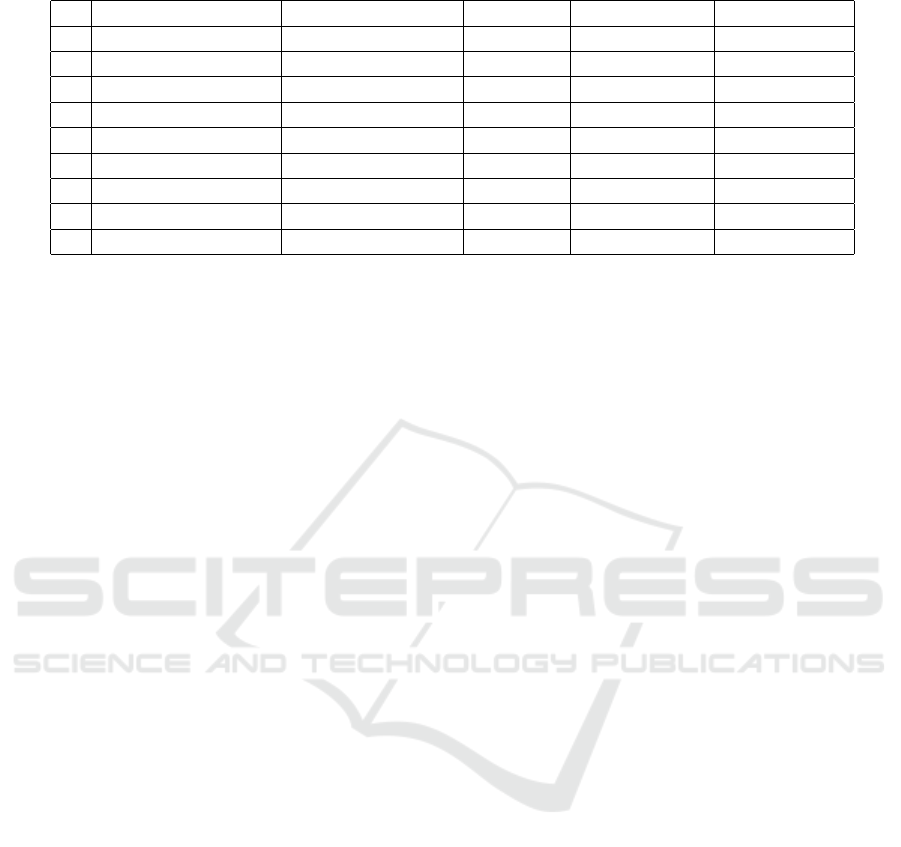
Table 3: Shear Plane Angle Value of Every Drill Bit
No Drill Type Chip Thickness (tc)(mm) Cutting Ratio Helix / Rake Angle Shear Plane Angle
1 ZCC 0.24 0.67 30.21 41.14
2 Hitachi (HT) 0.25 0.64 28.67 39.02
3 Sumitomo (SU) 0.23 0.7 30.16 43.03
4 Mitsubishi (MT) 0.22 0.73 30.69 45.02
5 Walter Titex (WT) 0.29 0.55 33.17 33.37
6 HPMT DR459670800 0.24 0.67 30.22 41.14
7 HPMT DRNiTiCoD08800 0.28 0.57 30.16 34.63
8 Coromant 460 (C4) 0.26 0.62 26.24 37.46
9 Coromant 860 (C8) 0.23 0.7 26.41 42.32
resulted such as continuous, discontinuous and seg-
mented chip. Continuous is the most dominant chip
of all, since it appeared on each tool. The segmented
only appeared on HT and MT, and could occured due
to the tool wear and randomness of the chip collected
from the drilling process.
Shear plane angle is calculated and shows that it
has strong and clear relationship with chip thickness
value. As for the rake angle, it shows that the opti-
mum value of rake angle must be specified if want
to increase the shear plane angle. Meaning also to
reduce the chip thickness to accomodate better chip
evacuation during drilling process.
ACKNOWLEDGEMENTS
The author would like to give an acknowledgment to
HPMT Industries Sdn. Bhd. members, especially
Research and Development Department for their co-
operation in data. The author also thanks Universiti
Kebangsaan Malaysia as the organisation that provide
their facilities for the research’s purpose.
REFERENCES
Abrao, A. M., Rubio, C., C., J., Faria, P. E., and Davim,
J. P. (2008). The effect of cutting tool geometry on
thrust force and delamination when drilling glass fibre
reinforced plastic composite. Materials and Design.
29:508 513.
Bakkal, M., Shih, A. J., McSpadden, S. B., Liu, C. T., and
Scattergood, R. O. (2005). Light emission, chip mor-
phology, and burr formation in drilling the bulk metal-
lic glass. International Journal of Machine Tools and
Manufacture 45 741 152.
Batzer, S. A., Haan, D. M., Rao, P. D., Olson, W. W., and
Sutherland, J. W. (1998). Chip morphology and hole
surface texture in the drilling of cast Aluminum alloys.
Journal of Materials Processing Technology 79.
El-Sonbaty, I., Khashaba, U. A., and Machaly, T. (2004).
Factors affecting the machinability of GFR/epoxy
composites. Compos Struct ;63(34):329 38.
Feng, K., Ni, J., and Stephenson, D. A. (2005). Continu-
ous chip formation in drilling. International Journal
of Machine Tools & Manufacture 45.
Kalpakjian, S. and Schmid, S. R. (2006). Manufacturing
Engineering and Technology. Upper Saddle River:
Pearson Prentice Hall.
Sakaurai, K., Adachi, K., and Hanasaki, S. (1998). Break-
ing mechanism of chips in inter- mittently decelerated
feed drilling of aluminum alloys. Japan Institute of
Light Metals 48 (4) 195 198.
Sharman, A. R. C., Amarasinghe, A., and Ridgway, K.
(2008). Tool life and surface integrity aspects when
drilling and hole making in Inconel 718. Journal of
materials processing technology. 200:424 432.
Smith and Hashemi (2006). Foundations of Materials Sci-
ence and Engineering.
Wan, Z. and Tang, Y. (2011). Characteristics of uncurled
and reversely curled chip during orthogonal cutting.
International Journal of Machine Tools and Manufac-
ture, 51(10-11):831–835.
Chip Formation and Shear Plane Angle Analysis on Carbon Steel Drilling using Solid Carbide Tools
341
