
Consideration of the Different Pile Length Due to Soil Stress and Inner
Forces of the Nailed-slab Pavement System under Concentric Load
Anas Puri
1
, Roza Mildawati
1
and Muhammad Solihin
2
1
Department of Civil Engineering, Universitas Islam Riau, Pekanbaru, Indonesia
2
Undergraduate Student Department of Civil Engineering, Universitas Islam Riau, Pekanbaru, Indonesia
Keywords:
Inner Forces, Lateral Deflection, Stress Distribution, Longer Piles, Soft Clay, Soil Stress.
Abstract:
Concentric loading on the Nailed-slab Pavement System causes stress in the soil and the inner forces in
structural elements. The load stress is transferred to the soil by the structural elements tends to concentrate in
the centerline area under the system. Since load stress is concentrated in the center line area, the soil stress and
inner forces can be higher in the center of the system. To reduce the soil stress and inner forces of structural
elements, the longer pile can be put in the center area of the system. This research is aimed to learn the
soil stress and inner forces behavior of the Nailed-slab Pavement System in case putting the longer pile in the
center area of the system. The maximum double wheel load was taken 50 kN which transfer to the slab surface
by contact pressure. Wheel load was loaded in the center of the slab. The Nailed-slab materials properties and
soft clay properties were taken from the previous researcher. The piles in the center area of the Nailed-slab
were longer 33.3% than others. Results show that the Nailed-slab by longer piles in the center area can reduce
the soil stress significantly for maximum shear stress up to 28%. The inner forces were also reduced by about
43% to 46% and caused the reducing in lateral deflection of pile tip about 37%. It can be concluded that the
increasing pile length in the central area of the system can reduce soil stress and inner forces of the system.
1 INTRODUCTION
The uniform pile length in bearing the vertical
loadings on the Nailed-slab Pavement System was
used by the previous researchers. Such as the research
by Hardiyatmo (2011), (Puri et al., 2011a; Puri et al.,
2011b; Puri et al., 2012; Puri et al., 2013; Puri et al.,
2014; Puri et al., 2015; Puri and Mildawati, 2019)
and (Puri et al., 2015; Puri, 2016) for Nailed-slab
System on the soft clay. The distribution of soil stress
will be experienced a maximum settlement due to the
load position. A maximum settlement on the center of
the Nailed-slab can be occurred due to the concentric
load. The soil stress and inner forces analysis can be
done by the finite element method of Plaxis software
(Puri et al., 2015; Puri, 2016; Puri and Mildawati,
2019; WARUWU, 2018). Inner forces analysis of
Nailed-slab can be also done by the finite element
method of SAP2000 (Puri et al., 2015; Somantri,
2013) and Abaqus (Syarif et al., 2018; Diana, 2017).
This research is aimed to investigate the effect of
different pile length due to the soil stress and inner
forces behavior of the Nailed-slab Pavement System.
2 METHODOLOGY
This research used the soil and Nailed-slab structural
data from Puri (2015). The soft soil geometry was
set with thickness 10 m. There was the dense
sand layer below the soft clay which neglected in
the analysis. The considered load 50 kN was a
concentric load on the pavement slab. The boundary
condition of the soil is shown in Figure 1. Figure 1a
shows the Model 1 which used uniform pile length
and Figure 1b for different pile length (piles in the
center area longer 33.3% the edge piles). (Somantri,
2013) analyzed full-scale Nailed-slab model by using
soil properties from experimental project. (Puri and
Mildawati, 2019) simulated the effect of dimensions
of Nailed-slab by using soil and structural properties
from full-scale test.
The dimension of Nailed-slab model was 6.0 m
x 3.6 m and 0.15 m slab thickness. The slab is
supported by 5 piles. Pile diameter was 0.30 m. Pile
spacing was 1.20 m. The pile-slab connections were
monolithically. The pile length for model 1 was 1.50
m and for model 2 was 1.50 m for edge piles and
2.00 m for piles in the center area of the slab. The
Puri, A., Mildawati, R. and Solihin, M.
Consideration of the Different Pile Length Due to Soil Stress and Inner Forces of the Nailed-slab Pavement System under Concentric Load.
DOI: 10.5220/0009364903110314
In Proceedings of the Second International Conference on Science, Engineering and Technology (ICoSET 2019), pages 311-314
ISBN: 978-989-758-463-3
Copyright
c
2020 by SCITEPRESS – Science and Technology Publications, Lda. All rights reser ved
311

Table 1: Model and parameters of soil.
Parameters Name/ Notation Soft clay Unit
Material model Model Mohr-Coulomb -
Material behavior Type Un-drained -
Saturated density γsat 16.30 kN/m
3
Dry density γd 10.90 kN/m
3
Young’s Modulus E 1,790.00 kPa
Poisson’s ratio ν 0.45 -
Un-drained cohesion cu 20.00 kPa
Internal friction angle φ 1.00 o
Dilatancy angle ψ 0.00 o
Initial void ratio e0 1.19 -
Interface strength ratio R 0.80
Table 2: Model and parameters of structural elements in
FEM 2D plain strain.
Parameters Name/Notation Lean concrete
Structural elements
Unit
Slab Pile
Material Model Model Volume element Plate Plate -
Material behavior Type Elastic Elastic Elastic -
Normal stiffness EA - 4,554,000 738,528 kN/m
Flexural rigidity EI - 8,539 5,649.74 kNm
2
/m
Equivalent thickness d - 0.15 0.3 m
Weight w - 3.60 0.9 kNm/m
Poisson’s ratio v 0.2 0.15 0.20 -
Unit weight γ 22 24 24 kN/m
3
Young’s modulus E 17,900 25,300 19,600 MN/m
2
Interface
strength ratio
R 0.80 0.80 0.80
models were analyzed by 2D finite element method
(FEM). In 2D FEM plain strain analysis, the soft
clay was modeled by Mohr-Coulomb in un-drained
condition. All structural elements were modeled
by plate element in linear-elastic behavior. Lean
concrete was modeled by soil with the linear-elastic
non-porous material. Soil parameters and idealization
of structural elements are presented in Table 1 and 2
respectively.
3 RESULTS AND DISCUSSIONS
Results are shown in Tabel 3, 4 and Figure 2.
The loaded Nailed-slab caused soil and structural
movements and stresses.
3.1 Soil Stress
Table 3 shows the results of the effects of different
pile length due to soil stresses. The soil effective shear
stresses are shown in Figure 2. The soil effective
shear stresses for Model 2 has a similar shape to
Model 1. Maximum shear stress, effective stress,
and maximum excess pore pressure tend to decrease
(Table 3). That was beneficial for the soil. While
the maximum excess pore water pressure under the
central pile tip tends to increase about 12%. The
distribution of the effective shear stress in the soil is
shown in Figure 2. Model 2 can significantly reduce
the maximum effective shear stress and maximum
excess pore water pressure 37% and 32% respectively.
While the maximum excess pore water pressure under
the central pile tip a little bit increase about 12% and
effective stress of soil insignificantly decrease. Model
2 also has a better stress distribution because it has
wider stress distribution.
Table 3: The stresses in the soil
Description Unit
Model
1
Model
2
Maximum shear stress,
τ
xy−max
kN/m
2
-15.31 -9.69
Effective stress, σ kN/m
2
65.33 64.27
Max. excess pore water
pressure, U
kN/m2 107,49 72,93
Max. excess pore water
pressure under the central
pile tip, U
kN/m2 -11.00 -12.31
3.2 Inner Forces of Structural
Table 4 shows the inner forces in the structural
elements. The slab has a negative bending moment in
the area of the slab center similar to other researchers
(Puri et al., 2015; Puri, 2016; Diana, 2017; Puri and
Mildawati, 2019). Using the longer pile in the center
area of the slab were result in the good effects. All
inner forces decreased by using the longer pile, except
for bending moment on the pile head was relatively
constant. Model 2 can significantly decrease the
bending moment of slab of about 46%. Otherwise,
it can also decrease the bending moment and axial
force of pile 46% and 43% respectively. Decreasing
the inner forces in the structural elements is very
beneficial for this system. In the case of lateral
deformation of pile head, Model 2 can significantly
reduce it about 37%.
Table 4: The extreme inner forces in the structural elements.
Description Unit
Model
1
Model
2
Bending moment of
slab, M
s
kNm/m -42.62 -22.78
Bending moment of
pile, M
p
kNm/m 2.94 2.95
The axial force of
pile, P
kN 12.33 6.61
The shear force of
pile, H
kN 15.33 8.72
Lateral deflection
of pile tip, U
x
mm -7.53 -4.73
ICoSET 2019 - The Second International Conference on Science, Engineering and Technology
312
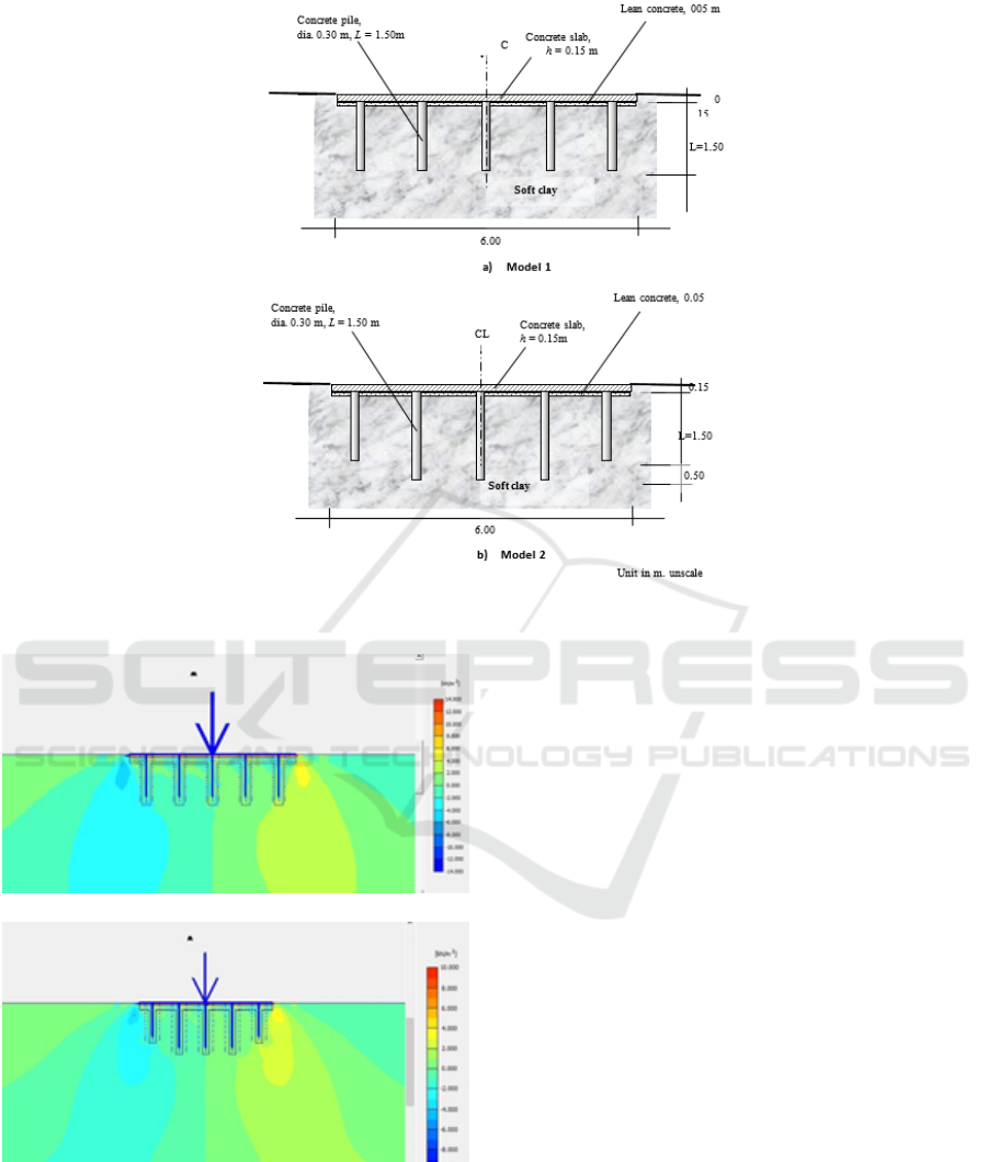
Figure 1: Variation of the model in the analysis.
Model 1, τ
xy−max
= 15.31 kN/m
2
Model 2, τ
xy−max
= 9.69 kN/m
2
Figure 2: Distribution of effective shear stress of soil.
4 CONCLUSIONS
The results of this study prove that although the
JCI change pattern follows the changing pattern
of macroeconomic variables, but after it has been
proven by a series of statistical tests, none of the
macroeconomic variables affect JCI in the short run.
This might be caused by investors in Indonesia pay
more attention to the fundamental factors which are
the company’s financial performance. In addition,
stock indices in a country do have a tendency to
increase due to developments in a country’s Stock
Exchange.
REFERENCES
Diana, W. (2017). Behavior of Nailed-slab System on
Peat Soil. Dissertation, Universitas Gadjah Mada,
Indonesia (in Indonesian).
Puri, A. (2016). Behavior of uplift resistance of single
pile row nailed-slab pavement system on soft clay
sub grade. In Proceeding of the 3rd Asia Future
Conference (AFC).
Puri, A., Hardiyatmo, C., Suhendro, B., and Rifa’i, A.
(2011a). Experimental study on deflection of slab
which reinforced by short friction piles in soft clay. In
Proc. of 14 th Annual Scientific Meeting (PIT) HATTI,
pages 10–11.
Puri, A., Hardiyatmo, H., Suhendro, B., and Rifa’i, A.
(2011b). Contribution of wall barrier to reduce the
deflection of nailed-slab system in soft clay. In Proc.
of 9th Indonesian Geotech. Conf. and 15th Annual
Consideration of the Different Pile Length Due to Soil Stress and Inner Forces of the Nailed-slab Pavement System under Concentric Load
313

Scientific Meeting (KOGEI IX & PIT XV) HATTI,
pages 299–306.
Puri, A., Hardiyatmo, H., Suhendro, B., and Rifa’i,
A. (2013). Application of method of nailed-slab
deflection analysis on full scale model and
comparison to loading test. In Proc. the 7 th National
Conference of Civil Engineering (KoNTekS7), pages
G201–G211.
Puri, A., Hardiyatmo, H. C., Suhendro, B., and Rifa’i,
A. (2012). Determining additional modulus of
subgrade reaction based on tolerable settlement for the
nailed-slab system resting on soft clay. International
Journal of Civil and Environmental Engineering
IJCEE-IJENS, 12(03):32–40.
Puri, A., Hardiyatmo, H. C., Suhendro, B., and Rifa’i, A.
(2014). Behavior of nailed-slab system on soft clay
due to repetitive loadings by conducting full scale
test. In Proc. 17thIntrntl. Symp. FSTPT, University
of Jember, pages 739–750.
Puri, A., Hardiyatmo, H. C., Suhendro, B., and Rifa’i, A.
(2015). Pull out test of single pile row nailed-slab
system on soft clay. In Proc. The 14th International
Conference on Quality in Research (QiR), Universitas
Indonesia, Lombok, pages 63–68.
Puri, A. and Mildawati, R. (2019). Investigasi numerik
perkerasan jalan sistem pelat terpaku terhadap variasi
dimensi struktur. BENTANG: Jurnal Teoritis dan
Terapan Bidang Rekayasa Sipil, 7(1):1–7.
Somantri, A. K. (2013). KAJIAN LENDUTAN SISTEM
PELAT TERPAKU PADA TANAH PASIR DENGAN
MENGGUNAKAN METODE BEAM on ELASTIC
FOUNDATIONS (BoEF) DAN METODE ELEMEN
HINGGA. PhD thesis, Universitas Gadjah Mada.
Syarif, F., Adi, A. D., and Saputra, A. (2018). Studi
karakteristik fondasi pelat tipis dengan pengaku tiang
“+” pada tanah granuler melalui uji eksperimen dan
analisis pemodelan menggunakan software abaqus.
JURNAL SAINTIS, 17(2):66–78.
WARUWU, A. (2018). PERILAKU PEMAMPATAN
TANAH GAMBUT AKIBAT BEBAN TIMBUNAN
YANG DIDUKUNG SISTEM PELAT TERPAKU. PhD
thesis, Universitas Gadjah Mada.
ICoSET 2019 - The Second International Conference on Science, Engineering and Technology
314
