
Research on Transmission Light and Recognition Algorithms of
Invoice Check Code
Jintao Zhang
1, a
, Jianyi Kong
1, b
, Xingdong Wang
1, c
, Wei Sun
1, d, *
1
Key Laboratory of Metallurgical Equipment and Control, Ministry of Education, Wuhan University of Science and
Technology, Hubei Wuhan 430081, China
Keywords: Invoice recognition; Reverse transmission illumination; double threshold segmentation; machine vision.
Abstract: Invoice checking code is one of the key factors affecting invoice reimbursement, but some invoice checking
codes are covered by red seal, resulting in lack of information. In order to solve the identification problem
of defect invoice check code, in this paper, the color distribution in the check code region and the
interaction between color and light are studied, and the scheme of invoice monochrome light reverse
transmission is formulated. By analyzing the gray histogram of R, G and B three-channel images, a three-
channel weighted graying method for invoice images is proposed. After locating the region by vertical
horizontal projection of the check codes, the binarization of the check codes is realized by double threshold
segmentation, and the single character segmentation is obtained by vertical projection. Finally, character
recognition is carried out by template matching method. The experimental results show that the above
method can eliminate the influence of red seals and improve the accuracy of the identification of check
codes for defective invoices.
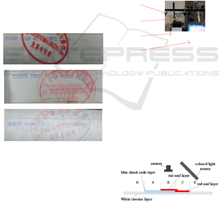
1 INTRODUCTION
Invoice Check Code is one of the important bases
for checking the authenticity of invoices. In the
process of invoicing, various uncertainties lead to
various degrees of corruption of invoice check codes
(as shown in Figure 1, the check codes are covered
by red seals). It is impossible for businesses to
distinguish the authenticity of invoices and bring
great difficulties to invoice reimbursement.
Therefore, the research on automatic recognition of
check codes covered by red seals will help to reduce
the investment of manpower and material resources
(Sonka M, Hlavác V, Boyle R, 2014).
In order to solve the problem of character
recognition in complex situations such as character
being covered by seals, some scholars have studied
it at present.To solve the problem of image
decolorization, H. Du et al. (Du H , He S , Sheng B ,
et al, 2015). Proposed a color-gray conversion
method based on regional saliency model. S. Liu
(Liu, SF, 2017) and others proposed to use Gabor
filter and S Obel operator to extract features first,
then K-means algorithm to segment regions, and
compare the characters to be recognized with
standard fonts. Finally, two character recognition
parameters, stroke cross-section and energy density,
were designed to increase recognition. Other
adaptability and robustness. (A Namane et al, 2010).
Proposed the method of using complementary
similarity measure (CSN) as classifier and feature
extractor to recognize degraded characters, which
enhanced the recognition ability of characters with
poor print quality. For non-uniform illumination
image, (Vo G et al, 2016). Proposed a robust matrix
decomposition method to solve the problem of
robust regression for binarization of images in strong
noise inhomogeneous background. This method
automatically segments binary images into
foreground and background regions in the case of
high observation noise level and uneven background
intensity. The experimental results show that the
method is more robust to high image noise and
uneven background. In order to improve the
efficiency of binarization, (Soua M et al, 2014)
proposed a hybrid binarization Keymens method
(HBK) parallel to Nvidia GTX 660 graphics
processing unit (GPU) (Soua et al. at the
International Symposium on Communication,
Control and Signal Processing, 2014). Our
implementation combines fine-grained and coarse-
Zhang, J., Kong, J., Wang, X. and Sun, W.
Research on Transmission Light and Recognition Algorithms of Invoice Check Code.
DOI: 10.5220/0008869804350443
In Proceedings of 5th International Conference on Vehicle, Mechanical and Electrical Engineering (ICVMEE 2019), pages 435-443
ISBN: 978-989-758-412-1
Copyright
c
2020 by SCITEPRESS – Science and Technology Publications, Lda. All rights reserved
435
grained parallel strategies to achieve the best. Good
GPU usage and efficient memory.
In summary, at present, the main method of
character recognition is to obtain images by front
illumination, and then design an algorithm to extract
characters from overlapping parts of characters and
seals. However, the examples in the above literature
do not include the cases of badly occluded
characters in seals as shown in Figure 1. In this
paper, the problem of identification of check codes
directly covered by red seals is studied. The color
distribution of the check code region and the
interaction between color and light are analyzed. A
scheme of imaging monochrome red light reverse
transmission is proposed, and the gray level of the
check code image is realized by three-channel
weighting method. Then the check code region is
located by two-way projection, and double
thresholds are carried out according to the
characteristics of the histogram of the gray image.
Value binarization, using vertical projection for
single character segmentation, and finally using
template matching method for character recognition.
(a)
(b)
(c)
Figure 1. Sample invoice with a check code covered by a
seal.
2 INVOICE IMAGING SCHEME
The color of opaque object imaging is determined by
the diffuse reflection and absorption properties
related to wavelength. The color of transparent
object or translucent object is determined by the
transmission properties related to wavelength. The
monochrome light can be used to illuminate the
color object to enhance the contrast of the
corresponding features of the detected object.
(Carsten Steger, et.al, 2017) Because of the three
colors of red (seal), blue (check code) and white
(invoice paper), RGB is used to illuminate the target
area, highlighting the characteristics of the target
area.
Figure 2 is an experimental platform for invoice
imaging. The RGB color camera has a resolution of
2592 1944 and a frame rate of 15 fps. The light
source is a monochrome strip light source. The
optional color light is red light with a wavelength of
600-700 nm, green light with a wavelength of 500-
550 nm and blue light with a wavelength of 400-480
nm, respectively
light source
camera
invoice
computer
Figure 2. Invoice image collection experiment platform.
2.1
Forward Lighting
The color of an object's forward illuminated image is
determined by the reflection property of its surface.
In order to understand the color distribution of the
invoice surface image, it is necessary to study its
reflection property. Fig. 3 is a schematic diagram of
the invoice forward illumination model. The camera
and light source are arranged on the front of the
invoice. In the vertical direction, there are three
layers of structure: red seal, blue check code and
invoice paper. In order to facilitate analysis, the
positive surface of invoice is divided into uncovered
area (A), covered area (B), only seal area (C) and
invoice blank area (D).
Fig 3. Forward illumination imaging schemati diagram.
ICVMEE 2019 - 5th International Conference on Vehicle, Mechanical and Electrical Engineering
436
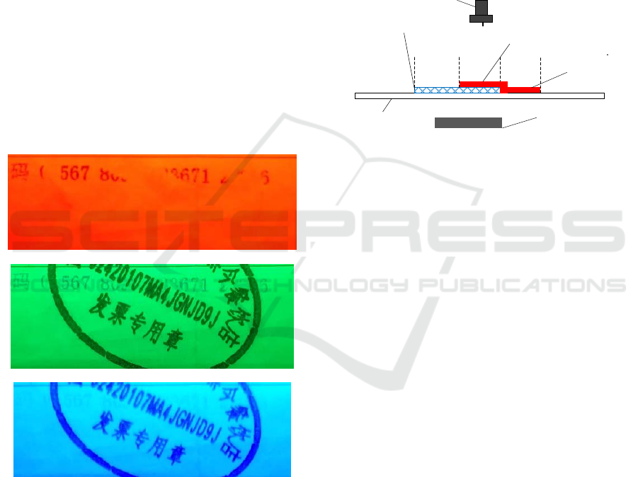
The invoice of Fig. 1 (a) is illuminated by red
light. The imaging effect is shown in Fig. 4 (a).
Because the blue calibration codes in Area A absorb
red light, the red seal and the white paper surface
reflect red light, so the calibration codes show black
color and obvious contrast; the red seal and the
white paper surface in the top layer of Area B, C and
D all reflect red light, and the blue calibration codes
in the bottom layer of the seal are not illuminated, so
they can not be displayed.
The invoice of Fig. 1 (a) is illuminated by green
light. The imaging effect is shown in Fig. 4 (b).
Because the red and blue check codes absorb green
light and the white paper reflects green light, the
image background is green and the seal and check
codes are black.
The invoice of Fig. 1 (a) is illuminated by blue
light. The imaging effect is shown in Fig. 4 (c).
Because both the check code and the white paper
surface reflect blue light, the seal absorbs blue light,
and the background of the image is blue, the check
code disappears and the seal highlights
(a) Results of red light illumination
(b) Results of green light illumination
(c) Results of blue light illumination
Fig 4. Forward illumination imaging result (for Fig. 1(a).
The experimental results show that the forward
irradiation imaging can not effectively eliminate the
influence of the seal, nor can it highlight the blue
check codes covered by the seal. Similar results can
be obtained for the invoices of Figure 1 (b) and (c).
2.2 Reverse Transmission
Reverse transmission imaging is suitable for
transparent or translucent objects. As the invoice
paper is carbon-free copy paper (Guanhao Gaoxin,
2013), when the backlight intensity is large enough,
it presents the characteristics of translucent objects,
so it can be imaged by the way of reverse
transmission illumination shown in Fig. 5. The
camera is on the front of the invoice and the light
source is on the back of the invoice.
white invoice
layer
blue check code layer
camera
colored light source
red seal layer
red seal layer
D A B C D
Fig 5. Reverse transmission imaging schematic diagram.
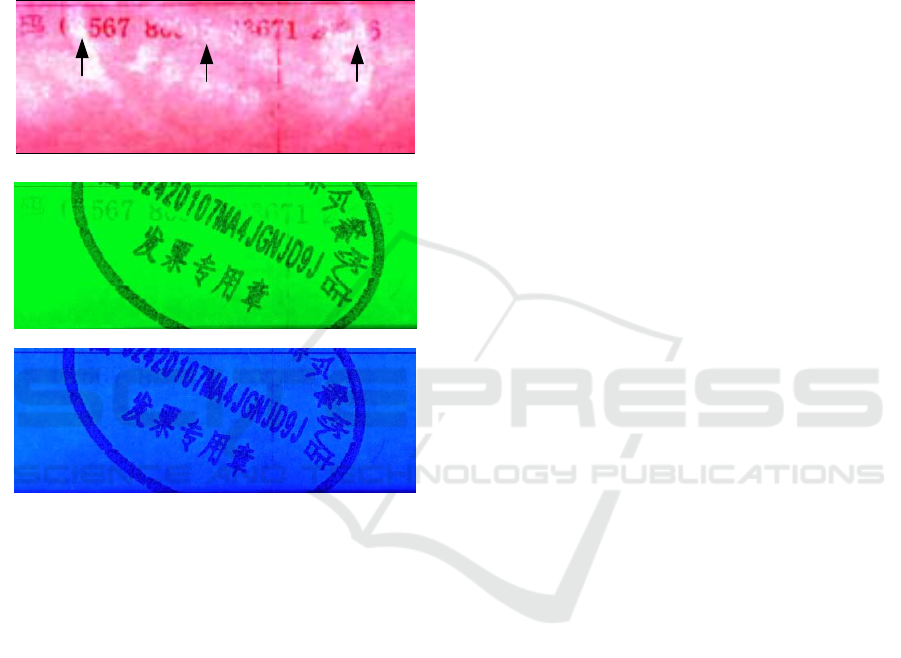
For Fig. 1 (a), the results of red light
transmission imaging are shown in Fig. 6 (a). White
paper will pass through red light, D area background
will appear red; Blue check code will absorb red
light, A area blue check code will appear black,
contrast is obvious; Red seal will pass through red
light, so the seal outline of B and C area will appear
red, although the blue check code covered by red
seal in B area will absorb part of red light. However,
the backlight has a large luminous surface, and the
seal ink increases the transparency of the invoice
itself to a certain extent. The red light will still pass
through the blue check code and the overlap area of
the seal, so that the red part of the seal (including the
cover check code indicated by the solid arrow in Fig.
6 (a) is highlighted as a whole, and it is slightly
brighter than the background red.
The green light transmission imaging effect is
shown in Fig. 6 (b). White paper absorbs green light
through green light, seal and check code. The whole
image presents a green background. The check code
and seal are black, and the covered part is not
prominent.
Using blue light transmission imaging effect as
shown in Figure 6 (c), white paper and blue check
codes all penetrate blue light; the seal absorbs blue
light, showing black, and the check codes are
submerged in the overall blue background.
Comparing the two irradiation models, we can
see that: (1) reverse transmission imaging needs
Research on Transmission Light and Recognition Algorithms of Invoice Check Code
437
stronger light; (2) forward irradiation imaging can
not highlight the characteristics of coverage check
codes in area B; (3) reverse red light transmission
can highlight the background, red seal and blue
check codes covered by seals, and it is advantageous
to enhance the contrast to a certain extent. For
further image recognition. Therefore, the invoice
image is obtained by the illumination method of
reverse transmission of red light.
(a) Results of red light transmission
(b) Results of green light transmission
(c) Results of blue light transmission
Fig 6. Result of reverse transmission imaging.
3 BINARIZATION OF CHECK
CODE IMAGE
After imaging with the above method, the covered
part of the check code can be displayed, but it is still
weak compared with the uncovered part. In order to
obtain the complete invoice check code, binarization
is needed to achieve the complete segmentation of
the check code.
In this paper, according to the color information
of the image, the three-channel gray value is
weighted to realize the image gray level, the two-
way projection is used to locate the check code area,
and the double threshold is used to binarize the gray
level image. In order to verify the effectiveness of
the algorithm, this paper uses the visual module
Visio Assistant of MATLAB and Labview.
3.1 Grayscale Image
In the color image acquired by the reverse
transmission of red light (Fig. 6 (a)), the check codes
show two colors: the uncovered check codes show
black color, and the seal-covered check codes show
bright white color, which shows the difference of the
check codes to a certain extent, but the strong
background color also reduces the contrast of the
check codes. The data of each channel should be
integrated and grayed to improve the contrast of the
target. Each pixel of a color image is the
corresponding red, green and blue components of
the color image in a specific spatial position. The
common gray-scale method is to weigh the RGB
images in each channel, and its formula is shown in
Formula (1).
12 3
,, ,,
f
xy a rxy a g xy a bxy
(1)
In the formula:
,
x
y
is the position of the pixel in
the image,
,
f
xy
is the grayscale image;
1
a
,
2
a
,
3
a
are weighted coefficients, they are all non-
negetive numbers and satisfy
123
1aaa
,
,rxy
,
,
g
xy
,
,bxy
are the image components
of the red channel, the green channel and the blue
channel of the image.
In order to select a reasonable grayscale function,
it is necessary to calculate the grayscale distribution
of each RGB channel image, and then determine the
weighted value according to the statistical
characteristics. Histogram is the most common
method of pixel statistics.
Figure 7 (a), (b) and (c) are gray image
histograms of red, green and blue channels
respectively, which express the number of gray
value pixels in each channel image. As can be seen
from Figure 7, the gray value of the red channel is
concentrated, which reduces the image contrast,
while the gray distribution of the other two channels
is relatively wide, which can show a better
brightness difference.
ICVMEE 2019 - 5th International Conference on Vehicle, Mechanical and Electrical Engineering
438
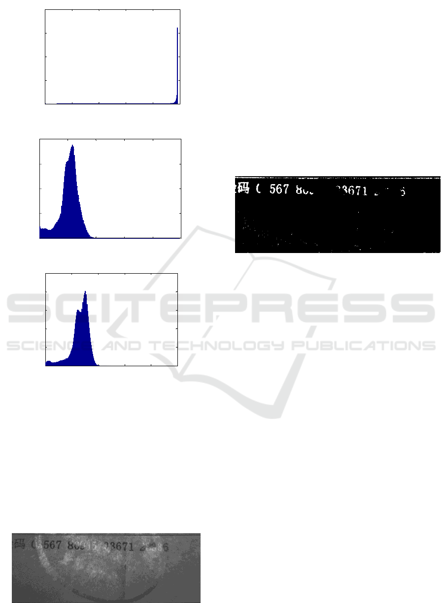
(a) Red channel histogram;
(b) Green channel histogram
(c).Blue channel histogram
Fig 7. RGB three-channel image.
Because the background color of the image is red,
in order to maximize the suppression of the
background color and reduce the interference of the
red channel, let
1
0a
, the coefficients of the other
two channels
2
0.7a
,
3
0.3a
the result of
weighted graying is shown in Fig. 8. It can be seen
from the figure that the contrast between the
overwritten check codes and the uncovered check
codes has been greatly improved.
Fig 8. Grayscale results.
3.2 Regional Positioning
Binarization is the most direct way to extract targets,
but due to the uneven illumination and background,
direct binarization will bring a lot of interference.
The interference can be greatly reduced by
localizing the parity-check code region and then
processing it. In order to locate the region, the
method of maximum inter-class variance (Liu J,
1993) is used to binarize figure 8. The result is
shown in Figure 9. The uncovered parity-check
codes and the lines above the parity-check codes are
extracted, and most of the background interference
is filtered out, which is conducive to the next
projection positioning.
Fig 9. Otsu binarization results.
Vertical and horizontal projection refers to the
sum of gray levels along the vertical and horizontal
directions of the image. If the image size is M * N
(M is the number of rows of the image and N is the
number of columns of the image), the vertical and
horizontal bidirectional projections are carried out
by using formulas (2), (3).
1
,
M
y
y
FF
x
xy
(2)
1
,
N
x
x
FFyxy
(3)
In the formula:
,
F
xy
is the pixel value of
image 9 at the point
,
x
y
,
y
F
x
is the vertical
projection vector,
x
F
y
is the horizontal projection
vector. The range of values of x and y is divided into
1,
x
N
,
1,yM
.
The result of bidirectional projection of Figure 9
is shown in Figure 10. In this paper, N = 648, M =
240.
0 52 104 156 208 260
0
0.5
1
1.5
2
x 10
6
Gray value
Number of Pixels
0 52 104 156 208 260
0
2
4
6
8
x 10
4
Gray value
Number of Pixels
0 52 104 156 208 260
0
2
4
6
8
10
x 10
4
Gray value
Number of Pixels
Research on Transmission Light and Recognition Algorithms of Invoice Check Code
439
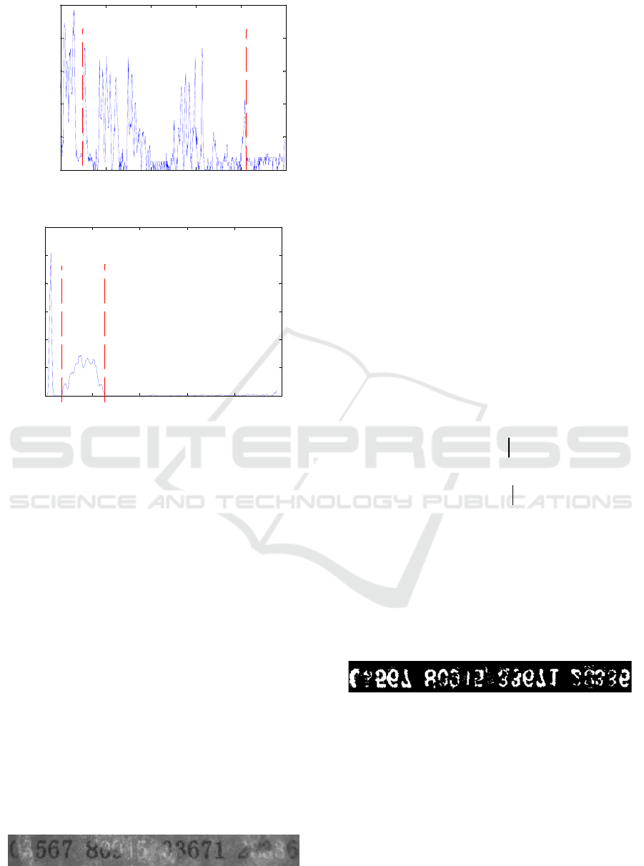
(a) Vertical projection
(b) Horizontal projection
Fig 10. Bidirectional Projection Results.
Vertical projection (Fig. 10 (a)) is used to
determine the left and right boundaries of the parity
code region. The algorithm steps are as follows:
(1) Set a valley threshold
1
T
, and traverse the
histogram from small to large. When the value is
less than
1
T
, record the gray level of the position as a
candidate valley.
(2) Setting a width threshold
2
T
, when the
number of gray levels continuously less than the
threshold
1
T
is greater than the threshold
2
T
, it is
marked as a continuous trough.
(3) Search from left to right (for Fig.10 (a),
1
T
=
766,
2
T
= 20) to find the column corresponding to
the end of the first continuous trough (point a in the
figure, its abscissa is 67), that is the left boundary of
the check code; search from right to left, the position
of the end of the first reverse continuous trough
(point B in the figure, its abscissa is 538), which
corresponds to the check. Code right boundary.
Fig 11. Location result.
3.3 Binarization
In the gray image, the invoice check code is divided
into two parts: the low gray level part which is not
covered and the high gray level part which is
covered. The number of gray level pixels in these
two parts is much less than that in the background.
The histogram of this kind of gray image presents a
single peak, so it is difficult to find the valley by
traditional methods, which makes it difficult to
segment the check code.
In this paper, according to the characteristics of
high and low distribution of target pixels in gray
image, a double threshold method is used to binarize
the image. The algorithm steps are as follows:
(1) The gray histogram
Tr
of the image is
acquired, and the maximum peak
max
T
and its
corresponding gray value
m
r
are determined by
traversal from the gray histogram.
(2) With the maximum peak value as the
demarcation line, the maximum gray value of
gradient is searched from left and right sides to the
middle respectively, and two thresholds
1
r
and
2
r
are
obtained by using formulas (4) and (5).
''
1
max
m
Tr Trr r
(4)
''
2
max
m
Tr Trr r
(5)
(3) Using
1
r
and
2
r
as double thresholds, image
11 is binarized according to formula (6).
In formula:
1
,
F
xy
and
,
f
xy
are binary
image and gray image respectively. After
binarization of image 11, the median filter with 3 *3
sliding window is used to remove the particle noise.
The result is shown in Figure 12.
Fig 12. Binary results.
From Figure 12, we can see that the binary image
is obtained by the above method, and the uncovered
check codes are extracted completely. For the
overwritten check codes, the extraction effect is also
good, which lays a good foundation for the
recognition of the subsequent check codes.
0 130 260 390 520 650
0
2000
4000
6000
8000
10000
Column number
Sum of pixels
a
b
0 49 98 147 196 245
0
2
4
6
8
10
12
x 10
4
Row number
Sum of pixels
c
d
ICVMEE 2019 - 5th International Conference on Vehicle, Mechanical and Electrical Engineering
440
4 CHARACTER
SEGMENTATION AND
RECOGNITION
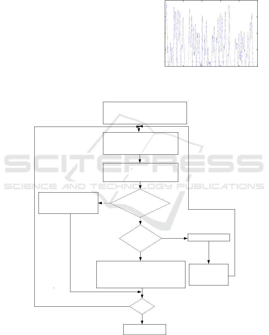
4.1 Single Character Segmentation
As shown in Figure 12, the binary characters are
fractured and cohesive. In this case, the method
based on character width and eigenvalue projection
can be used to segment the binary characters. If the
eigenvalue is used to represent the peak judgment
threshold
4
T
, the first valley value that satisfies the
width limitation condition is found after passing
through a peak beyond the eigenvalue from any
segmentation point, that is, the location of the next
segmentation point. As shown in Figure 13, the red
line in the vertical projection is the eigenvalue
4
T
=
514.
Fig 13. Vertical projection.
The left partition point P [1] of the first
digit 0 is taken as the starting point, and
it is taken as the current P [i]
Scanning from P [i] to the right, a
trough after a peak that exceeds
eigenvalue is found to be marked
as
3
T
Calculate the distance between
and P [i], and mark it as Width
Width<MaxW &&
Width>MinW
Judged as
background noise,
discarded directly
i>=10
Segmentation end
Character cohesion, search for the
narrowest part of the character into the
segmentation, at this time i = i + 2, and
Acts as the current segmentation point P [i]
Width<MinW
When judged as a character,
i= i+ 1 and acts as the
current segmentation point
P [i]
'
P
Width>MaxW
'
P
Y
Y
Y
N
N
N
Fig 14. Separation flow char.
0 100 200 300 400 500
0
2000
4000
6000
8000
Column number
Sum of pixels
Research on Transmission Light and Recognition Algorithms of Invoice Check Code
441
As shown in Figure 12, the parity code region
will have three largest interval regions (e.g. between
the fifth character and the sixth character). The
parity code is divided into four parts, and their
search and segmentation methods are similar.
According to the prior knowledge such as the
overall width of the check code region and the width
of a single character, the segmentation points of each
group of numbers can be searched by combining the
threshold of the continuous trough. Then, the
minimum width of the character MinW = 8 and the
maximum width MaxW = 19 are used as the
thresholds of the character width for single character
segmentation. Taking the first group of figures in
Figure 12 as an example, there are five figures,
forming 10 segmentation points P. With the initial
segmentation position P (Sonka M, Hlavác V, Boyle
R, 2014) as the starting point, search right. The flow
chart of the algorithm program is shown in Figure 14.
After vertical segmentation, the upper and lower
positions of characters have more or less space, and
then horizontal projection segmentation is carried
out to determine the upper and lower boundary
positions of characters. The result of segmentation is
shown in Fig. 15. The graph completely divides
every number of check codes and can be used as
input for next processing.
Fig 15. Segmentation results.
4.2 Character Recognition
Because the style of the check code is relatively
fixed, this paper uses the template matching method
(Wei L, He X, Chao T, et al, 2017) with higher
recognition rate to recognize. The template and the
character to be recognized are both black and white
characters. Before recognition, the character to be
recognized is normalized into 34 x 60 pixels by
bilinear interpolation method, and then matched with
the template. The specific steps are as follows:
(1) Calculate the number of white pixels T and U of
the character to be recognized, and then calculate the
number of white pixels V of image 1 by logical
"and" operation of template image and character
image to be recognized.
(2) The character image to be recognized and image
1 are processed by logic XOR operation to get image
2 and calculate the number of white pixels X in
image 2.
(3) The template character image and image 1
are processed by logic XOR operation to get image
3, and the number of white pixels W in image 3 is
calculated.
(4) Computation of similarity coefficient Y
according to formula (6)
222
2
V
Y
T TUV U TUV V TUV
WX
TU
(6)
In the formula:
3
TUV
TUV
For each specific character, the similarity
coefficients of 10 templates are calculated, and the
template corresponding to the maximum similarity
coefficient is taken as the recognition result of the
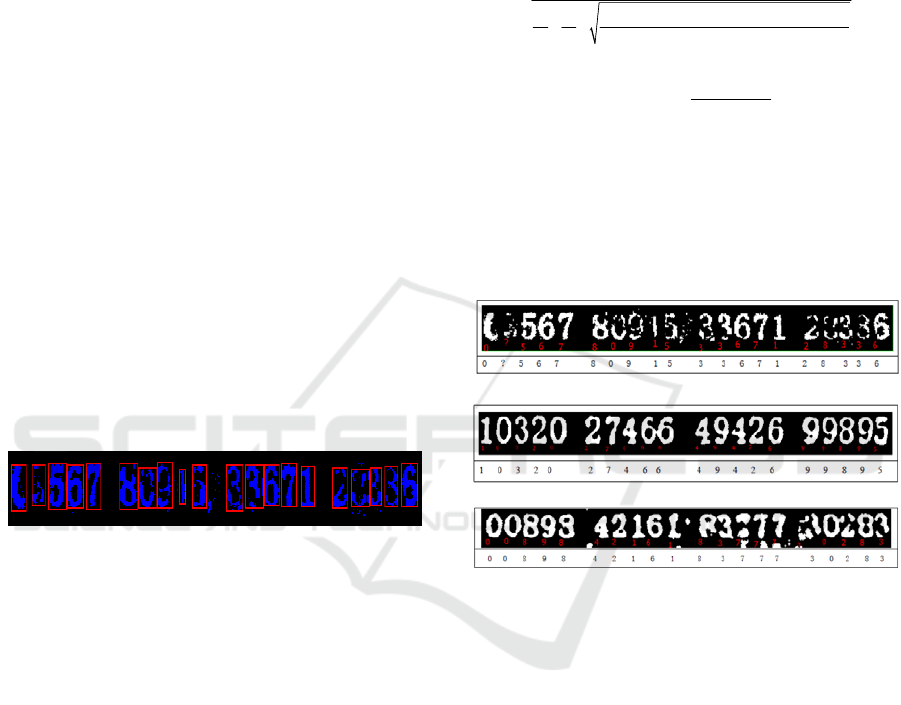
character to be recognized. According to the above
algorithm, the recognition results of some images in
this paper are shown in Figure 16.
(a)
(b)
(c)
Fig 16. Partial Sample Recognition Results.
The experimental results show that the method
can eliminate the influence of red stamps and get
better recognition results for invoices with less
serious red stamps, as shown in Fig. 16 (b), (c). But
for Figure 1 (a), because the red seal is very serious,
and part of the blue check code fades, there are some
flaws in the recognition effect part, resulting in the
second digit to be recognized, which is also what
this algorithm needs to be further studied.
In conclusion, the proposed model and image
processing algorithm can recognize the check codes
covered by logarithmic seals. The experimental
results show the effectiveness of the algorithm.
ICVMEE 2019 - 5th International Conference on Vehicle, Mechanical and Electrical Engineering
442

5 CONCLUDING REMARKS
Aiming at the problem of recognition of blue check
codes covered by red seals on ordinary VAT
invoices, this paper studies and analyses the three
steps of image acquisition, image binarization and
character recognition. In the phase of image
acquisition, considering the color distribution of the
check code area, monochrome red light is used to
transmit the image from the back of the invoice to
highlight the cover check code. In the binarization
stage, according to the gray histogram of R, G and B
channels, the weighted method is proposed to gray
the image, and the two-way projection method is
used to locate the check code region, and a double
threshold binarization method is proposed. In the
character recognition stage, a single character is
segmented according to the width of vertically
projected characters. Finally, a template matching
method is used for character recognition. The
experimental results show that this method can solve
the problem of extraction and recognition of check
codes when the check codes of invoices are covered
by red seals, and improve the accuracy of
identification of such defective check codes.
REFERENCES
Carsten Steger, Markus Ulrich, Christian Wiedemann.
Machine Vision Algorithms and Applications [M].
Beijing Tsinghua University Press, 2017: 12-13.
Du H, He S, Sheng B, et al. Saliency-Guided Color-to-
Gray Conversion Using Region-Based Optimization
[J]. IEEE Transactions on Image Processing, 2015,
24(1):434-443.
Guanhao Gaoxin. Guanhao Gaoxin has won nearly 100
million yuan of duplicate paper sheets [J]. China Paper.
Liu J. The Automatic Thresholding of Gray-Level Pictures
Via Two-Dimensional Otsu Method [J]. Acta
Automatica Sinica, 1993, 19(1).
Liu, SF (Liu Shufeng) 1; Shen, SH (Shen Shaohong) 2;
Sun, ZY (Sun Zhiyuan) 3; IEEE.Research on Chinese
Characters Recognition in Complex Background
Images [J].2017 2ND INTERNATIONAL
CONFERENCE ON IMAGE, VISION AND
COMPUTING (ICIVC 2017), 2017,: 214-217.
Namane, A.;Maamoun, M.;Soubari, E.H.;Meyrueis,
P..CSM-based feature extraction for degraded machine
printed character recognition [A].2010.
Sonka M, Hlavác V, Boyle R. Image Processing, Analysis
and Machine Vision [J]. Journal of Electronic
Imaging, 2014, xix (82):685–686.
Soua M, Kachouri R, Akil M. GPU parallel
implementation of the new hybrid binarization based
on Kmeans method (HBK) [J]. Journal of Real-Time
Image Processing, 2014:1-15.
Vo G, Park C. Robust Regression For Image Binarization
Under Heavy Noises and Nonuniform Background [J].
Pattern Recognition, 2016, 81.
Wei L, He X, Chao T, et al. Handwritten Numbers and
English Characters Recognition System[C]// 2017.
Research on Transmission Light and Recognition Algorithms of Invoice Check Code
443
