
Differential Control Strategy Research of Wheeled Electric Drive
ADT Mining Truck
Huilai Sun
1, 2, a
, Pengbo Liu
2, b, *
, Yong Wang
1, c
, Yuanyuan Song
2, d
, Zeying Li
2, e
and Guoming Yao
2, f
1
Institute of Automation, Qilu University of Technology (Shandong Academy of Sciences), Jinan 250101, China.
2
College of Mechanical and Automotive Engineering, Qilu University of Technology(Shandong Academy of Sciences),Jinan
250353,China
b
Corresponding author: pengbosdu@163.com
c
wyong0101@qq.com
d
songyuanyuan1028@126.com
e
18364195056@163.com
f
2776716601@qq.com
Keywords: Articulated mining truck, wheeled electric drive, electric differential, control strategy, slip rate.
Abstract: Aiming at the special structure and steering characteristic of wheeled electric-driven articulated
underground mining truck, a differential control strategy which takes the equal slip rate as control target was
given. The kinematic and dynamic model of electric-driven mining ADT was established and the movement
relationship and stress condition of the driving wheels were analyzed during steering. Acceleration sensors
in the sample ADT were used to test the actual speed of the vehicle. Results show that the filtered signal has
small delay and fast response and can be directly used to estimate the speed. Equal slip rate control strategy
is superior to equal torque control strategy because it can make full use of the ground adhesion coefficient
and reach reasonable distribution of drive power. Two sides wheel slip rate can be stable -0.08 and sliping
situation is avoided in experimental turning. This control strategy has practical effect for reducing tire wear
and improving driving power utilization.
1 NTRODUCTION
The operating condition of articulated underground
mining trucks is complex, such as narrow road,more
corners, wet and slippery ground, and the vehicle
body load quality is large. In order to adapt to the
narrow underground environment, articulated
steering of front and rear body is used, and full
wheel drive is used to increase traction force. The
35t wheeled electric-driven articulated underground
mining truck is newly developed by University of
Science and Technology Beijing,which is the only
one using diesel-electric power at home and abroad,
wheel drive, and independent control of each drive
wheel torque and speed.
Unlike mechanical transmission, there is no
differential mechanism on the wheeled electric-
driven vehicle. In order to ensure that there is no
sliping between the drive wheels during steering, the
vehicle loses ground traction and excessive tire wear
(Liu Weixin, 2001; M Canale, L Fagiano, M
Milanese, et al, 2007; YU Houyu, Huang Miaohua,
2011; Wang Junnian, Wang Qingnian, Song
Chuanxue, et al, 2010) It is necessary to adopt
accurate model and effective strategy for differential
control. Differential control is one of the key
technologies for the design of wheeled electric-
driven vehicle.
There are many researches on electronic
differential control in passenger cars (Li Bin ,Yu Fan,
2008; A G Nalecz, A C Bindemann, 2003; Y H Ge,
C S Li, G Z Ni, 2003) ,they established kinematics
relationship of each drive wheel mainly through the
Ackerman model to control the wheeled electric
motor and developed differential control strategy
(Fredriksson, Andreasson, Laine, 2004; Umesh
Kumar Rout, et.al, 2013; Zhang Daisheng, Li Wei,
2002; Wang Renguang, Liu Zhaodu, Qi Zhiquan,et
al, 2007). At present, the rear wheel drive is used for
wheeled electric-driven underground mining truck at
home and abroad, and the steering differential
adopts the equal-torque control strategy. The equal-
70
Sun, H., Liu, P., Wang, Y., Song, Y., Li, Z. and Yao, G.
Differential Control Strategy Research of Wheeled Electric Drive ADT Mining Truck.
DOI: 10.5220/0008868300700077
In Proceedings of 5th International Conference on Vehicle, Mechanical and Electrical Engineering (ICVMEE 2019), pages 70-77
ISBN: 978-989-758-412-1
Copyright
c
2020 by SCITEPRESS – Science and Technology Publications, Lda. All rights reserved
torque control strategy can not meet the
requirements of the vehicle's passing ability on a
complex roads, and it is prone to inconsistent
operation between the wheels, which consumes
additional power and wears the tires, resulting in
deterioration of steering and handling performance.
Therefore, it is necessary to put forward the driving
control strategy with sliding rate as the control target,
coordinate and control the driving force of each
wheel, and avoid the above situation. The control
strategy with consistent slip rate needs to calculate
the slip of each wheel by monitoring the vehicle
speed and the driving wheels ' rotational velocity,
and then control the torque to adjust the slip rate of
each drive wheel ,so that they tend to be
consistent(Shen Jun,Song Jian,Wang Huiyi, 2007).
And for full-wheel drive articulated electric-driven
vehicles, how to obtain accurate absolute speed is
also a key issue, and now there is no good solution
for such articulated vehicles.
Taking the steering condition of 35t wheeled
electric-driven articulated underground mining truck
as the research object, this paper establishes
kinematics and dynamics model of the vehicle, and
analyzes the relationship between every wheel’s
rotation speed and torque. The longitudinal
acceleration of the prototype is tested with the
acceleration sensor in real time and Kalman filter is
used to obtain the effective absolute speed of the
vehicle. A multi-body dynamics simulation platform
including steering wheel angle input model, wheeled
electric drive model and underground mine vehicle
virtual prototype model were established, and a joint
simulation of vehicle steering differential conditions
was carried out with the sliding rate controller ,
takes the equal slip rate as control target. And the
results of equal torque control strategy are compared
and analyzed.
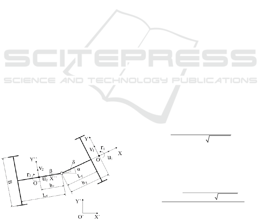
Figure 1. Vehicle kinematic model.
2 MATHEMATICAL MODEL
ESTABLISHMENT
2.1 Kinematics Model
In order to accurately describe the slide rate of each
wheel, a vehicle kinematics model needs to be
established. As shown in Fig 1, the coordinate
system OXYZis an absolute coordinate system
fixed on the ground. OXYZ and OXYZare the
dynamic coordinate systems whose coordinate origin
is fixed on the center of mass of the front and rear
vehicle bodies respectively. X, X axles coincide
with the longitudinal axes of the front and rear
bodies, and δ denotes the angle between the front
and rear bodies.B denotes the distance between the
front and rear body, Lf denotes the distance between
the front wheel center and the hinged joint, Lr
denotes the distance between the rear wheel center
and the hinged joint, denotes is the distance between
the front body mass center and the hinged joint, and
hr denotes the distance between the rear body mass
center and the hinged joint. u1, v1, r1 denote the the
front car body’s longitudinal velocity, transverse
velocity, and transverse angle velocity around the Z
axis respectively, while u2, v2, r2 denote the the rear
car body’s longitudinal velocity, transverse velocity,
and horizontal angle velocity around the Z axis
respectively. The sum of r1 and r2 denotes the angle
change rate between the front and rear bodies, that is
21
rr
(1)
From the motion relationship of each wheel,
regarding the steering angle as a known parameter,
1
2
(1 )
2 cot 2 1 cot
fl
fr
B
uu
LL
(2)
uflu
fl
, ufr, url, urr denote longitudinal velocity of
the center of the left front wheel, right front wheel,
left rear wheel and right rear wheel respectively.
And derive the slip rate expression of the wheels
1
2
(1 )
2 cot 2 1 cot
fr
fl
B
wR u
LL
S
wR
(3)
Sflu
fl
, Sfr, Srl, Srrs
fl
s
fr
denote the slip rate of the
left front wheel, right front wheel, left rear wheel
and right rear wheel respectively. w denote the
wheel angular speed to define the speed, and
Differential Control Strategy Research of Wheeled Electric Drive ADT Mining Truck
71
propose the accurate method of estimationing the
speed .
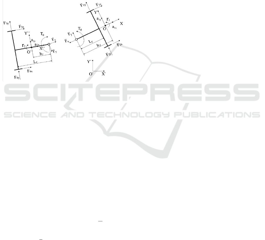
2.2 Dynamic Model
The dynamic model of wheeled electric-driven
articulated underground mining truck is established
to analyze the force relationship between the vehicle
and the ground, so as to control the torque of the
wheeled traction motor and monitor the speed of the
wheel side. Select 3 degrees of freedom for
longitudinal, lateral, and yaw-moment to establish a
vehicle dynamics model, as shown in Figure 2.
Figure 2 .Vehicle dynamic model.
In Fig 2, a1x and a1y are the acceleration along
the X axis and the Y axis at the center of the front
body; a2x, a2y are the accelerations along the X
axis and the Y axis at the center of the rear body;
Fix, Fiy denote the tangential and lateral forces face
the i wheel respectively(i = 1,2,3,4); To is the
steering internal torque between the front and rear
bodies; Fx and Fy are the forces of the hinged point
along the X axis and the Y axis, respectively.
Based on the relative relationship between the
front and back of the vehicle body in Fig 2,
considering the parameters such as the quality
characteristics, acceleration, and moment of inertia
of the vehicle, derive the torque balance equation of
the vehicle body around the X, Y, Z, X, Y, and Z
axes.
fyxxffyyzz
hF
B
FFLhFFTrI
2
)())((
1221011
(4)
r
h
x
F
y
F
r
L
r
h
y
F
y
F
B
x
F
x
FTr
zz
I )sincos())(
43
(
2
)
43
(
02
(5)
xxyx
FFFFvrum
432222
sincos)(
(6)
yyyx
FFFFurvm
432222
cossin)(
(7)
From the results of formula, it is known that
adjusting the driving force of each wheel and the
articulated angle of the front and rear body can
control the longitudinal lateral speed of the vehicle
body during the steering and change the sliding rate
of each drive wheel. However, The above
relationship can not accurately describe the quality
characteristics of the vehicle itself under dynamic
conditions, and the calculation of slip rate is not
accurate enough. Subsequent numerical analysis
uses multi-body dynamics software to consider the
impact of the quality characteristics and operating
status of the vehicle on the slip rate.
3 MULTI-BODY DYNAMICS
MODEL ESTABLISHMENT
The articulated truck tire is the only part that
connects the body and the road. Its force,
deformation and motion response have a great
influence on the movement of the vehicle. The
traditional mathematical model is difficult to
describe the characteristics of the vehicle-tire-road
coupling model accurately. On the basis of vehicle
kinematics, this paper uses multi-body dynamics
software to consider the quality characteristics and
operation status of the vehicle. The shading and
rendering model is shown in Fig 3. Combined with
the above analytical dynamics, the force and torque
of the tire in contact with the ground are calculated
using the UA tire model, which accurately reflects
the slide rate and realizes the driving control effect.
The vehicle drive model joint simulation is
performed with the multi-body dynamics model,
including the motor drive model and the steering
wheel input model. The output torque of the motor
drive model drives the wheel, and the actual wheel
speed is fed back to each motor drive model by the
model. The rigid connection between the motor and
the wheel is simulated, and the deceleration and
torsion are carried out through the wheel side
reducer model. The line displacement of the steering
cylinder and the driving torque of the wheel are used
as the vehicle control signals to simulate the steering
wheel angle and throttle pedal input when the driver
drives the vehicle. The output of the model is the
vehicle operating state parameters, including speed,
steering angle, wheel speed, slip rate, etc.
ICVMEE 2019 - 5th International Conference on Vehicle, Mechanical and Electrical Engineering
72
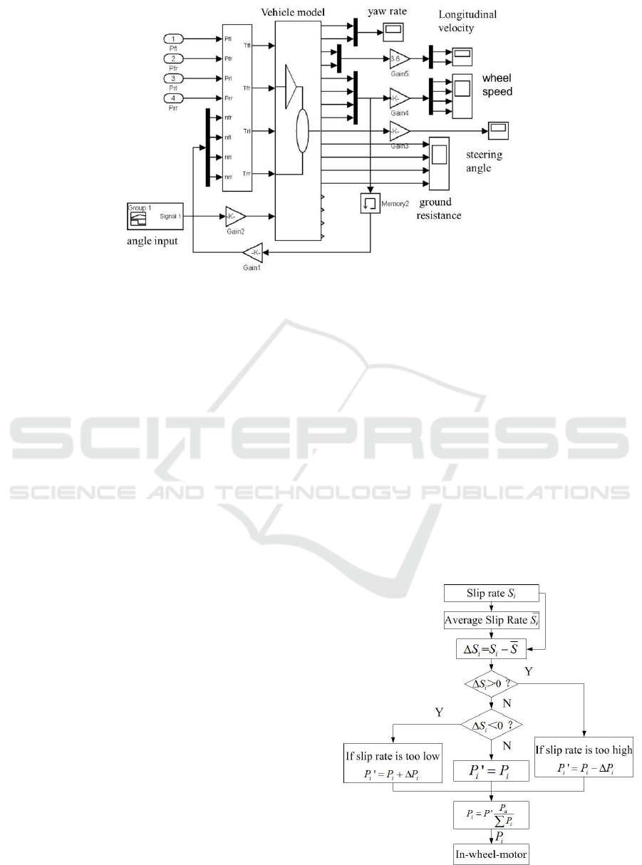
Figure 3 .Vehicle driving model.
4 CONTROL STRATEGY BASED
ON CONSISTENT SLIP RATE
The former mentioned vehicle driving model is also
a framework for adopting different strategies for
control and analysis. The consistent slip rate control
strategy is to allocate torque and power according to
the slip rate’s changes of each wheel under different
conditions (Chen Dong, Xu Yin, Liang Huajun, 2013;
Wang Renguang, LiuZhaodu, Qi Zhiquan, et al, 2006) .In
this paper, the average slip rate of four wheels of
articulated vehicles is taken as the target slip rate,
the target slip rate and the slip rate of each wheel is
transmitted to the power distribution module in real
time. Power distribution module based on the
deviation of per wheel’s actual slip rate from Target
slip rate. Calculate the power and speed that each
wheel should allocate, adjust the torque and speed of
each wheel through the motor drive module, and
control that the sliding rate of each wheel is within
ideal range and eventually tends to be the same. The
control flow is shown in Fig 4.
5 TEST ANALYSIS
5.1 Real Vehicle and other Torque
Control Test
In order to evaluate the application effect of the
control strategy, the actual vehicle test and joint
simulation were carried out. In the test,
comprehensive speed estimation and analysis is
carried out, which fully reflects the acceleration,
deceleration and uniform speed. The design test
vehicle is gradually accelerated after 5s start. After
reaching the stable speed, it will travel at a constant
speed along the fixed circumference and keep the
steering wheel angle for two turns. Once again, the
vehicle is slowly and continuously accelerated, and
after the limit safety speed, the vehicle is slowly
braked to reduce the speed until the vehicle stops,
and the test is over. The entire process includes
acceleration, turning, uniform steering and
deceleration. Fig 6 and Table 1 show the test vehicle
and vehicle assembly parameters respectively. Fig 5
shows the obvious trace of the circular car mark on
the cement road.
Figure 4. The slip ratio control flow chart.
Differential Control Strategy Research of Wheeled Electric Drive ADT Mining Truck
73
Table 1. Assembly parameter.
Assembly
parameter
Numerical value
engine
Rated power (speed)/KW(n·min
-1
)
399(2100)
Traction motor
rated power / KW
90
Rated torque / Nm
1200
reducer
Reduction ratio
44
Tire
29.5R29
quality
Load mass /t
35
Curb quality /t
29
Figure 5. Testing field of 35 tons electric drive
underground articulated mining truck.
In order to fully evaluate the control strategy
effect and collect signals, the test uses LMS
SCADAS MOBILE SCM05 signal acquisition card,
and the sensor sampling frequency is 2560Hz, which
meets the test requirements. The INS is installed at
the center of the front and rear axles to measure the
acceleration and angular velocity of the three
orthogonal axes of the front and rear bodies. The
rotary encoder is installed under the steering column
of the steering wheel to measure the input angle of
the steering wheel. The angular displacement sensor
is installed at the hinge point to measure the front
and rear vehicles. The articulation angle between the
bodies is shown in Fig 6. The signals such as the
speed and current of the engine, generator and motor
are directly output by the CAN bus, which can be
easily collected by the USBCAN interface.
Figure 6. Sensor installation position.
5.2 Vehicle Speed Estimation Based on
Kalman Filtering
In the slip rate control, the vehicle speed needs to be
specifically estimated, and the wheel speed signal
must be filtered after removing the coarse error and
the measurement error of the system itself, and the
traditional vehicle speed estimation method is not
applicable to the all-wheel drive vehicle: signal
noise. The lower ratio will result in a large error in
the direct integration of the longitudinal acceleration
signal, which is easy to diverge; the method of
obtaining the vehicle speed using the non-driving
wheel speed is not applicable to the all-wheel drive
of the vehicle. In this paper, the longitudinal
acceleration signal and the wheel speed signal are
used as input, and the Kalman filter algorithm is
used to estimate the front and rear body speeds. The
filtering process starts from the known initial value
of the state and the initial value of the state
covariance matrix, and filters and estimates the input
wheel speed. The velocity estimation process of
Kalman filtering algorithm consists of two parts:
prediction and calibration, which includes state
equations and observation equations.
)()()()1( kwkxkAkx
(8)
)()()()( knkxkBkz
(9)
Which
()
()
x(k)
e
e
ak
vk
,
()
()
Z(k)
m
ak
kR
Where ae, ve represent the estimated values of
longitudinal acceleration and longitudinal vehicle
speed, respectively, am, ω represent the
experimental values of longitudinal acceleration and
wheel angular velocity, R represents the rolling
radius, Δt represents the time interval, and w1, w2
represent the system noise, na, nv denotes
ICVMEE 2019 - 5th International Conference on Vehicle, Mechanical and Electrical Engineering
74
measurement noise, system noise and measurement
noise are Gaussian white noise with known
statistical information. The estimated vehicle speed
after Kalman filtering is of great significance to the
specific implementation of the control strategy. To
represent the true value of the rolling radius,
Gaussian white noise can be added based on the
actual fluctuation amount.
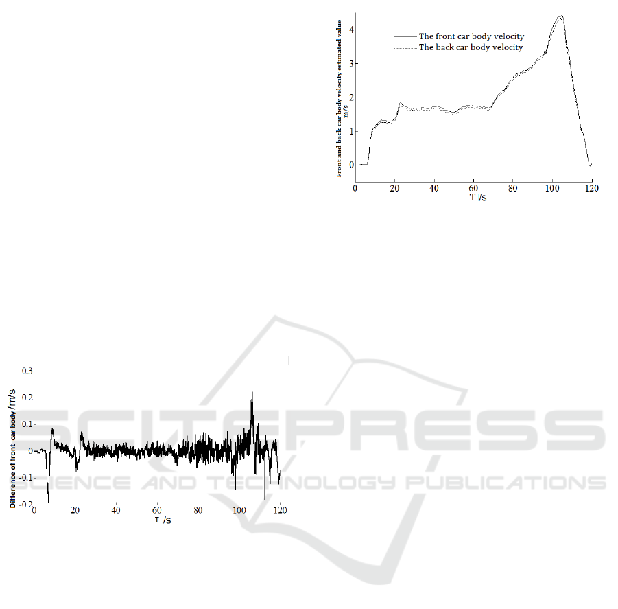
Figure 8 is the curve of the longitudinal velocity
estimation and measured value of the front body
after the filtering process. To see the difference
between the two is shown in Fig 9. The analysis
shows that the acceleration phase of 5~25s is large,
the difference between the two is large, the
maximum difference is 0.19m/s; the difference in
the steady steering phase is not large, and the
acceleration speed reaches the maximum value of
4.5m/s and starts to decelerate. The error is large,
0.2m/s. Generally speaking, in the steady-state
steering phase, the difference between the two is
small, and the more uniform the data, the more
consistent the data is.
Figure 7. Difference of front car body longitudinal
velocity estimated and measured value.
Similarly, the estimated value of the rear body
speed is shown in Fig 8. The estimated speed of the
front body is greater than the estimated speed of the
rear body, and the over-range is about 5%. In the
subsequent analysis, the average vehicle body speed
can be used as the vehicle speed, and the slip rate of
each wheel can be calculated.
Figure 8. Front and back car body longitudinal velocity
estimated value.
As can be seen from the above comparison, the
Kalman filtering method is applicable to three
situations of acceleration, braking deceleration and
uniform velocity. The filtered signal has a small
delay, a fast response speed and better smoothing
effect, and the effect is obvious at a constant speed
driving stage. The filtered signal can be used to
directly estimate the speed of the vehicle.
5.3 Simulation and Comparison of
Equal Slip Rate Control
The control strategy is simulated jointly by using the
multi-body dynamics simulation platform of the
whole vehicle, while the equal torque control
strategy is adopted in the real vehicle, which needs
to be verified by the multi-body dynamic model
under the equal torque control strategy to
demonstrate the accuracy of the multi-body dynamic
model. Then the simulation of equal slip rate
strategy is carried out. As mentioned earlier, the
hinged vehicle is steadily accelerated to a speed of
15 km / h after starting and steering at a uniform
speed. In the process of acceleration and uniform
steering, the torque and slip rate data of the two
wheels on the same side have little difference. In
order to make the diagram clear, the simulation data
of the left and right rear wheels and the inner wheels
are selected for analysis. The measured slip rate and
simulation slip rate are shown in Fig 9.
Differential Control Strategy Research of Wheeled Electric Drive ADT Mining Truck
75
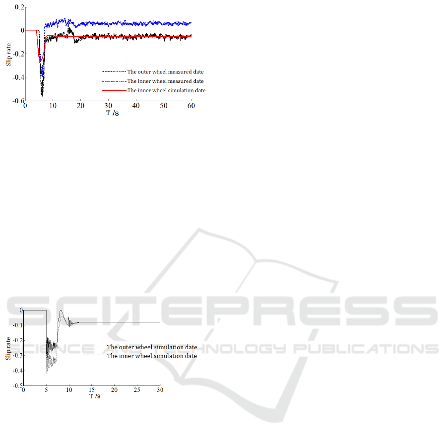
Figure 9. Slip rate under equal-torque control strategy.
It can be seen from Fig 10 that the driver
stabilizes the accelerator pedal after 25s under the
constant torque control strategy, but the torque of the
inner and outer wheel motor is basically the same
during the whole process, while the multi-body
dynamics simulation model rapidly enters the stable
state with the measured data, and finally stabilizes at
680N·m. The above data verify the accuracy of the
multi-body dynamics model and can reflect the
motion of the vehicle under different strategies.
After changing the system model into the equal slip
rate control strategy, the slip rate of the outer and
inner wheels is shown in Fig 10.
Figure 10. Slip rate under equal slip rate control.
Under the equal slip rate control strategy, the
automatic distribution torque of the system quickly
enters the steady turning condition, so the result of
the first 30s can be discussed. After the turning
instruction input and the torque adjustment of the
system, the slip rate of the inner and outer side
wheels can be stabilized to -0.08, there is no
slippage, which increases the utilization of adhesive
force.
6 CONCLUSION
This paper takes the steering condition of 35t
wheeled electric-driven articulated underground
mining truck as the research object. The main results
are as follows:
(1) The multi-body dynamic model and
kinematic model are in good agreement with the test
data of the real vehicle, which can effectively reflect
the motion of the vehicle under various working
conditions. The Kalman filter speed estimation result
has the advantages of small error and good real-time
performance, which can accurately reflect the slip
rate and other data under each control strategy.
(2) The differential speed control strategy with
the equal slip rate is superior to the equal torque
control strategy for wheeled electric-driven
articulated underground mining truck, which can
make full use of the adhesion coefficient, avoid type
wear when being dragged and skidded, reduce the
fuel consumption.
ACKNOWLEDGMENTS
Thanks to Li Yanqiang of Institute of Automation,
Shandong Academy of Sciences. This study is based
on joint scientific research projects ‘Research on
Path Planning and Path Following Control Method
of Auto-driving Electric Vehicle Based on
Reinforcement Learning (2018BSHZ0011), and
Research on Key Technologies of Low Cost and
High Precision Unmanned Driving for Intelligent
Electric Vehicles in Specific Areas
(2017GGX50107).
REFERENCES
A G Nalecz, A C Bindemann. Investigation into the
Stability of Four Wheel Steering Vehicle
[J].International Journal of Vehicle Design, 2003,
9(2):159~178.
Chen Dong, Xu Yin, Liang Huajun. A study on the
electronic differential control for hybrid electric
vehicle with in wheel motor rear drive [J].Automotive
Engineering, 2013, 35(1):47~50.
Fredriksson, Andreasson, Laine. Wheel force distribution
for improved handling in a hybrid electric vehicle
using nonlinear control [J]. Decision and Control,
2004, 8 (4):40~45.
Li Bin, Yu Fan.Vehicle yaw dynamics through combining
four-wheel-steering and differential braking [J].
Transaction of the Chinese Society for Agricultural
Machinery, 2008, 39 (12): 2~6.
Liu Weixin. Automobile Design [M].Beijing: Tsinghua
University Publishing House.2001.
M Canale, L Fagiano, M Milanese, et al. Robust vehicle
yaw control using an active differential and IMC
ICVMEE 2019 - 5th International Conference on Vehicle, Mechanical and Electrical Engineering
76

techniques [J].Control Engineering Practice, 2007, 21
(15): 923~941.
Shen Jun,Song Jian,Wang Huiyi. Obtaining the Optimal
Slip Ratio of the Road with Wavelet [J]. Transaction
of the Chinese Society for Agricultural Machinery,
2007, 38 (7):30~31.
Umesh Kumar Rout, Rabindra Kumar Sahu, Sidhartha
Panda. Design and analysis of differential evolution
algorithm based automatic generation control for
interconnected power system [J].Electral Engineering,
2013 (4):409~421.
Wang Junnian, Wang Qingnian ,Song Chuanxue, et al.
Co-simulation and Test of Differential Drive Assist
Steering Control System for Four-wheel Electric
Vehicle[J]. Transaction of the Chinese Society for
Agricultural Machinery, 2010, 41 (6):8~13.
Wang Renguang, Liu Zhaodu, Qi Zhiquan,et al. Research
on model construction of tire friction and slip rate[J].
Transaction of the Chinese Society for Agricultural
Machinery, 2007, 38(7):28~34.
Wang Renguang, LiuZhaodu, Qi Zhiquan, et al. Vehicle
Reference Speed Determination Using Adaptive
Kalman Filter Algorithm [J]. Transaction of the
Chinese Society for Agricultural Machinery, 2006, 37
(04): 9~11+41.
Y H Ge, C S Li, G Z Ni. A Novel Control System of PM
Brushless In Wheel Motors Used for EV [C]. Sixth
International Conference on Electrical Machines and
Systems, 2003, (2):592~595.
YU Houyu, Huang Miaohua. Experimental Research of
Electronic Differential Control for In-wheel Motor
Drive Electric Vehicle [J]. Journal of wuhan university
of technology, 2011, 33 (5): 148~151.
Zhang Daisheng, Li Wei. Simulation for slip ratio of an
automobile antilock-braking system based on fuzzy
logic control method [J]. Transaction of the Chinese
Society for Agricultural Machinery, 2002, 33 (2): 29~
31.
Differential Control Strategy Research of Wheeled Electric Drive ADT Mining Truck
77
