
Analysis and Research on Defrosting Ventilation Pipe Deformation of
Automobile
Guangming Li
1, 2
, Congrui Zuo
3, a, *
, Yi Ma
1, 2
and Qike Huang
1, 2
1
Department of Mechanical and Energy Engineering, Shaoyang University, Shaoyang 422000,China
2
Key Laboratory of Hunan Province for Efficient Power System and Intelligent Manufacturing, Shaoyang
University,Shaoyang 422000,China
3
Institute Of Thermal And Energy Metrology, Hunan Institute Of Metrology And Test ,Changsha 410000,China
Keywords: Car, defrosting ventilation pipe, Deformation, The finite element.
Abstract: According to the market feedback, automobile defrosting ventilation pipe does not fit in the top 10 of
xiangtan geely automobile market quality problems. According to the detection of vehicles in this condition,
the reason for the deformation of automobile defrosting ventilation pipe position is that the gap between
instrument cover and ventilation pipe is less than 4mm. Ventilation tube ends around not level off, the
present state of collapse, and the intensity of this state collapse is due to the lack of overall deformation, for
deformation reasons of automobile ventilation pipe outlet increase 11 on the back of the improved design
scheme of reinforcement, using the method of three-dimensional modeling, design parameters, according to
auto defrost ventilation tube through the Pro/E 3 d software to complete the ventilation pipe before and after
the improvement model, using ANSYS Workbench software of finite element analysis was carried out on
the ventilation pipe before and after improvement, the maximum deformation analysis ventilation pipe
outlet, After the improvement, the deformation amount decreased from 10.643mm to 10.283mm, and the
maximum stress value of the ventilation pipe decreased from 85.783MPa to 55.781MPa, less than the
ultimate strength of 70MPa, verifying the rationality of the improved design, Solve the quality problem for
the enterprise, have very good reference value.
1 INTRODUCTION
According to the feedback from the market, the
defrosting ventilation pipe on the instrument table is
deformed, which affects the product quality and
brand image of the vehicle. Therefore, the
elimination of defrosting defrosting ventilation pipe
on the instrument has become an improvement
object. According to statistics: in January 2018, the
problem of unconformity of automobile defrosting
ventilation pipe was ranked among the top 10 in the
market, so the project was immediately started to
solve the problem of automobile. In the old parts
collection list, 200 vehicles of a certain model found
deformation of defrosting outlet position on the
instrument, as shown in figure 1:
Defrosting system (Tang Zhiliang, 2014) is an
important function to ensure the safe driving of
drivers in low temperature environment. Common
failure modes of automobile defrosting system
include no air supply, uneven air output,
deformation of ventilation pipes and pipelines, and
poor sealing of pipelines. Poor defrosting
performance reduces user experience and affects
driving vision, and serious defrosting will lead to
safety accidents. Therefore, as an important
functional part of an automobile, its quality needs to
be strictly controlled in the design stage and
manufacturing process.
In the stage of automobile design, the body
accessories will be rigorously verified. However, in
the manufacturing process, there are often
unqualified parts provided by suppliers, or improper
matching problems that cannot be found in the
actual assembly process. In this paper, we study the
defrosting export position ventilation tube
deformation is one of the common problems, in
order to solve the fault, eliminate defrost is not
completely safe hidden trouble, should be according
to the failure situation, analysis question reason,
make the corresponding improvement measures,
improve the quality of automobile products and
54
Li, G., Zuo, C., Ma, Y. and Huang, Q.
Analysis and Research on Defrosting Ventilation Pipe Deformation of Automobile.
DOI: 10.5220/0008867800540058
In Proceedings of 5th International Conference on Vehicle, Mechanical and Electrical Engineering (ICVMEE 2019), pages 54-58
ISBN: 978-989-758-412-1
Copyright
c
2020 by SCITEPRESS – Science and Technology Publications, Lda. All rights reserved

brand image, effectively improve the safety of
driving, to better protect the safety of members.
Figure 1. Defrosting ventilation pipe on instrument is
deformed.
2 CAUSE ANALYSIS OF
DEFROSTING VENTILATION
PIPE POSITION
DEFORMATION
2.1 Automobile Defrosting Ventilation
Pipe Deformation Phenomenon
Automobile defrosting ventilation pipe deformation
phenomenon: defrosting ventilation pipe on the
instrument cover deformation occurred in the
matching position and the collapse deformation of
the left and right ends of the ventilation pipe.
(1) The defrosting ventilation pipe on the
instrument is deformed in the matching position: 1)
there is a large gap between the upper cover and the
ventilation pipe at the defrosting ventilation pipe on
the instrument; 2) defrosting ventilation pipe on the
meter is deformed.
(2) Collapse and deformation of the left and right
ends of the ventilation pipe
Phenomenon: there is a large gap between the
overlap position of the ventilation pipe and the upper
cover of the instrument, the maximum gap has
reached 10mm, and the left and right ends of the
ventilation pipe are obviously collapsed and
deformed.
2.2 The Cause of Defrosting
Ventilation Pipe Deformation of
Automobile
(1) In order to find out the deformation reasons of
automobile defrosting ventilation pipe, the following
results are obtained through on-site disassembly
analysis:
1) Vehicle status and temperature related, the
noon gap is greater than the morning gap;
2) Cutting instrument table cover, instrument
table cover and ventilation pipe without interference;
3) Separate instrument table high temperature
test, qualified products, not deformation.
(2) According to the fault phenomenon of the
vehicle, the 4M method is used to analyze the cause
of ventilation pipe deformation.
4M method (Wangjiansong, 2018), also known
as 4M inspection method, is also known as "man-
machine-material-method" analysis method, which
is one of the tools to judge the causes of problems
and formulate solutions. The gap between the
instrument cover and the ventilation pipe is less than
4mm. The left and right ends of the ventilation pipe
are not flat, showing collapse state. And this
collapse state is caused by insufficient strength,
according to this main line, measures can be
formulated.
2.3 Automobile Defrosting Ventilation
Pipe Improvement Scheme
In order to meet the strength requirements of the
ventilation pipe, two measures are generally adopted:
(1) increase the basic thickness of the ventilation
pipe; (2) increase the number and layout of the
stiffeners.
Analysis and Research on Defrosting Ventilation Pipe Deformation of Automobile
55
According to the information of the ventilation
pipe, the ventilation pipe can improve its strength by
increasing its thickness. However, considering the
cost, if the basic thickness of the ventilation pipe is
increased to improve the strength, the material cost
will increase.
Although the contribution effect of reinforcing
rib to the improvement of structural strength is not
great, the strength of ventilation pipe is enhanced
without increasing the wall thickness of ventilation
pipe, so as to save material consumption, reduce
weight and reduce cost. It can overcome the collapse
of ventilation pipe caused by the uneven stress
caused by the difference of wall thickness.
PP material (Songke, 2015) is a kind of material
in injection molding. In order to ensure the strength
of the ventilation pipe without causing the wall of
the ventilation pipe to thicken, reinforcing ribs are
set on the back of the ventilation pipe, which can not
only avoid the deformation of the ventilation pipe,
but also improve the flow of the ventilation pipe
under certain circumstances. In order to increase the
strength of the ventilation pipe, it is preferred to
increase the number of stiffeners rather than the wall
thickness.
Therefore, this paper uses reinforcing bars to add
11 reinforcing bars on the back of the air outlet of
the automobile ventilation duct.
3 STRUCTURE ANALYSIS AND
IMPROVEMENT DESIGN
MODELING OF AUTOMOBILE
DEFROSTING VENTILATION
PIPE
3.1 Ventilation Pipe Parametric
Modeling Process
(1) Ventilation duct grille
In order to ensure that the air velocity at the
outlet of the grille meets the requirements, the grille
blade width of the ventilation duct is generally 1.5-
3mm. The spacing between grid blades is generally
10-25mm, and the thickness of grid blades is no
more than 2mm, so the width of blades is 3mm, the
spacing between blades is 20mm, and the thickness
of blades is 2mm.
(2) Selection of contour size of ventilation pipe
Minimum size of ventilation tube inlet width:
25mm; Then the width is 75mm. Generally speaking,
the length size of the air inlet of the ventilation pipe
is 350-400mm. Take it as 400mm, and the width of
the air outlet of the ventilation pipe is 15-25mm.
Then the width is 25mm; the air outlet length of the
ventilation pipe is equal to the grille length of 550-
850mm, which is 600mm.
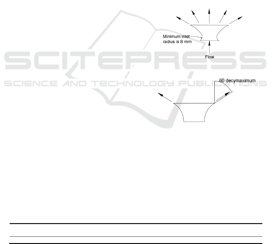
(3) Radius of rounded corners of the ventilation
pipe
The minimum fillet radius of the ventilation pipe
is 8mm, as shown in figure 2.
(4) Angle on both sides of ventilation pipe
The Angle on both sides of the ventilation pipe
should not exceed 60°, in order to reduce airflow
loss, as shown in figure 3.
Figure 2. Minimum rounded radius of ventilation pipe.
Figure 3. Angle of both sides of ventilation pipe.
(5) Left and right ventilation pipes
The left and right ventilation ducts are located at
the lower end of the outlet of the main ventilation
ducts. The diameter of the left and right ventilation
ducts is 27mm.
(6) Chamfering of ventilation pipe
When designing chamfering, the wall thickness
of the parts shall be uniform and uniform, and the
chamfering design shall be 3.2mm. The main size
data of ventilation pipe are shown in table 1.
Table 1. Main size data of ventilation pipe (unit: mm).
Outlet
width
Outlet length
Inlet width
Inlet length
Ventilation height
Ventilation pipe
thickness
25
600
75
400
80
2
ICVMEE 2019 - 5th International Conference on Vehicle, Mechanical and Electrical Engineering
56
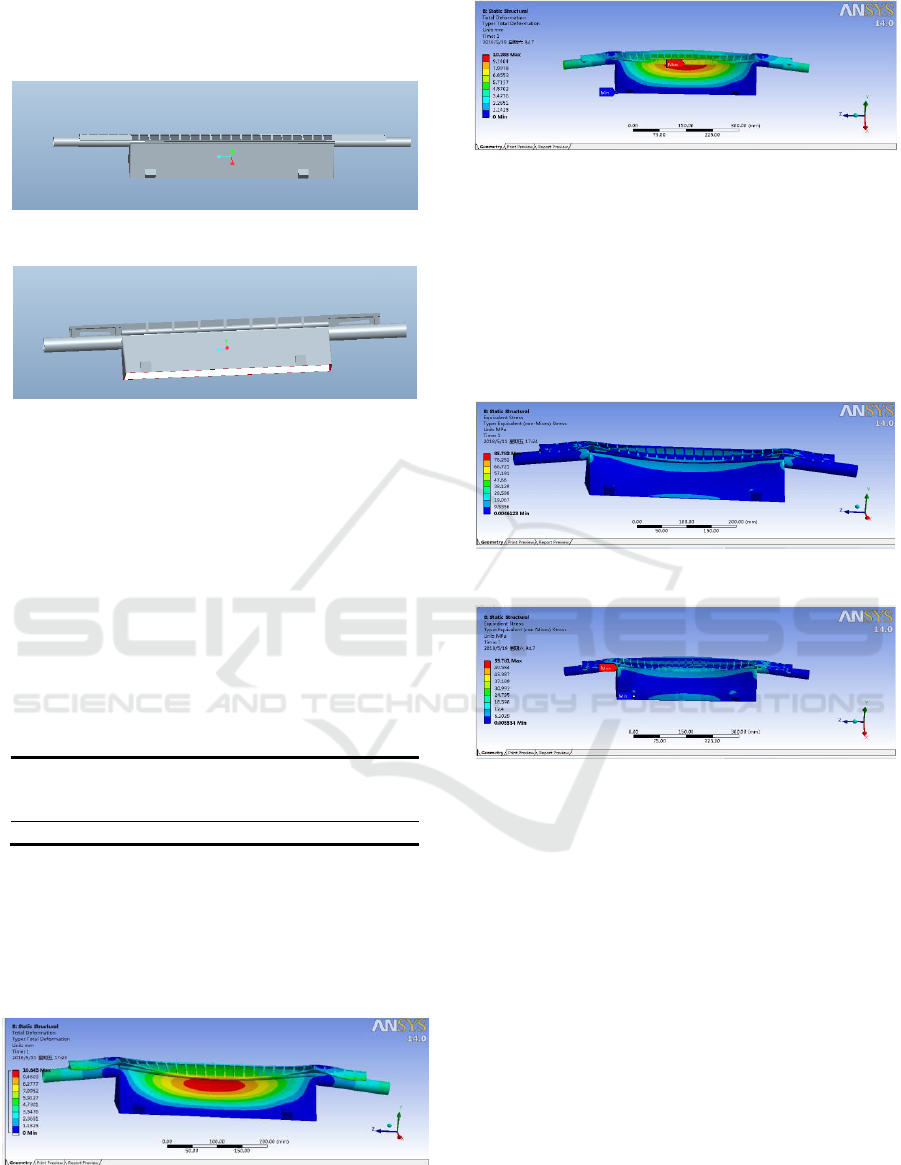
3d software Pro/E was used to establish the
model before and after improvement of the
ventilation pipe, as shown in FIG.4 and FIG. 5.
Figure 4. Before improvement of ventilation model.
Figure 5. Improved ventilation model.
4 COMPARATIVE ANALYSIS OF
FINITE ELEMENT
STRUCTURE BEFORE AND
AFTER VENTILATION PIPE
IMPROVEMENT
The material properties of the ventilation pipe finite
element model are shown in table 2.
Table 2. Ventilation pipe material properties.
elasticity
modulus
(N/mm2)
poisson
ratio
density
(kg/m
3
)
load
(N)
ultimate
strength
(MPa)
1300
0.39
910
1500
70
Reinforcing bars were added to the ventilation
pipe. Finite element analysis was carried out before
and after the ventilation pipe was improved by
ANSYS Workbench, and the deformation amount
and stress cloud diagram were obtained as shown in
figure 6, 7, 8 and 9 respectively.
Figure 6. Deformation of ventilation pipe before
improvement.
Figure 7. Deformation of ventilation pipe after
improvement.
By observing the deformation amount of
ventilation pipe in FIG. 6 and 7, it can be seen that
the maximum deformation amount of ventilation
pipe before improvement in FIG. 6 is 10.643mm.
The ventilation pipe was reinforced, and the
improved deformation was reduced from 10.643mm
to 10.283mm.
Figure 8. Before improvement of ventilation pipe stress.
Figure 9. Improved ventilation pipe stress.
By observing FIG. 8 and 9 strain diagram of
ventilation pipe, it can be seen that the maximum
stress value of the ventilation pipe before
improvement in FIG. 6 is 85.783mpa, which is
greater than the ultimate strength of 70MPa, and
fails to meet the requirements of ventilation pipe
strength. The maximum stress value of the
ventilation pipe after the reinforcement was added
was 55.781MPa, less than 70MPa, which met the
strength requirements of the ventilation pipe.
In summary, the deformation and stress values of
the ventilation pipe before and after improvement
are shown in table 3. It can be known from the table
that the maximum stress value of the ventilation pipe
before improvement is 85.783MPa, greater than the
ultimate strength of 70MPa, and the maximum stress
value of the ventilation pipe after improvement is
55.781MPa, less than the ultimate strength of
70MPa, meeting the strength requirements. The
Analysis and Research on Defrosting Ventilation Pipe Deformation of Automobile
57
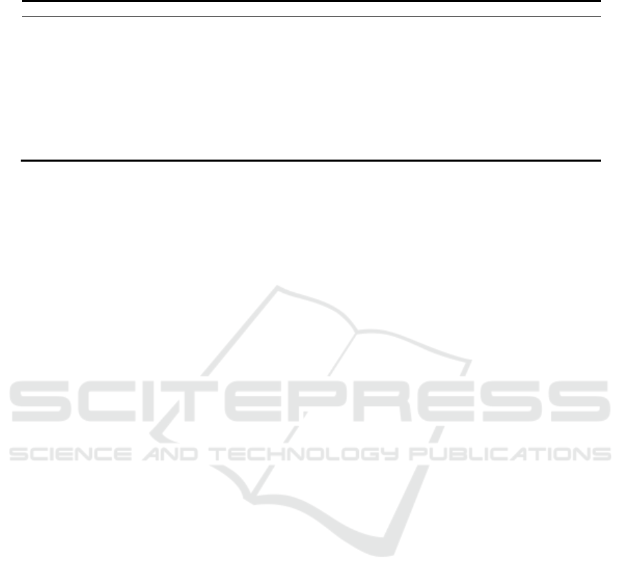
Table 3. Ventilation pipe material properties.
Load(N)
Deformation (mm)
Stress value(MPa)
before improvement
improved
before improvement
improved
1500
10.643
10.283
85.783
55.781
1500
9.4603
9.1404
76.252
49.584
1500
8.2777
7.9978
66.721
43.387
1500
7.0952
6.8553
57.191
37.189
1500
5.9127
5.7127
47.660
30.992
1500
4.7301
4.5702
38.129
24.795
1500
3.5476
3.4276
28.598
18.598
1500
2.3651
2.2851
19.067
12.400
1500
1.1825
1.1425
9.5356
6.2029
comparison of ventilation before and after
improvement shows that it is feasible to add
reinforcing bars to the ventilation pipe.
5 SUMMARY
This paper is mainly based on the automobile
defrosting ventilation pipe does not fit seriously
affect the automobile brand and driving safety, find
out the defrosting ventilation pipe position
deformation reason, according to the deformation
reason to put forward the improvement plan of
adding reinforcement on the back of the ventilation
pipe. By using Pro/E software on car ventilation tube
before and after improvement, 3 d modeling, using
ANSYS Workbench software model for finite
element analysis before and after improvement of
ventilation tubes, through the comparison and
analysis to verify the ventilation pipe add
reinforcement on the back of the rationality of the
improved scheme, the auto defrost ventilation pipe
has certain reference significance, optimal design to
improve design quality, reduce design cost and
shorten the development cycle, has good practical
significance.
ACKNOWLEDGMENTS
Fund projects: outstanding youth project of
education department of hunan province (16B235),
general scientific research project of education
department of hunan province (17C1444 and
16C1432), and CX2016SY015 of postgraduate
scientific research innovation project of shaoyang
university.
About the author: li guangming (1983-), male, born
in shaoyang, hunan province, master degree, mainly
engaged in vehicle engineering teaching and
research of automobile testing technology.
REFERENCES
Tang Zhiliang. Research on defusing performance of
automobile windshield frost fog [D]. Hunan
University, 2014.
Wangjiansong. Research on the Measurement and
Estimation of Gravity Vertical Line Deviation [D].
Southeast University, 2018.
Songke. Study on fatigue damage properties of PP
materials [D]. Kunming University of Technology,
2015.
ICVMEE 2019 - 5th International Conference on Vehicle, Mechanical and Electrical Engineering
58
