
Finite Element Model Establishment and Strength Analysis of Crane
Boom
Linyan Zhang
1
, Hongliang Zhang
1, a, *
,Changguo Lu
1
1
Department of Computing,Yingkou Institute of Technology, Yingkou,China
Keywords: Crane Boom, Finite element analysis, Strength Analysis.
Abstract: This paper is devoted to the strength analysis of crane boom with Ansys software. The results of strength
analysis and theoretical calculation are compared and analyzed, and a method of using software to analyze
the strength of crane boom is discussed. Firstly, using SolidWorks software, the three-dimensional model of
each jib of the main arm of heavy crane is established by means of shell pulling, which is saved in x-t
format. Secondly, the three-dimensional model is imported into Ansys software, and the finite element
model of heavy crane boom is established by assigning attributes and meshing. Thirdly, the crane boom
priority model is constrained and loaded, and the static simulation is carried out. Finally, the simulation
results and theoretical results are compared and analyzed to verify the accuracy of the model (SINGH B,
et.al, 2011; TOMASZ G, et.al, 2011).
1 ESTABLISHMENT OF FINITE
ELEMENT MODEL OF CRANE
BOOM
1.1 Applying SolidWorks Software to
Build Three-Dimensional Model
Firstly, the three-dimensional model of crane boom
is established by using SolidWorks software. In
SolidWorks, all boards extract the middle surface,
and all tubes extract the axis to build a three-
dimensional model. The model of the crane boom
needs to be established, including the boom root, the
boom head, the completed 3m, 6m, 12m middle
boom. According to the requirement of the subject,
the structure size of the arm frame of the main arm is
determined. According to the size requirement, the
arm head and the arm root of the main arm are
drawn. The model is shown in Figures 1 and 2.
Fig 1. Arm Root.
Fig 2. Arm Head.
1.2 Introduction to Ansys Software
Ansys software is developed by American Ansys
Company. It is a finite element analysis software
which integrates structure, fluid, electric field,
magnetic field, sound field and thermal analysis. It
has corresponding interfaces with most software
(such as Pro/Engineer, Hypermesh, Adams, Nastran,
Ideas, etc.), and can realize data sharing and
exchange between them. The cell types used in this
paper are shell 63 unit, beam 188 unit, link 180 unit
and mass 21 unit.
1.3 A Simplified Scheme for Modeling
Process Using Ansys Software
Beam 188 beam element is commonly used in Ansys
to simulate the main chord and web members. This
element can define the cross-section shape and also
simulate the mechanics of the main chord and web
192
Zhang, L., Zhang, H. and Lu, C.
Finite Element Model Establishment and Strength Analysis of Crane Boom.
DOI: 10.5220/0008850001920196
In Proceedings of 5th International Conference on Vehicle, Mechanical and Electrical Engineering (ICVMEE 2019), pages 192-196
ISBN: 978-989-758-412-1
Copyright
c
2020 by SCITEPRESS – Science and Technology Publications, Lda. All rights reserved
members. The shell 63 element is used to simulate
the plate of the arm head in the boom. The shell 63
element is commonly used in Ansys software. It is
convenient to use. For other pull plates, it is
simulated by link8 element, which is a three-
dimensional bar element and is a tension and
compression element in the direction of bar axis.
Beam 188 beam element model is used to analyze
the chord and web members.
1.4 The Finite Element Model of Heavy
Crane Boom Is Established By
Using Ansys Software
In SolidWorks, all the boards are extracted from the
middle surface, and all the tube axes are extracted to
build a three-dimensional model, which is saved in
x-t format and imported into Ansys for modeling. In
Ansys, shell 63 unit is used for board, beam 188 unit
is used for tube, mass21 unit is used for key point
and link 180 unit is used for pulling board.
In Ansysysy, the solid models established from
Solidworks are imported to define their material
properties, the real constants are given to the plates
according to the thickness of the plates, and the
cross-section properties of the tubes are defined
according to the diameter and thickness of the tubes.
Finite element mesh analysis is carried out on them,
and mesh errors are checked and modified, and finite
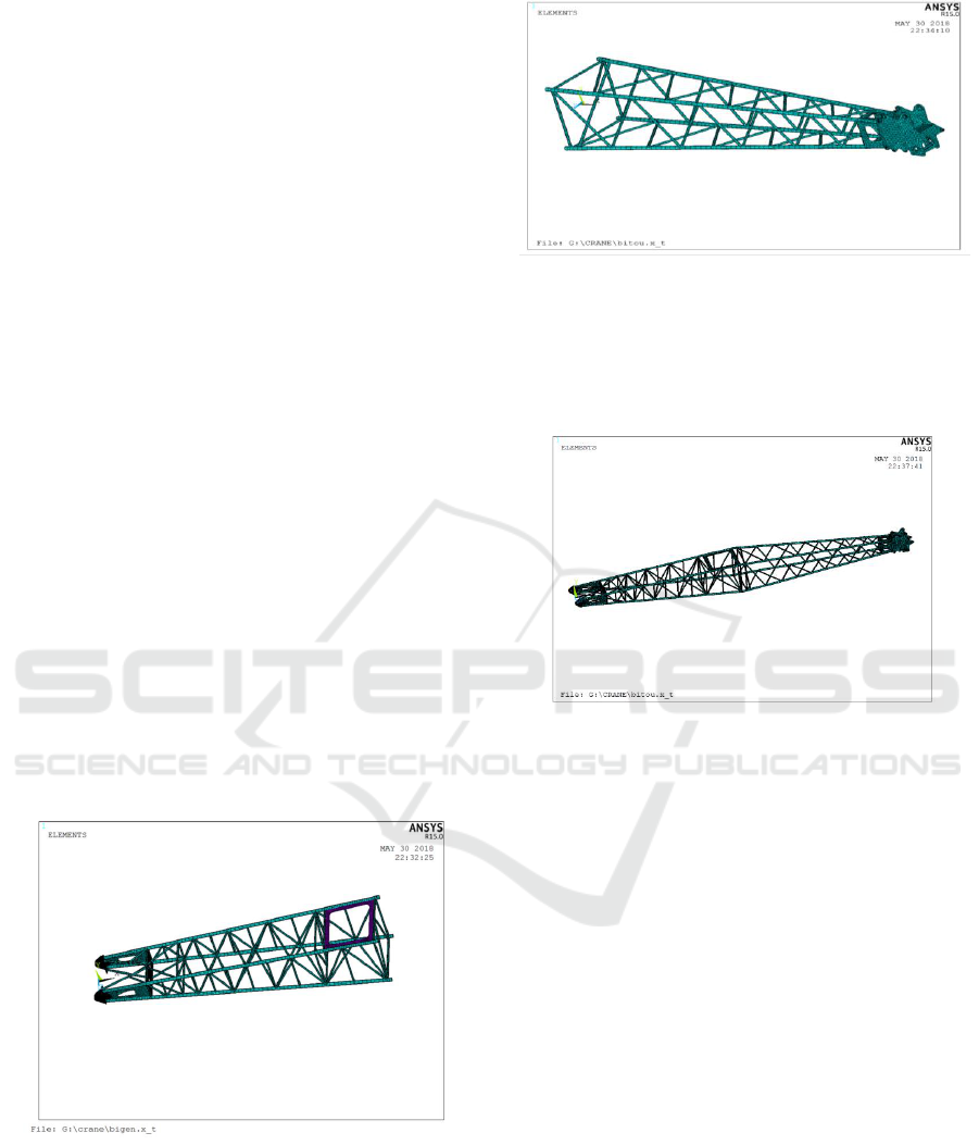
element models are established. Fig. 3 is the arm
root finite element model, and Fig. 4 is the arm head
finite element model.
Fig 3. Arm Root Finite Element Model.
Fig 4. Finite Element Model of Arm Head.
The arm is connected with the arm root by
moving, writing out and reading operation. The
finite element model of the 13m basic main arm is
established, as shown in Fig. 5.
Fig 5. Finite element model of 13m main arm.
2 STRENGTH ANALYSIS OF
CRANE BOOM
As shown in Figure 6, the basic main arm of 13m is
adjusted to the working state of minimum radius and
maximum hoisting by moving and rotating.
According to the position of the lower hinge point of
the pulling plate in the working condition, the key
points are established and the connecting arms are
separately. For the two pulling plates, the link188
element can only be divided into one cell. The upper
end of the drawing plate and the hole are connected
by rigid area.
Finite Element Model Establishment and Strength Analysis of Crane Boom
193
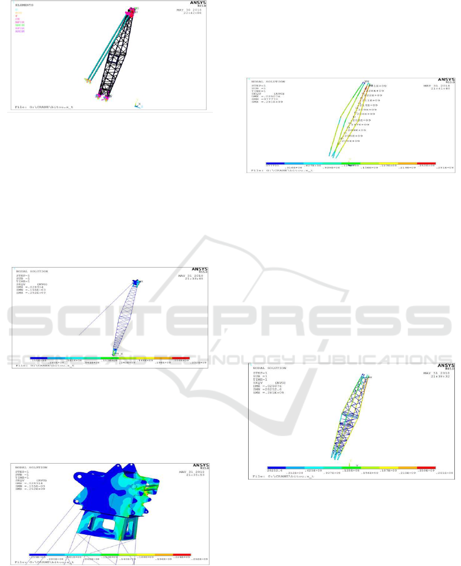
Fig 6. Force model of 13m main arm.
In the articulated position of the lower arm root
and the articulated position of the upper arm head,
the rigid region is established by mass21, and the
rigid region is also established in the contact
position of the tube and the plate. In the articulated
position of the lower end of the arm root, the
constraints of ux, uy and UZ displacement directions
are added, and the lower end of the pull plate is fully
constrained. Add 539 KN downward force to the
arm lifting position, and add to the whole system.
Fig 7. Total stress nephogram of 13m main arm.
From the total stress nephogram of the main arm,
it can be seen that the maximum displacement of the
main arm is 28.314 mm, the maximum stress is 252
MPa, and the position of the main arm appears in the
arm head. See Fig. 7 for details.
Fig 8. Maximum stress nephogram of Figure 8.
From Figure 8, it can be seen that the maximum
stress position of the slab is in contact with the
lifting load, and the stress near the slab is relatively
large, averaging about 135 MPa. Q235 is adopted in
this design, and its allowable stress is 213MPa,
which is larger than the result of finite element
calculation and meets the strength requirement. For
the position where the maximum stress occurs due to
the smaller chamfer, there is the possibility of stress
concentration, so we can try to improve the design.
Fig 9. Maximum stress nephogram of Q345 main chord.
From the stress nephogram of the main chord, it
can be seen that the maximum position of the actual
stress appears on the lower main chord with the
upper arm, and its maximum stress value is 281 MPa.
The stress of the lower main chord is larger than that
of the upper one, which accords with the fact that the
upper main chord is under tension and the lower
main chord is under compression. The maximum
stress distribution of the lower main chord is about
220 MPa on average. The allowable stress of Q345
is 313 MPa, which is larger than the result of finite
element calculation and meets the strength
requirement.
Fig 10. Stress nephogram of pipe.
Fig. 10 is the stress nephogram of the pipe. The
maximum stress appears at the end of the arm. The
material chosen is Q345. The maximum stress value
is 281 MPa, which is greater than 213 MPa. Its
strength meets the requirements.
ICVMEE 2019 - 5th International Conference on Vehicle, Mechanical and Electrical Engineering
194

Fig 11. Nephogram of Abdominal Canal Force.
Figure 11 shows that the maximum stress of the
abdominal canal occurs at the upper arm, followed
by the root of the arm. The material used is Q235
and its allowable stress value is 109 MPa, which is
larger than the result of finite element calculation
and meets the strength requirement.
3 COMPARISON OF
THEORETICAL
CALCULATION AND
SOFTWARE ANALYSIS
RESULTS OF BOOM
STRUCTURE STRENGTH
According to the theoretical calculation of plate
strength and the strength analysis by ANSYS
software, the results are compared. In the analysis
results of Ansys software, the blue part accounts for
most of the area, and the red part is the largest part
of the plate. As shown in Fig. 12, when the
dangerous section is 10 m away from the root of the
boom:
Figure 12. Hazardous Section Analysis C.
=
=839.4/4×2093=100.26MPa (1)
Q
-
Fg
=490×1.1×
-
218.21×3×
280.8
-
225.8=55KN.m (2)
So
=
()
=55×
/3.67×
=150MPa (3)
Therefore, the stress of the upper and lower main
chord is zero:
=
-
=150 MPa
-
100.26MPa=49.74MPa (4)
=
+
=150 MPa+100.26MPa=250.26MPa(5)
The stress of the main chord is 49.74 MPa on the
dangerous section, which is 10 m away from the arm
root of the boom. The stress of the lower main chord
is 250.26 MPa. The result of Ansys software
analysis is 242 MPa. The error is about 3.30%.
The theoretical calculation value regards the
whole boom as a homogeneous rigid body, and
simplifies the position of the pulling plate and the
lifting load to the same point, which is different
from the actual value and is not particularly accurate.
Therefore, the theoretical calculation value and the
results of finite element analysis have errors, but the
error is within 5%. The finite element model and the
calculation results can be basically considered.
Correct.
4 CONCLUSION
In this paper, the three-dimensional model of crane
boom is established by Solidworks software, and the
finite element model of crane boom is established by
introducing Ansys software. The strength analysis of
crane boom is carried out by using finite element
model. Finally, the strength analysis results of
application software and theoretical calculation are
compared. The accuracy of strength analysis results
is verified. The research results of this paper have
strong practical and theoretical significance for the
application of crane boom strength analysis in
engineering.
Finite Element Model Establishment and Strength Analysis of Crane Boom
195

REFERENCES
KUMA N, PARVEZ M. Force distribution on telescopic
boom of Crane [J].International Journal of Mechanical
Engineering and Robotics Research, 2012, 1(2):97-104.
SINGH B, NAGAR B, KADAM B S, et al. Modeling and
finite element analysis of crane boom [J]. International
Journal ofAdvanced Engineering Research and Studies,
2011, 1(1): 51-55.
TOMASZ G, WOJCIECH S. Modeling and research into
the vibrations of truck crane [J]. Scientific Research of
the Institute of Mathematics and Computer Science,
2011, 1(10): 49-60.
ICVMEE 2019 - 5th International Conference on Vehicle, Mechanical and Electrical Engineering
196
