
A Kinematic Design of 3-PRS Precision Compliant Parallel Platform
Zhiping Kong
1, 2, a
, Wei Zhang
1, 2, b
, Haibo Zhou
1, 2, c
1
School of Mechanical and Electrical Engineering, Central South University, Changsha, China
2
State Key Laboratory of High Performance Complex Manufacturing, Central South University, Changsha, China
Keywords: Parallel platform, Kinematics analysis, Large-stroke flexure joints.
Abstract: A kinematic design of the 3-PRS compliant parallel platform with wide-range flexure hinges is presented in
this paper. The manipulator is driven by the piezoelectric motors, which can show the superiority of parallel
platforms and large-stroke flexure hinges. First, taken into account the parasitic motions of the platform, the
kinematics solution is proposed. Then, the influence of parameters to the rotation capacity and relative
rotation error that are used to assess the quality of the revolute and spherical flexure joints. Also, the
reachable travel is observed by ANSYS Workbench. Finally, compare with the FEM and the theoretical
results by several different cases to ensure the efficiency of the kinematics model.
1 INTRODUCTION
High-precision positioning devices are often
required in different areas as scientific, medical and
communication fields for micro-system production
(Ruiz, et al., 2016). For these high-tech applications,
it is necessary to overcome the problems they
usually appear, as clearances, friction and wear,
which greatly affect the accuracy of the platform (Li
and Xu, 2007). A well-known solution for these
problems was put forward in (Bhagat U, et al., 2014),
which introduced the compliant machines with the
flexible hinges to improve the motion accuracy.
Parallel machine were first applied in the test of
tire by Gough, and later were introduced by Stewart
as the simulators (Stewart and D, 1965). Then the
Stewart structure began to be widely used in many
fields. Parallel manipulators with 6-DOF have many
advantages. Dong et al established a kinematics
model via analysing the stiffness model of the whole
6-PSS platform based on FEA method (Dong, et al.,
2005). Recently, parallel platforms with less than 6-
DOF have appeared in many different fields.
Rouhani et al developed a method on the basis of
elastokinematic analysis of a microhexapod
manipulator, in which the elastic deformation of the
flexure hinges was considered for the kinematic
analysis (Rouhani, et al., 2016). Meanwhile, It is
possible to develop 2-DOF mechanisms, as for
example the stage presented in (Huang and Dao
2016), where the stage with flexure elements allows
large displacement along x and y direction. Also, the
paper provides some useful steps for designing and
analyse by FEM. Many 3-DOF parallel manipulators
also have been designed and applied for relevant
areas. For example, the 3-UPU parallel robots with
pure translational motions in (Gregorio, et al., 1998),
other sample of this type is shown in (Liu, et al.,
2005), where the parallel manipulator HANA has
three DOF with one rotational and two translational
degree of freedom. Another 3-DOF mechanism is
presented in (Li,et al., 2005; Zhan, et al., 2005),
where the kinematic of the 3-RPS parallel
mechanism is analysed. Moreover, the necessary
steps to achieve a good design and characterization
are presented. Also 3-PUU mechanism with 2R1T is
proposed in (Wang, et al., 2016), where the mobility
analysis of the platform is carried out by the
reciprocal screw theory.
The 3-PRS parallel platforms were widely
designed and analysed in (Ruiz, et al., 2016; Li and
Xu, 2007; Jia, et al., 2016; Li, et al., 2016; Tsai, et
al., 2003). The 3-PRS parallel platform with large-
stroke flexure joints introduced in this paper. At
present, it is still a challenging task to solve the
design and kinematic problem with flexible joints.
For the mechanisms with flexible joints, they can
overcome many problems, but they also faced some
challenge, like the deformation of the joints and the
parasitic motions. Therefore, it is necessary to study
the design, kinematics and validate these compliant
parallel platform with flexible joints.
Kong, Z., Zhang, W. and Zhou, H.
A Kinematic Design of 3-PRS Precision Compliant Parallel Platform.
DOI: 10.5220/0008849403410346
In Proceedings of 5th International Conference on Vehicle, Mechanical and Electrical Engineering (ICVMEE 2019), pages 341-346
ISBN: 978-989-758-412-1
Copyright
c
2020 by SCITEPRESS – Science and Technology Publications, Lda. All rights reserved
341
The present will develop the conceptual design,
kinematics study, FEM validation of the 3- PRS
parallel mechanism. Firstly, the design of the 3-PRS
parallel platform are presented in Section 2. Then
the kinematics are analysed in Sections 3, where the
rigid body kinematics of the 3-PRS will be
developed. The FEM of the large-stroke joints will
be explained in section 4, where the kinematics
simulation are concluded. Finally, some concluding
remarks are given in Section 5.
2 SYSTEM DESCRIPTION
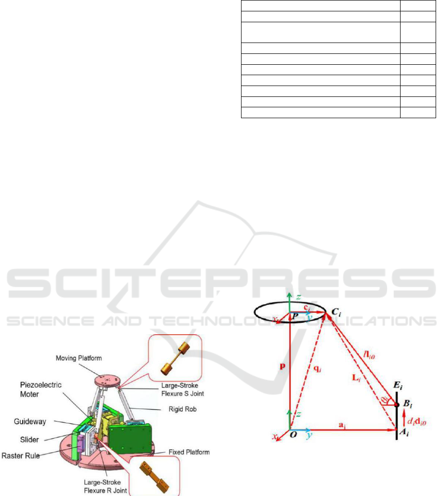
The structure of a 3-PRS parallel manipulator is
composed of a moving platform, a fixed base, and
three identical supporting limbs, which is shown in
Figure 1. Each kinematic limb consists of two wide-
range flexure hinges and a rigid rod in the middle.
As shown in Fig.1, one wide-range flexure hinges is
spherical joint (S) that can rotate around three axes,
another is revolute joint (R) that can rotate around
one axe. They can not only have high accuracy, but
also achieve a long strike motion for parallel
platform. The driving components as active joint (P),
and a piezoelectric motor is utilized as actuator,
which has many advantages as high precision, high
driving force and large travel. Here, beryllium
bronze and duralumin are used as the material of the
long-stroke flexible joints and the others.
Figure 1. Basic configuration of the 3-PRS parallel
manipulator.
The main parameters of the platform are
obtained, as shown in Table1.
Table 1. The structure parameters of the 3-PRS parallel
manipulator.
Item
Value
Diameter of moving platform
50mm
Angle between the kinematic chain and
the fixed platform
65°
Length of rigid rod
76mm
Diameter of rigid rod
10mm
chamfering radius of S joint and R joint
1mm
Diameter of S joint
1mm
Length of S joint and R joint
12mm
Thickness of R joint
0.4mm
Width of R joint
8mm
3 KINEMATICS ANALYSIS
The structure of the 3-PRS parallel mechanism is
shown in Figure 2. Three coordinate systems are
considered: the local coordinate systems P(xyz) in
the center of the moving platform; and the global
coordinate systems O(xyz) in the center of the fixed
platform. The position of the center of the moving
platform can be expressed by px , py and pz, and its
direction can be represented by the angles α, β, and γ,
which are the rotation angle around the x, y and z
axes, respectively..
Figure 2. One limb of structure with coordinate systems of
the platform.
Therefore, the displacement vector of the center
of the moving platform in the moving frame P can
be expressed as:
T
p x y z
d p p p
(1)
Also, the position vectors of the S joints Ci (i=1,
2, 3) in P(xyz) frame can be defined by:
ICVMEE 2019 - 5th International Conference on Vehicle, Mechanical and Electrical Engineering
342
T
1
T
2
T
3
[ 0 0]
[ / 2 3/2 0]
[ / 2 - 3/2 0]
PC r
PC r r
PC r r
(2)
Then, it is possible to obtain the rotation matrix
T from the moving frame P(xyz) to the reference
frame O(xyz), which can be expressed as:
x y z
x x x
y y y
z z z
T R R R
u v w
u v w
u v w
(3)
The position vectors Ci (i=1,2,3) in the reference
frame O can be defined by:
ii
OC OP T PC
(4)
Substituting Eq.(2) and Eq.(3) into Eq.(4), we
can obtain:
1
2 1 1 2 2 3 3
3 1 1 2 2 3 3
[ ]
[ ]
[ ]
T
x x y y z z
T
x y z
T
x y z
OC p u r p u r p u r
OC p u v p u v p u v
OC p u v p u v p u v
(5)
Where
2
1
ru
u
x
,
2
2
ru
u
y
,
2
1
ru
u
z
,
2
3
1
ru
v
x
,
2
3
2
ru
v
y
,
2
3
3
ru
v
z
.
The position vectors of the R joints
( 1,2,3)
i
Bi
in O frame can be expressed as:
T
11
T
22
T
33
[ 0 ]
[ / 2 3/2 ]
[ / 2 - 3/2 ]
OB R d
OB R R d
OB R R d
(6)
Where
3,2,1id
i
represented the translation
of the passive joint.
Substituting Eq.(5) into Eq.(6) yields, the
parasitic motions can be obtained:
s s
-atan
cc
(7)
c c s s s -c c
2
x
r
p
(8)
c s c s s
2
y
r
p
(9)
From the Figure 2, we can know the relation:
iiiii
OBOCBCL
(10)
Where
i
OC
and
i
OB
are expressed in Eq.(5) and
Eq.(6).
Since
3,2,1id
i
is the only unknown variable
in Eq.(6), solving Eq.(10) allows us to obtain the
solutions for the inverse kinematic problem.
2
2
2
i iz ix ix iy iy
d OC l OB OC OB OC
(11)
4 SIMULATION RESULTS
4.1 Simulation Design of the Large-
Stroke Flexure Joints
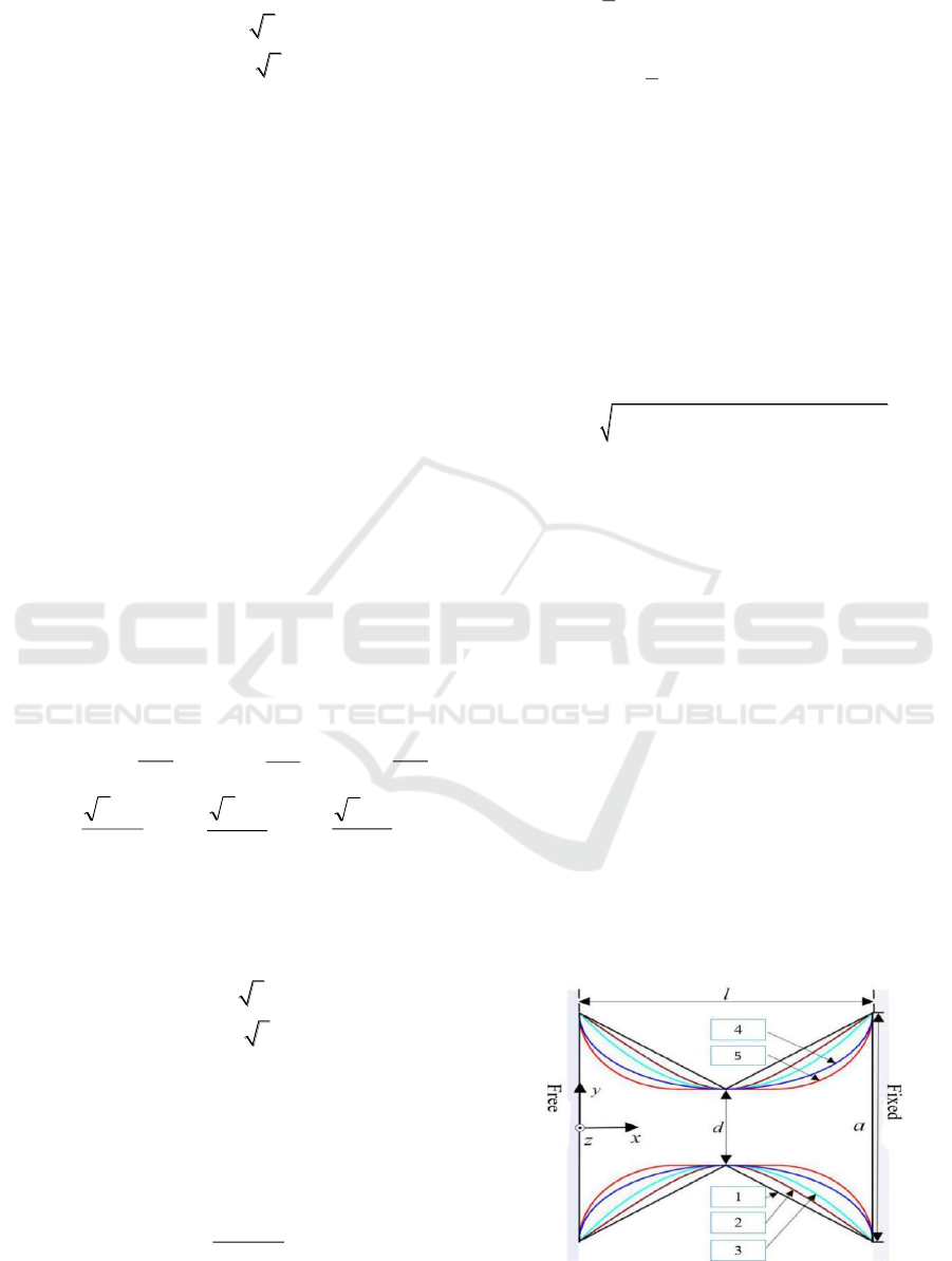
There are many types of flexible hinges. There are
five common types: V-shaped, hyperbolic, parabolic,
elliptical, and rounded straight beam flexible hinges,
which correspond to 1~5 in Figure 3 below. For the
same material, the same boundary and load
conditions of 5N, the deformation and stress of the
flexible hinges by ANSYS workbench were shown
in Figure 4. The maximum displacement is in the
order of: 5 > 4 > 3> 2> 1. The larger the maximum
displacement of the flexible hinge, the more helpful
it is to meet the large stroke requirement of the
motion platform. By comparison, a rounded straight
beam type flexible hinge has better structural
characteristics and mechanical properties.
Figure 3. The section type of the flexible hinge.
A Kinematic Design of 3-PRS Precision Compliant Parallel Platform
343
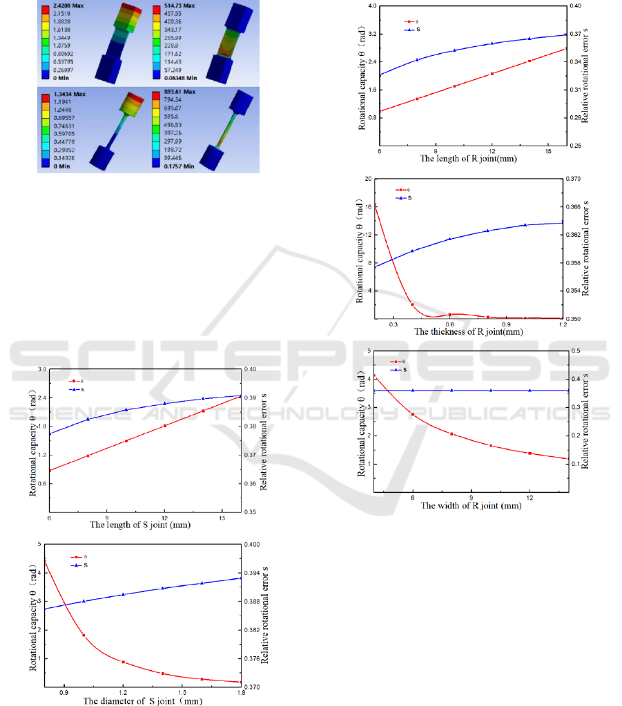
A theoretical mechanical model is established for
the flexible hinge, and the evaluation indexes
includes rotational capacity θ and relative rotational
error s, which can be seen in (Shi, et al., 2013).
Figure 4. The deformation and stress of the flexible hinges.
It can be seen that the main parameters affecting
the performance of the flexible spherical joint are:
the length of the hinge deformation part L and the
minimum diameter of the middle elongation t. A
group of typical values L=12mm, t=1mm are
selected, then change a variable near the typical
value with other variables fixed , the data graphs of
the influence on rotational capacity and relative
rotational error are shown in Figure 5.
Figure 5. The performance of the flexible spherical joints
in terms of L and t.
In the same way, the main parameters affecting
the performance of the flexible revolute joint are the
length L, the minimum thickness t, and the width b.
A group of typical values L=12mm, t=0.4mm, and
b=8mm were selected, and the data graphs of
influence are shown in Fig 6.
Figure 6. The performance of the flexible rotating joints in
terms of L, t and b.
As shown in Figure 5 and Figure 6, with the
increase of the length of the joints, the rotational
capacity and the relative rotational error increased.
The increase in the diameter of S joints, the
thickness and width or R joints causes the increased
rotational capacity and the educed relative rotational
error. At the same time, the influence of the hinge
size on the stiffness and stroke of the platform is
also analyzed. The influence on the stroke of the
platform and the law of the hinge size and the
rotation ability are the same. By contrast, the
influence on the stiffness of the platform is opposite
to the rotation ability.
ICVMEE 2019 - 5th International Conference on Vehicle, Mechanical and Electrical Engineering
344
4.2 Inverse Kinematics Simulation
As shown in Table 2, the five pose values of the
given platform are input into the pseudo rigid body
kinematics model and the FEM model respectively
to obtain the displacement of the driver. It can be
seen from the above table that the results of Matlab
and Ansys calculations are very small, the error is
within 2%, which verifies the correctness of the
kinematics model, and also shows that the flexible
parallel motion platform is regarded as a rigid body
under small deformation conditions. The feasibility
of the analysis. And the motion range of the moving
platform are in Table 3.
Table 2. Comparison of FEA and Theoretical analysis.
z,α,β
(mm,°,°)
Theoretical
d1,d2,d3
(mm,mm,mm)
FEM
d1,d2,d3
(mm,mm,mm)
(5,0,0)
(5,5,5)
(5,5,5)
(0,0,0.5)
(-0.2373,0.1193,
0.1193)
(-0.2385,0.1208,
0.1207)
(0,0.5,0)
(-0.0001,0.2070,
-0.2056)
(0.0005,0.2091,
-0.2066)
(0,1,0.5)
(-0.2383,0.5355,
-0.2931)
(-0.2367,0.5425,
-0.2912)
(0.5,0.5,1)
(0.0264,0.9447,
0.5309)
(0.0262,0.9532,
0.5344)
Table 3. The motion range of the moving platform.
Positive
limit
Negative
limit
Angular displacement
around x axes(°)
9.2
-9.3
Angular displacement
around y axes(°)
9
-9.5
Linear displacement
along z axes(mm)
10
-10
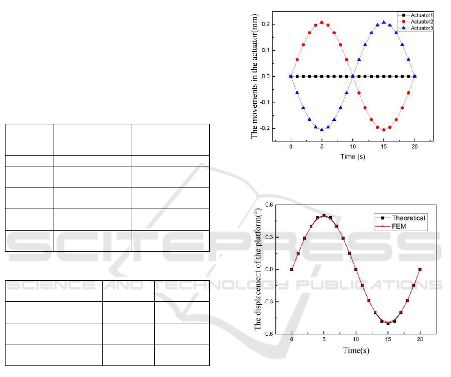
4.3 Forward Kinematic Simulation
Given a trajectory of the platform,
)2sin(5.0 t
,
calculate the movements of the driving units by the
FEA model and the inverse kinematic model. Then
the values were employed to the forward kinematic
model by FEA respectively. The movements in the
actuator are shown in Figure 7, and the trajectory of
the platform by theoretical modal and FEA modal
are shown in Figure 8. The comparison between two
models shows that the maximum positioning error is
0.0075 degrees in the range of 0.5 degrees. The
results shows that the errors between two models are
very small.
5 CONCLUSION
In this paper, a new 3-PRS compliant micro parallel
platform with large-stroke hinges is presented. The
platform is driven by a piezoelectric motor, and the
Figure 7. The movements of the actuators.
Figure 8. The end pose of the platform.
wide-range flexure hinges including spherical hinges
and rotating hinges, which can improve the accuracy
and increase travel. The FEA model of the large-
stroke hinges are developed to analyze the
characteristics and mechanical properties.
Meanwhile, by using of the ANSYS Workbench,
obtain the workspace of the manipulator, which can
reach about 18° around x axes, 18° around y axes,
more than 20mm along z axes depending on the
travel of the drive part. An inverse kinematic
solution is given, several comparison results
between theoretical and simulation show that the
model is effective for modeling compliant parallel
platforms with wide-range flexible joints.
A Kinematic Design of 3-PRS Precision Compliant Parallel Platform
345

ACKNOWLEDGMENTS
This work was supported in part by the National Key
Research and Development Program of China under
Grant 2017YFB1104800, in part by the National
Natural Science Foundation of China under Grant
51575534.
REFERENCES
Bhagat U, Shirinzadeh B, Clark L, et al. (2014). Design
and analysis of a novel flexure-based 3-DOF
mechanism. Mechanism & Machine Theory,
74(6):173-187.
Dong, W. Du, Z, and Sun, L. (2005). Stiffness influence
atlases of a novel flexure hinge-based parallel
mechanism with large workspace. IEEE/RSJ
International Conference on Intelligent Robots &
Systems. IEEE. Pages 856-861.
Gregorio, R. D., and Parenti-Castelli, V. (1998). A
translational 3-DOF parallel manipulator. Advances in
Robot Kinematics: Analysis and Control, Page 49–58.
Huang, S. C, and Dao, T. P. (2016). Design and
computational optimization of a flexure-based xy
positioning platform using fea-based response surface
methodology. International Journal of Precision
Engineering and Manufacturing, 17(8):1035-1048.
Jia, D. Y, Zhang, J. M., Niu, Z. G. et al. (2007). Inverse
kinematics analysis and numerical control experiment
for PRS-XY style hybrid machining tool. Frontiers of
Mechanical Engineering, 2(2):235-238.
Li, Q. Chen, Z. Chen, Q. Wu, C. and Hu, X. (2011).
Parasitic motion comparison of 3-PRS parallel
mechanism with different limb arrangements.
Robotics and Computer-Integrated Manufacturing,
27(2):389-396.
Liu, X. J, Tang, X., and Wang, J. (2005). Hana: a novel
spatial parallel manipulator with one rotational and
two translational degrees of freedom. Robotica,
23(2):257–70.
Li X, Zhu D, Mei Z, et al. (2017). Kinematic analysis of 3-
RPS parallel mechanism.International Conference on
Robotics and Automation Engineering. 2017:183-187.
Li, Y, and Xu, Q. (2007). Kinematic analysis of a 3-PRS
parallel manipulator. Robotics and Computer-
Integrated Manufacturing, 23(4):395-408.
Rouhani, E., and Nategh, M. J. (2016). An elastokinematic
solution to the inverse kinematics of microhexapod
manipulator with flexure joints of varying rotation
center. Mechanism and Machine Theory, 97:127-140.
Ruiz, A, F. J. Campa, C. Roldán-Paraponiaris, Altuzarra,
O, and Pinto, C. (2016). Experimental validation of
the kinematic design of 3-PRS compliant parallel
mechanisms. Mechatronics, 39:77-88.
Shi, R. C, Dong, W. and Du, Z. J. (2013). Design
methodology and performance analysis of application-
oriented flexure hinges. Review of Scientific
Instruments, 84(7):065106.
Stewart, and D. (1965). A platform with six degrees of
freedom. ARCHIVE: Proceedings of the Institution of
Mechanical Engineers 1847-1982 (vols 1-196),
180(1965):371-386.
Tsai, M. S. Shiau, T. Tsai, Y. and Chang, T. (2003). Direct
kinematic analysis of a 3-PRS parallel mechanism.
Mechanism & Machine Theory, 38(1):71-83.
Wang, L. P, Xu, H. Y, et al. (2016). A novel 3-PUU
parallel mechanism and its kinematic issues. Robotics
and Computer-Integrated Manufacturing, 42:86-102.
Zhan, T. S, and Kao, C. C. (2010). Modified PSO method
for robust control of 3RPS parallel manipulators.
Mathematical Problems in Engineering, 2010(1):242-
256.
ICVMEE 2019 - 5th International Conference on Vehicle, Mechanical and Electrical Engineering
346
