
Nonlinear Coupled Dynamic Characteristics and the Stability of
Rotor-Bearing System under Rub-Impact and Oil-Film Forces
Miao Jin
1, 2, a
, Ailun Wang
1, 2, b
, Longkai Wang
1, 2
, Qike Huang
1, 2
1
College of Mechanical &Electrical Engineering, Central South University, Changsha 410083, China, Hunan Province,
China
2
State Key Laboratory of High Performance Complex Manufacturing, Central South University, Changsha 410083, PR
China
Keywords: Rotor-bearing system, Nonlinear oil force, Rub-impact, Jump phenomenon, Stability.
Abstract: The nonlinear coupled dynamic model of a rotor-bearing system with interaction between the rub-impact
and oil-film forces is established by the Lagrangian’s equation and D'Alembert principle. The nonlinear
coupled dynamic equation of rotor-bearing system with rub-impact and oil film force is investigated by the
4th-order Runge-Kutta method. Base on the dynamic model of rotor-bearing system, through Time domain
response, shaft trajectory, phase plane and amplitude spectrum are proposed to illustrate the nonlinear
coupled dynamic behaviors. then the largest Lyapunov exponent, Poincare map are identified to the
stability of the obtained computational data. The excitation frequency, stator stiffness and mass eccentricity
as the control parameters to study the influence of rotor-bearing system dynamics. Various nonlinear
dynamic characteristics are discovered in the rotor-bearing system, such as periodic-1, multi-periodic, quasi-
periodic and chaos motion are observed through the numerical simulation in this study. The numerical
results indicated that coupled effects of rub-impact and nonlinear oil film force have a great influence on the
vibration and instability of the rotor-bearing system as the varied excitation frequency. The nonlinear oil
film force causes the oil whirl in the rotor-bearing system at the low excitation frequency. The rub-impact
force mainly affects the dynamic characteristics of the high excitation frequency. The instability of rotor-
bearing system occurs in the critical speed due to the instability of oil film. Larger stator stiffness can
simplify the nonlinear dynamic response of system. As the stiffness of the stator increases, the system
response gradually transforms from chaotic motion to period-1 motion. Under the effect of a large
imbalance, jump phenomenon of system will be more obvious. and instability of system will occur in
advance. The corresponding results obtained in this paper may promote to the further understanding of
nonlinear dynamic behaviors of a rotor-bearing system and provide useful reference for suppressing the
fault of rotating machinery.
1 INTRODUCTION
Rotating machinery, one of the most significant
heavy machinery, are widely used mechanical
equipment in the industrial fields( Y. Zhang and W.
M.Wang, 2010). For example, such as aircraft
engine, gas turbine and steam turbine are all belong
to this category. As the core component of the aero-
engine, the rotor-bearing system are widely used in
the rotating machinery. Under the extreme
condition, such as oil film force, rub-impact force,
sealing force, pedestal looseness and initial bend are
all belong to the multiple nonlinear exciting sources.
These coupled faults can lead the rotor-bearing
system to be self-excited vibration and cause the
serious accidents. According to incomplete statistics
(W. Li, 2002), Engine fault caused by vibration
problems has accounted for 70% of total accidents.
In these accidents, the fault of rotor-bearing system
takes accounts for 60%-70% in the vibration fault.
According to relevant reports, due to the rub-impact
fault caused by engine turbine seals, four F-16
fighter jets were crashed in the United States in
1994-1995, forcing 339 flight to ground directly or
indirectly( D.-y. Wang, 1998).
Due to the demand for the high rotating speed
and improve the efficiency in the heavy-duty
rotating machines. It is common to decrease the
Jin, M., Wang, A., Wang, L. and Huang, Q.
Nonlinear Coupled Dynamic Characteristics and the Stability of Rotor-Bearing System under Rub-Impact and Oil-Film Forces.
DOI: 10.5220/0008849101750186
In Proceedings of 5th International Conference on Vehicle, Mechanical and Electrical Engineering (ICVMEE 2019), pages 175-186
ISBN: 978-989-758-412-1
Copyright
c
2020 by SCITEPRESS – Science and Technology Publications, Lda. All rights reserved
175

radial clearance between the rotor and stator when
designing a rotor-bearing system. A larger radial
clearance can result the possibility of the rub-impact
occurs as the excitation frequency increases.
Consequently, rub-impact fault is one of main
problem in the rotating machineries. the serious rub-
impact fault may cause the vibration accidents of
whole machine, blade break, Engine structure
damage and the instability of rotor-bearing system.
According to related reports, In the 1962, the second
prototype of the Harrier Jet (p.1127) was in the test
flight, due to rub-impact caused by the engine
compressor rotor blades-casing, eventually resulted
in the titanium alloy of engine to catch fire, the plane
crashed on a hillside.
The traditional dynamic characteristics of rotor-
bearing system mainly adopts the theoretical
analysis and method of linear vibration. In the deal
with many practical engineering problems,
reasonable linearization can significantly reduce the
computational complexity and analysis steps.
However, with the rapid development of rotating
machinery, nonlinear excitation sources such as oil
film force, sealing force, gas excitation and thermal
bending exists in the rotor-bearing system.
Nonlinear exciting forces of the rotor-bearing
system may present complex dynamic characteristics
such as multiple solutions, jump phenomenon,
subharmonic resonances, quasi-periodicityperiodic-
doubling bifurcation, multiple attractors coexistence,
etc ( L.-H. Yang, and W.-M. Wang, 2014).
The research indicated that the rub-impact force
in a dominate position and the pedestal loose is in a
subordinate position. Zhang et al.(L. K. Zhang, and
Z. Y. Ma, 2016) improved the nonlinear coupled
bending and torsional rotor system for the hydraulic
generating set and analyzed the vibration
characteristics of the complex rotor-bearing system.
Sun et al. established a dual-rotor system with the
rub-impact considering the gyroscopic effect, and
combined MHB-AFT methods with multi-harmonic
balance to calculate the accuracy of each harmonic
component, they analyzed the steady-state dynamic
response of the multi-rotor system through the
Floquet theory. Liu et al.(L. Liu and D. Q. Cao,
2015)developed the dynamic model of two rub-
impacts on disk-drum-shaft rotor system using the
4th-Runge-Kutta method. The analysis results
showed that the disk-drum-shaft rotor system
exhibits rich nonlinear phenomena and contribute
the comprehensive understanding of the dynamic
behaviors about Turbo-machines. Above these
researches contributed to the nonlinear dynamic
behaviors of a rub-impact on rotor-bearing system.
The system is deviated from the normal state by
some kind of interference. When the interference is
removed, it can restore its normal state, then the
system is stable. For example, in a rotating machine,
a vibration whose natural frequency and rotational
angular velocity are not equal. It is called oil whirl.
when the speed of rotor exceeds a first-order critical
speed, oil film oscillations are often accompanied in
high speed rotating machinery. Due to the oil whirl
frequent almost equals the amplitude of fundamental
frequency. Self-exciting vibration caused by
nonlinear oil film force, which will cause instability
of rotor-bearing system
(Q.-k. Han, and T. Yu,
2010
). The frequency of self-excited vibration is
non-coordinated motion. When the rotor-bearing
system generates a large alternating stress, which
causes the fatigue failure of the rotating shaft. There
are numerous methods to identify the stability of the
rotor-bearing system such as graphic method,
algebraic criterion method, the largest Lyapunov
exponent, center manifold theorem, and Poincare
cross-section method., In these methods, the largest
Lyapunov exponent and the Poincare cross-section
method are beneficial to identify the dynamic
behaviors of rotor-bearing system after initial
disturbance. The new system generated after the
initial disturbance is equivalent to the topology of
original system, hence the system is stable. For
example, Lee et al. (
M. Lee, and J. Lee, G. Jang,
2015
) determined the stability of hydrodynamic
bearings with fixed grooves using finite element
method(FEM) and perturbation theory. In this paper,
the forced vibration and self-excited vibration were
combined into a mechanical model in the complex
rotor-bearing system. According to the nonlinear
dynamic analysis method, the rotor-bearing system
is studied by numerical integration and qualitative
theory.
Of the existing work, it should be noted that the
current researchers have paid closed attention to the
nonlinear dynamic characteristics of rotor-bearing
system with a local rubbing. But the nonlinear
dynamic behaviors of rotor-bearing system with the
rub-impact and oil-film forces has been seldom
investigated. However, the nonlinear dynamic
behaviors of rotor-bearing system are more
complicated than those a sing rotor-stator contact.
This paper studies on interaction with rub-impact
and oil-film instability. Thus, the effect of system
control parameters such as excitation frequent, stator
stiffness, eccentric unbalance force are respectively
discussed under the oil-film force. Finally, the jump
phenomenon of the nonlinear rub-impact rotor-
bearing system is investigated.
ICVMEE 2019 - 5th International Conference on Vehicle, Mechanical and Electrical Engineering
176

2 DYNAMIC MODEL OF
SYSTEM
2.1 Mathematical Model of A Rub-
Impact Rotor-Bearing System
Fig 1. Model of rotor-bearing system with oil-film force
and rub-impact.
A schematic model of rotor-bearing system, as
illustrated in Fig.1.The rotor-bearing system consists
of the disk, sliding bearing, and other attachments.
O1 and O2 are the geometric center of the bearing
and rotor. O3 is the center of mass of rotor. m1 and
m2 are its the mass of sliding bearing and rotor disk,
respectively. kc and k are the radial stiffness and the
shaft stiffness, C1 and C2 are the equivalent
damping coefficients of the sliding bearing and the
rotor respectively. e is the mass eccentricity of rotor.
-oilx
F
and
-oily
F
are the nonlinear oil film forces of the
rotor-bearing system in x and y directions. The
geometrical model of the rub-impact rotor-bearing
system is simplified to a symmetrical rigid support
according to the following assumptions:
(a) The rotor system is very complicated, the
shaft is simplified as a flexible massless shaft,
thermal effect, lateral torsional vibration are
negligible.
(b) Rotor-bearing system are supported by
Symmetrical sliding bearings and the nonlinear oil
film force satisfy the Capone theory (Q.-k. Han, and
T. Yu, 2010) of the short bearing.
(c) The rotor-stator is an isotropic material, and
the rotor and the stator are set to be local rubbing,
and the rotor is satisfied elastic deformation and
Coulomb's law.
11 11 1 2 1111
11 11 1 2 1111 1
2
22 22 2 1
2
22 22 2 1 2
() (,,,)
() (,,,)-
2( ) cos( )
2( ) sin( )
xoil
yoil
xrub
yrub
mx cx kx x F xyxy
my cy ky y F xyxy mg
mx cx kx x F mew wt
my cy k y y F mew wt mg
(1)
2.2 Rub-Impact Force
Fig 2. Rub-Impact Force.
As shown in the Fig 2, the tangential friction force
and the radial friction force are approximately
proportional, when a collision occurs, Rub-Impact
force can be established the following equation.
()
Nc
TN
F
rk
FfF
()r
(2)
Where
c
k
is the stator radial stiffness, the initial
clearance between the rotor and the stator is
.and r
is radial displacement of the rotor,
22
22
rxy
When rub-impact occurs, the rub-impact force
can be written in x-y co-ordinates as:
-
cos sin
sin cos
xrub
Nrub
yrub
Trub
F
F
F
F
(3)
Combining equation (2) and (3), the components
of the rub-impact force in the x and y directions are
as follows
-
2
2
1
()
()
1
Xrub
Yrub
F
X
f
r
r
F
Y
f
r
(4)
-
0
X rub Y rub
FF
()r
2.3 Nonlinear Oil-Film Force
In this study, the oil film force has a strong
nonlinearity. The nonlinear oil film force model
based on the assumption of infinitely short bearing.
The calculation shows that the model has better
precision and convergence. The Reynolds equation
Nonlinear Coupled Dynamic Characteristics and the Stability of Rotor-Bearing System under Rub-Impact and Oil-Film Forces
177

can be modified and performed as following
equations:
2
3
sin cos 2( ' cos ' sin )
Rp
hXY XY
Lz z
(5)
The dimensionless pressure can be expresses:
2
3
1(2')sin(2')cos
(4 1)
2(1cossin)
LX Y Y X
pz
DXY
(6)
Where the expression of the dimensionless oil
film force in the x and y directions as follows:
1
3 (,,) sin ( ,,) 2( ,,)cos
3 ( ,,)cos (,,) 2(,,)sin
x oil X oil
y oil Y oil
fF
fPF
XVXY GXY SXY
A
YV XY GXY SXY
(7)
Where the function
,
,
,G,V, S are
respectively given in the following equation:
2
cos sin
(,,)
1( cos sin)
XY
SXY
XY
(8)
22 221/2
2cossin
(,,) [ arctan ]
12(1)
YX
GXY
XY XY
(9)
22
(cos sin) (,,)+2
(,,)
1
YXGxy
VXY
XY
(10)
221/2
22
[( 2 ) ( 2 ) ]
1
XY YX
A
XY
(11)
2' 2'
=arctan ( 2 ')
2' 2 2' 2
YX YX
s
ign sign Y X
XY XY
(12)
2.4 Differential Equation of A Rub-
Impact Rotor-Bearing-System
Motion
The radial displacement of the rotor disk is
2
x
,
2
y
.
In order to facilitate calculation and make the rub-
impact rotor-bearing-system model compliance with
objective fact, eliminating the influence of
dimension. The dimensionless transformations are
given as follows:
1
1
1
=
c
wm
2
2
2
=
c
wm
1
2
1
=
k
wm
2
2
2
2
=
k
wm
/eec
2
g
G
cw
2
1
P
M
cw m
-1111
(,,,)
y
oil
yoil
F
fXYXY
p
-oil 1 1 1 1
(,, ,)
xoil
x
F
fXYXY
p
11
/
X
xc
1
1
/Yyc
22
/
X
xc
2
2
/Yyc
2.5 Differential Equations of System
Defining the dimensionless time
=wt
,
dimensionless equation for the rotor-bearing system
based on D’Alember theory can be expressed as
111112 -1111
111112 1111
222221
222221
() (,,,)
() (,,,)
() cos
() sin
xoil
yoil
Xrub
Yrub
XXXXMfXYXY
YXYYMfXYXYG
XXXXFe
YXXXFeG
(13)
Where the
-1111
(,,,)
xoil
f
XYXY
and
-oil 1 1 1 1
(,,,)
y
f
XYXY
are the dimensionless nonlinear oil film forces in x -
y direction,
is the Sommerfeld correction
coefficient.
3 NONLINEAR DYNAMIC
CALCULATIONS
Table 1. Relevant parameters of rotor-bearing system
(units).
Parameters valve
m
1
(k
g
)4
m
2
(k
g
)32
K (N/m) 2.5×10
7
Kc(
N
/m) 3.5×10
6
f0.1
c
1
(N s/m) 1050
c
2
(
N
s/
m
) 2100
r
0
(mm) 0.18
G (m/s
2
)9.81
R(mm)
L (mm)
C (mm)
u
e(mm)
25
12
0.11
0.018
0
0.05
The system exhibits nonlinear characteristics as
control parameters such as excitation frequency,
stator stiffness, mass eccentricity. The mathematical
model of oil-film force has strong nonlinear
ICVMEE 2019 - 5th International Conference on Vehicle, Mechanical and Electrical Engineering
178

behaviors, nonlinear dynamic behaviors of the rotor-
bearing system with rub-impact and oil-film forces
are carried out by using 4th-RungeKutta method.
3.1 Effect of Excitation Frequency
Fig 3. Bifurcation diagram of rotor-bearing system at
kc=3.5×10⁶ N/m.
Fig 4. The largest Lyapunov exponent at kc=3.5×10⁶ N/m.
Assume that kc= 3.5×10⁶ N / m, e=0.050 mm,
k=2.5×10⁷ N/m, the other parameters of Rotor-
bearing-system are taken from Table2. In the rub-
impact process, the excitation frequency is an
important parameter affecting the rotor-bearing
system. The excitation frequency response curve of
a rotor-bearing-system are performed by using the
4th-order Runge-Kutta method. The bifurcation
diagram of rotor-bearing-system in x direction is
shown in Fig.3. The corresponding value of Largest
Lyapunov exponent at kc=3.5×10⁶ N/m is shown in
Fig.4.
As is shown in Fig.3, When the excitation
frequency (w) is lower than 800 rad/s,
the dynamic responses of the rotor is small, because
the rotor and the stator have not yet rubbed. the
system state is mainly dominated by the nonlinear
oil film forces. When excitation frequency
[200, 630]w
rad/s, system keeps period-1 (P-1)
motion. As is shown in Fig.5, The four figures are
respectively corresponding to the Time domain
response, shaft trajectory, amplitude spectrum and
Poincare map. Which are used to illustrate the
nonlinear dynamic behaviors of Rotor-bearing
system. There is an isolated point on the Poincare
map at the excitation frequency w=600 rad/s (see
Fig.5). The shaft trajectory does not exceed the rub-
impact boundary.
As the excitation frequency increases, the state of
the rotor motion evolves from P-1 to multi-
period motion at the excitation frequency
[630,799]w
rad/s. when w
[630,750] rad/s for P-
2 motion, w
[750,780] rad/s for P-4 motion, w
[780,796] rad/s for P-8 motion, w
[796,799] rad /s
for P-16 motion. the corresponding value of the
largest lyapunov exponent less than zero. It proves
that the rotor-bearing system is stable. Two strange
attractors appear in the Poincare map at w=850
rad/s. The amplitude spectrum shows a distinct X/2
discrete peak in fundamental spectrum. meanwhile,
X/2 discrete spectrum contains continuous spectrum.
And then the shaft trajectory does not exceed the
rub-impact boundary. The nonlinear oil film forces
are the main component in the system, resulting in a
half-frequency oil whirl. The corresponding value of
Largest Lyapunov exponent higher than 0 (see
Fig.4). All of these give proof of that the system
directly enters into chaotic motion.
When excitation frequency w
(1144,1495)
rad/s. the system state undergoes an inverse period
doubling bifurcation. then the system takes a series
of motions{p16
p8
p4
p2 }(see Fig3). As
the excitation frequency increases, when the w
(1495, 2500) rad/s, the rotor and the stator are
collided. The rub-impact force gradually becomes
the main component affecting the system response.
Figure.6 represents the system is in a state of the
quasi-periodic motion at the w=1800 rad/s, because
the effect of gravity, the bottom boundary of the axis
trajectory begins to exceed the rub-impact boundary,
and a critical rub-impact occurs. the X/2 discrete
peak component amplitude is significantly greater
than the fundamental frequency. The frequency
components of the rotor-bearing system are discrete
peak with incommensurate frequencies, the
corresponding value of the largest Lyapunov
exponent of Fig.5 is equal to 0, and the Poincare
map is a closed loop, then the oil whirl gradually
becomes into the oil whip. and the system state
responds to form a quasi-periodic motion.
When the excitation frequency is 2100 rad/s (see
Fig.7), the bottom boundary of the axis trajectory
exceeds the rub-impact boundary, and the upper
boundary has a critical rub-impact occurs. the
Nonlinear Coupled Dynamic Characteristics and the Stability of Rotor-Bearing System under Rub-Impact and Oil-Film Forces
179

Fig 5. Time domain response, shaft trajectory, amplitude spectrum and Poincare map at w=600 rad/s.
Fig 6. Time domain response, shaft trajectory, amplitude spectrum and Poincare map at w=850 rad/s.
amplitude of the X/2 discrete peak component
significantly increased. Under the intercoupling of
the rub-impact, the nonlinear oil film force and the
unbalanced force. The effect of rub-impact is
especially serious.
Fig 7. Time domain response, shaft trajectory, amplitude spectrum and Poincare map at w=1800 rad/s.
ICVMEE 2019 - 5th International Conference on Vehicle, Mechanical and Electrical Engineering
180

Fig 8. Time domain response, shaft trajectory, amplitude spectrum and Poincare map at w=2100 rad/s.
3.2 Influence of Stator Stiffness
In this section, when the rotor and the stator are
rubbed fault, the stiffness of the stator that it plays a
significant role in the nonlinear dynamic behavior of
the rotor-bearing-system. Assume that w=850 rad/s,
rotor clearance r0=0.04, the other parameters of
Rotor-bearing-system are taken form Table 1. (Due
to the rub-impact clearance is set smaller in this
section, hence the rub-impact boundary is ignored).
The bifurcation diagram, the Largest Lyapunuv
exponent, the time domain waveform, the Poincare
map, the amplitude spectrum, and the shaft
trajectory are used to describe the motion of the
rotor-bearing system as stator stiffness parameter
changes. Fig.9 represents the bifurcation diagram of
the rotor-bearing system with stator stiffness (kc)
variation in the x direction at w=850 rad/s. It is
observed that the nonlinear dynamic behaviors of
rotor-bearing system change from the chaotic
motion to periotic motion. Because the rotor
displacement exists bifurcation phenomena as the
stator stiffness increases linearly, therefore it takes
the general forms {chaos
P-8
P-4
P-2
P-1
P-1(phase-locked). The motion of x
displacement of rotor begins with chaotic motion.
After a period of times, the system state gradually
evolves from chaotic to multi-periodic motion. as
the rub-impact force gradually replaces the nonlinear
oil film force, and system finally reaches a stable P-
1motion. The characteristics of states are discussed
in detail below.
Fig 9. Bifurcation diagram of rotor-bearing-system in x direction at w=850 rad/s, r0=0.04 mm.
Nonlinear Coupled Dynamic Characteristics and the Stability of Rotor-Bearing System under Rub-Impact and Oil-Film Forces
181
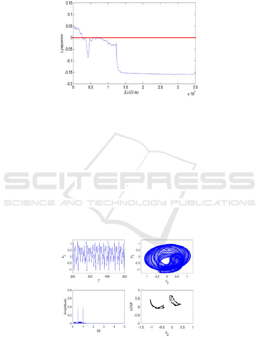
Fig 10. Largest Lyapunov exponent at w=850 rad/s r0=0.04 mm.
(1) When kc
[0,0.2×107] N/m, due to the
lower stator stiffness in the initial phase, the rub-
impact force is much smaller than the nonlinear oil
film force. It can be seen from in Fig.11, the
corresponding value of Largest Lyapunov exponent
is 0.054 at kc=0 N/m. Two strange attractors appear
in the Poincare map. The amplitude spectrum shows
a distinct X/2 discrete peak in fundamental
spectrum. meanwhile, X/2 discrete spectrum
contains continuous spectrum. shaft trajectory
disorder. It indicates that the system is the state of
chaotic motion due to the influence of oil whirl.
(2) When kc
[0.2×107,2.1×107] N/m, as the
stiffness of the stator increases, the rub-impact force
gradually exceeds the nonlinear oil film force.
System motion state experience the general forms
{P-8
P-4
P-2} as the stator stiffness is varied.
When the kc=0.7×10⁷N/m (see Fig.12). The
amplitude spectrum shows a distinct X/2 discrete
peak in fundamental spectrum. there are 4 isolated
points on the Poincare map. the corresponding value
of Largest Lyapunov exponent is less than 0. It
indicates that the motion of rotor is in a steady state.
(3) When kc > 3.1×10⁷ N/m (see Fig.13), due to
the rub-impact force far exceeds the nonlinear oil
force, the system evolved from P-2 motion to P-1
motion. The shaft trajectory is oval shape and its
time domain waveform is regular. The amplitude
spectrum shows the high amplitude in one time
frequency, indicating that the rub-impact force
gradually becomes the dominant factor in the system
and the phase lock is P-1 motion, which indicates
that the increase of stator stiffness weakens the
nonlinear behaviors of the rotor-bearing system.
Fig 11. Time domain response, shaft trajectory, amplitude spectrum and Poincare map at kc=0 N/m.
ICVMEE 2019 - 5th International Conference on Vehicle, Mechanical and Electrical Engineering
182

Fig 12. Time domain response, shaft trajectory, amplitude spectrum and Poincare map at kc=0 .7×107 N/m.
Fig 13. Time domain response, shaft trajectory, amplitude spectrum and Poincare map at kc=2.5×10⁷ N/m.
3.3 Jump Phenomenon
In the high-pressure rotor-bearing system of a
certain type of aeroengine, there has been a
nonlinear vibration phenomenon since assembly. In
the process of aero-engine operation, with the
rotational speed increasing, the aerodynamic engine
can cause the excessive vibration. that’s to say, the
effect of changing the rotational speed of aircraft
engine. The vibration of the rotor-bearing system
will be unstable and then the amplitude of rotor
exists a sudden jump phenomenon when the rotor
speed approaching or exceeding its 1st or 2nd order
critical speed.
The vibration amplitude jumps in a short time,
either from small to large, or from large to small (C.
Li, and L.Shuai-ying, 2013).
With respect to this engineering problems, this
section studies the dynamic characteristics of the
rotor-bearing system during acceleration and
deceleration section. The system parameters are
taken from in Table 1. The 4th-order Runge-Kutta
method is used to study the rotor-bearing system
response curve.
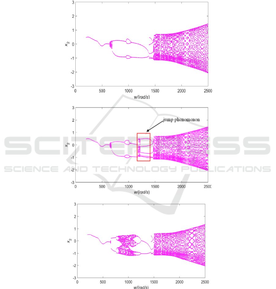
As is shown in Fig. 14(a) (b) provides a
comparison of bifurcation diagrams in the same
condition (e=0.045), Overall, the dynamic
characteristics exhibited by two diagrams are quite
similar as (w) increases. But after the rotor passes
the first-order critical speed. the rotor system
responds transits from the period 2 movement to the
short-term chaotic motion in the deceleration
section(see Fig.14(b)). It indicates that the rotor-
bearing system experiences a short-term instability
after passing the critical speed range [1250, 1200]
rad/s. When the eccentricity e=0.050, as shown in
Fig.14(c), (d), the rotor-bearing system response
experiences: {p4
chaos
p5} at w
[1350,1200] rad/s(see Fig.17(d)). Compared with
e=0.045, the chaotic motion interval becomes wider.
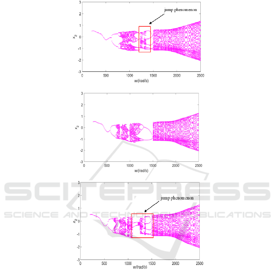
At the eccentricity e=0.055(see the Fig. 14(e) (f)), it
can be seen that the system takes a series of motion:
Nonlinear Coupled Dynamic Characteristics and the Stability of Rotor-Bearing System under Rub-Impact and Oil-Film Forces
183
{chaos
P-2
chaos
P-5} in the deceleration
section at w
[1500,1100] rad/s(see Fig.14(f)). the
system has a large jump phenomenon in this
interval. Through numerical simulation, the rub-
impact system will produce the jump phenomenon at
a certain stage after the critical speed. As the mass
eccentricity increases, the jumping phenomenon of
the system will become more and more obvious, and
the instability of system will occur in advance. In the
process of engineering assembly, the rotor
concentricity should be improved, and the
eccentricity should be reduced as much as possible.
(a)
(b)
(c)
ICVMEE 2019 - 5th International Conference on Vehicle, Mechanical and Electrical Engineering
184
(d)
(e)
(f)
Fig 14. Bifurcation diagram of the rotor-bearing system response in x direction in certain condition
:
(a)
e=0.045,
accelerating section,
w∈[200,2500]rad/s
(b)
e=0.045,
decelerating section,
w∈[2500,200] rad/s
(c)
e=0.050,
accelerating section,
w∈[200,2500]rad/s
(d)
e=0.050,
decelerating section,
w∈[2500,200]rad/s
(e)
e=0.055,
accelerating section,
w∈[200,2500]rad/s
(f)
e=0.055,
accelerating section,
w∈[2500,200]rad/s
4 CONCLUSIONS
In this paper, the nonlinear dynamic equation of the
rotor-bearing system is established by Lagrange
equation considering the rub-impact force and
nonlinear oil film force. The nonlinear rotor
dynamic characteristics are investigated numerical
simulation. The largest Lyapunov exponent, time
domain response, shaft trajectory, phase-plane,
amplitude spectrum, Poincare map are applied to
analyze the nonlinear vibration of rotor-bearing
system. Numerical calculations indicate that the
Nonlinear Coupled Dynamic Characteristics and the Stability of Rotor-Bearing System under Rub-Impact and Oil-Film Forces
185

excitation frequency, stator stiffness and mass
eccentricity exist rich nonlinear characteristics for
the rotor-bearing system, such as period doubling
bifurcation, quasi-period and chaotic motion.
Through numerical calculations, the following
conclusions are obtained:
(1) The Excitation frequency has a great
influence on dynamics response of rotor-bearing
system. In the low excitation frequency phase, the
nonlinear oil film force mainly affects the dynamic
characteristic of rotor-bearing system and presents
the oil film whirl. periodic- doubling, and chaotic
motion can be observed through numerical
calculation. When the high excitation frequency
phase, the rub-impact force is mainly affecting
dynamics behaviors of the rotor-bearing system. The
response of rotor-bearing system is mainly based on
oil film oscillation and the only the quasi-period
motion can be found in the high speed.
(2) The response of rotor-bearing system is in
chaotic motion at the kc
[0,0.2×107] N/m. and the
response of system is the periodic-doubling at the kc
[0.2×107,2.1×107] N/m. The response of rotor-
bearing system responds to Phase lock for Period-1
motion at the kc
3.1×10⁷ N/m. With the increases
of stator stiffness is beneficial to simplify the
response dynamic response of the system. the
response of the rotor-bearing system gradually
transforms from chaotic motion to periodic motion.
(3) In the process of acceleration and
deceleration of the rotor-bearing system with rub-
impact, the system exists the jump phenomenon.
Under the large unbalanced condition, the jumping
phenomenon of the nonlinear vibration is more
obvious. In the engineering assembly, the
concentricity of rotor should be increased to reduce
the eccentricity as much as possible.
ACKNOWLEDGMENTS
This work is supported by the National Basic
Research Program (973 Program) of china (Grant
No. 2013CB035706).
The Graduate Research Innovation Project funding
of Central South University (No. 2019zzts256).
REFERENCES
C. Li, L. Shuai-ying; 2013, Bistable vibration
characteristics of disk-rod-fastening rotor with squeeze
film dumper. Journal of Aerospace Power 28, 2044-
2049 (2013).
D.-y. Wang, 1998, Rotating Machinery Rotor-Static
Rubbing Vibration Characteristics. Airspace actuator,
37-41+36 (1998).
L.-H. Yang, W.-M. Wang, 2014, A new nonlinear
dynamic analysis method of rotor system supported by
oil-film journal bearings. Appl Math Model 38, 5239-
5255.
L. K. Zhang, Z. Y. Ma, 2016, Vibration analysis of
coupled bending-torsional rotor-bearing system for
hydraulic generating set with rub-impact under
electromagnetic excitation. Archive of Applied
Mechanics 86, 1665-1679.
L.Liu and D. Q. Cao, 2015. Dynamic characteristics of a
disk-drum-shaft rotor system with rub-impact.
Nonlinear Dynamics 80, 1017-1038.
M. Lee, J. Lee, G. Jang, 2015, Stability analysis of a
whirling rigid rotor supported by stationary grooved
FDBs considering the five degrees of freedom of a
general rotor-bearing system. Microsyst Technol 21,
2685-2696.
Q.-k. Han, T. Yu, 2010, Nonlinear vibration analysis and
diagnosis method for faulty rotor system. (Science
Press).
W. Li, 2002, Common Characteristics in Failure Analysis
of Aeroengine Blade. Experimental Study of Gas
Turbine, 28-30+53.
Y. Zhang, W. M. Wang, 2010, the nonlinear dynamic
behavior of double-disk isotropic rotor system with
rub-impact. Mechanical Engineering and Green
Manufacturing, Pts 1 and 2, 1483-1487.
ICVMEE 2019 - 5th International Conference on Vehicle, Mechanical and Electrical Engineering
186
