Analysis and Design of Wireless Charging System based on SSC
Yaya Wang
1, a
, Guokun Xie
1
, Kai Zheng
1
1
Electrical Automation, Xi`an Traffic Engineering Institute, Mei Bei west road, Binhe new district, Xian, China
Keywords: Resonance, wireless charging, coupling coil, chopper frequency.
Abstract: Based on the series resonance compensation topology structure as the research foundation, taking charging
electric cars as the object, using the simulation software to build a wireless charging system T model
equivalent circuit, by dealing with choosing the right frequency sweep chopping frequency, using the
method of regulating control, solves the problem of wireless power transmission efficiency is low and the
rate of change, and finally the use of Ansoft electromagnetic simulation software Maxwell3D theory
analyses the mutual inductance coil and the relationship between the transmission distance, to the study of
wireless charging of electric cars, has very important significance.
1 INTRODUCTION
Comrade Xi Jinping pointed out in the report to the
19th national congress that "clear water and green
mountains are golden mountains", adhering to the
basic state policy of resource conservation and
environmental protection, electric energy as a kind
of clean energy is widely used in all walks of life,
and electric vehicles as a new type of energy
transportation is an inevitable development trend. As
a safe, convenient and adaptable Power Charging
technology, Wireless Power Transfer (WPT) is the
key technology for the development of pure electric
vehicles in the future. If we master this technology,
we will have the right to speak in this field. Many
companies have designed wireless charging systems
with power up to 3kw (
L. Chen, S. Liu, Y. C. Zhou
and T. J. Cui
, 2011), but there are still some
research points that need to be improved, such as:
how to reduce the coil size to reduce the system cost
when the same power is transmitted, how to make
the system better adapt to the complex situation of
different coil displacements, how to improve the
transmission efficiency while reducing the loss, etc.,
are hot issues in current research. Based on previous
studies, this paper adopts the transformer wireless
charging control system to regulate the output
power, and mainly analyzes the influence of the
characteristics, frequency characteristics and
coupling coefficient of the series-series resonant
topological switch on the output power and
transmission efficiency.
2 S-S RESONANT TOPOLOGY
MODEL ANALYSIS
The main principle of wireless charging technology
is that the transmitter coil and the receiver coil have
the same resonant frequency. To achieve this
purpose, an appropriate resonant compensation
capacitor is usually added to the two coils.
According to the transmitting terminaland receiving
terminal network connection relationship, WPT
system topology structure can be divided into series
-series (S-S), series and parallel (S-P), parallel and
series (P-S), parallel-parallel (P-P) of these four
basic structure, the series-series(S-S) resonant
topology is the best power wireless transmission
resonant topology (Yongsheng Fu, Lei Shi,
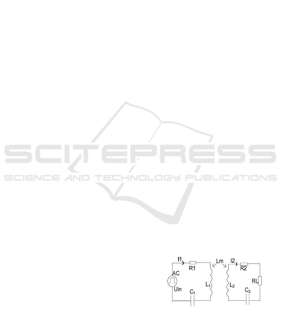
Kevin(hua) Bai, 2014). Figure 1 is transformer
equivalent model of (S-S) resonant.
Figure 1. S-Stransformer equivalent model.
It is assumed from figure 1 that:
336
Wang, Y., Xie, G. and Zheng, K.
Analysis and Design of Wireless Charging System based on SSC.
DOI: 10.5220/0008480903360340
In Proceedings of 5th International Conference on Vehicle, Mechanical and Electrical Engineering (ICVMEE 2019), pages 336-340
ISBN: 978-989-758-412-1
Copyright
c
2020 by SCITEPRESS – Science and Technology Publications, Lda. All rights reserved

1
111
*
**
Cw
j
LwjRZ
(1)
2
222
*
**
Cw
j
LwjRRZ
L
(2)
mm
LwX *
(3)
mm
LwjZ **
(4)
Where, R1 is the internal resistance of L1 of the
primary coil, R2 is the internal resistance of L2 of
the secondary coil, and RL is the load, C1 and C2
are the resonant capacitors of the primary side and
the secondary side respectively. Lm is the mutual
inductance of the primary and secondary coil.
Therefore, it can be known from the transformer
principle that:
0**
**
221
211
ZIZI
UIZIZ
m
inm
(5)
Equation 5 shows that:
2
21
2
2
21
2
1
)*(*
***
)*(*
*
m
inm
m
in
LwZZ
ULwj
I
LwZZ
ZU
I
(6)
Total power input of circuit:
cos*
|)*(*|
||*
)*Re(
2
21
2
2
1
m
in
inin
LwZZ
ZU
IUP
(7)
Total power output of circuit:
|])*(*[|
)*(**
*||
22
21
22
2
2
m
mLin
Lout
LwZZ
LwRU
RIP
(8)
Total circuit efficiency:
cos*|])*(*[*|
*)*(
2
212
2
m
Lm
in
out
LwZZZ
RLw
P
P
(9)
Maximum transmission efficiency:
%100*
])*()()[(
*)*(
2
212
2
mLL
Lm
LwRRRRR
RLw
(10)
3 COIL MODEL AND CIRCUIT
SIMULATION
3.1 Coil Model
By equation (10) with known as in resonance circuit
and load coil of the case, the transmission efficiency
of circuit is only related to the mutual inductance
coil, the greater the mutual inductance transmission
efficiency is higher. According to the principle of
magnetic coupling, when the same wire is used to
form a coil, the larger the coil area, the greater the
mutual inductance value and mutual inductance
coefficient will be. So the method to improve the
transmission efficiency of system is within the
allowed space set up the large area of the coil.
This design by using the finite element analysis
software Ansys/Maxwell circuit parameters of the
simulation to get the best parameters based on figure
2 inject 50 KHZ high frequency ac signal to the coil,
the magnetic field lines toward the trend and
magnetic field strength.
3.2 Principles of WPT
Principle of electric vehicle charging system: power
frequency alternating current (ac) is obtained by
rectifying filtering first stable direct current (A.K.
RamRakhyani, S.Mirrabbasi, and C.Mu, 2018), then
through high frequency inverter for high frequency
square wave ac, repass transmitter resonant
compensating network and launch coil to make work
in resonant state, when transmitting circuit
frequency and receiving coil and the receiver equals
the compensating network frequency, magnetic field
energy can be transmitted through magnetic
resonance (NMR), receiving coil get electricity
finally through the high frequency output rectifier to
the electric car battery.
3.3 Circuit Simulation
For s - s resonant topology, switch frequency
directly affects the system's output power to the total
loss, so the simulation of the system do sweep with
the equivalent circuit of transformer, zero point of
resonance analysis impedance has two, as shown in
figure 3 so this design choice than 50 KHZ and
chopping frequency can be changed as a resonance
point, make the output power under control.
Analysis and Design of Wireless Charging System based on SSC
337
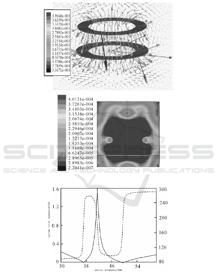
Figure 2. Lines of magnetic force coupling coil and the magnetic field intensity distribution.
Figure 3. System total impedance and phase VS switch frequency.
According to the working principle of WPT and
simulation of coil parameters, the system simulation
waveform is shown in figure 4.
Simulation waveform shows by the figure 4
system of charging: when adjusting the input dc
voltage of 220 v, the charging power of about 345
ICVMEE 2019 - 5th International Conference on Vehicle, Mechanical and Electrical Engineering
338
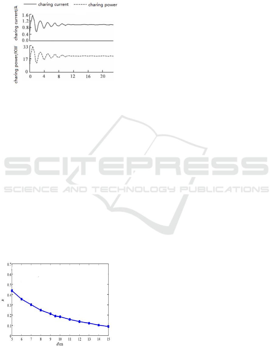
w, system about 60 ms into a stable state, the
charging waveform smooth system safe and reliable
operation.
Figure 4. System simulation waveform.
4 COUPLING COEFFICIENT
MEASUREMENT AND
ANALYSIS
Coupling coefficient is the physical quantity that
reflects the coupling degree of transmitting coil and
receiving coil most directly. The coupling
coefficient varies with the transmission distance of
the system. The change of coupling coefficient
directly affects the output power and transmission
efficiency of the system.
Can be seen from the figure 5, the farther the
transmission distance, the smaller the mutual
inductance between the two coils M, the smaller the
coupling coefficient k, and the smaller the coupling
coefficient of output power and transmission
efficiency is smaller, so, choose appropriate
transmission distance is the factors affecting the
output power and the transmission efficiency is very
important.
5 CONCLUSION
Based on the s-s resonant topological structure, the
design obtains the model parameters and chopper
frequency of the wireless charging system through
simulation analysis, and obtains the charging
simulation waveform by simulating the T equivalent
circuit diagram of the wireless charging system. It is
pointed out that the system must detect the changes
of coil mutual inductance and leakage inductance in
real time according to the changes of relative
displacements between coils in order to charge
stable. The relationship between coil mutual
inductance M and transmission distance d is
analyzed theoretically.
ACKNOWLEDGEMENTS
Scientific research project of Shaanxi provincial
education department in 2019, search and design of
voltage regulating wireless charging system based
on SSC.
REFERENCES
A.K. RamRakhyani, S.Mirrabbasi, and C.Mu, “Design and
Optimization of Resonance-Based Efficient Wireless
Power Delivery System for Bionmedical Implants,”
IEEE Trans. Biomed. Circuit Syst., vol.5, pp. 48-63.
Http: // info. xcar. com. cn/ 201501/news _ 1750736 _
1.html.
L. Chen, S. Liu, Y. C. Zhou and T. J. Cui, “An
optimizable circuit structure for high-efficiency
wireless power transfer”, IEEE Trans. Ind.
Electron.,vol.60, no.1, 2011, pp. 339 –349.
Yongsheng Fu, Lei Shi, Kevin (hua) Bai. “High-
Frequency Wireless Charging System Study Based on
Normally-off GaN HEMTs,” IEEE Wide Bandgap
Device and Application Conference (WiPDA 2014-
10).
Analysis and Design of Wireless Charging System based on SSC
339

Figure 5. Relation curve between coupling coefficient and
transmission distance.
ICVMEE 2019 - 5th International Conference on Vehicle, Mechanical and Electrical Engineering
340
