
The Research on Control System of Pipeline Dredging Robot based
on Simulink
Jiman Luo
a
, Lulu Dai
b
Shenyang Jianzhu University, Shenyang, China
Keywords: Pipe dredging robot, PI algorithm, double closed loop control, control system
Abstract: In order to control the new pipe dredging robot more accurately and ensure the stable operation of the
robot in the harsh environment, the motion control system of the robot is designed and the PI algorithm
based on double closed-loop speed control system for walking unit of wheeled mechanism is studied.
According to the Simulations by Simulink and experimentations of the above control methods, it was
indicated that the motor speed can be stabilized at the set speed value under the disturbance of load
change, and the dynamic performance is also stable. Finally, a double closed-loop speed control system
with strong anti-load fluctuation capability is adopted. The control method satisfied the requirements of
the working condition of the robot in a complex environment and realized that the precise control of the
motion state of the robot.
1. INTRODUCTION
At present, many universities and companies are
working on the study of pipeline robots and have
made considerable achievements. However, there are
still few robots that can dredge automatically, and the
control system of dredging robots is still not perfect.
A dredging robot that its core controller is 51 MCU
was developed in Changzhou University. The
pressure value is automatically adjusted to its own
size to adapt to different diameter pipes, which
improves the adaptability of dredging robots. A
detailed study on the pipeline inspection robot control
and navigation system is studied in Shanghai Jiao
tong university. The intelligent control of pipeline
robot autonomous path planning, navigation and
action is realized. Those dredging robots only have
the function of checking the internal damage of the
pipeline and replacing the staff to complete the cable-
carrying operation (Chen Li Gang, 2016), the self-
cleaning ability is poor. Therefore, the research of the
dredging robot control system still needs to be further
to improve the automation level of the dredging robot.
According to the mechanical structure and
working requirements of the robot, the design of the
whole control system is carried out to enhance the
controllability of the robot and achieve independent
dredging. In order to ensure the smooth and reliable
movement of the robot, it is necessary to research on
the motor control algorithm and the speed control
system deeply.
2. THE ROBOT STRUCTURE
AND CONTROL SYSTEM
2.1 The Mechanical System
Structure of Pipeline Dredging Robot
The structure of the dredging robot is shown in Figure
1. Considering drainage pipe is mostly circular, the
shape of the robot is designed with a cylindrical
structure. The mechanical body is mainly composed
of three parts, which are a wheeled walking
mechanism, a step-push mechanism and dredging
mechanism. The step pushing mechanism is an
auxiliary mechanism for the pipeline robot. When the
three walking units are all in a slipping state, the step
pushing mechanism starts to assist robot to advance.
The dredging mechanism is the core component of
the pipeline dredging robot to remove the sludge from
the pipeline.
Luo, J. and Dai, L.
The Research on Control System of Pipeline Dredging Robot based on Simulink.
DOI: 10.5220/0008480803290335
In Proceedings of 5th International Conference on Vehicle, Mechanical and Electrical Engineering (ICVMEE 2019), pages 329-335
ISBN: 978-989-758-412-1
Copyright
c
2020 by SCITEPRESS – Science and Technology Publications, Lda. All rights reserved
329
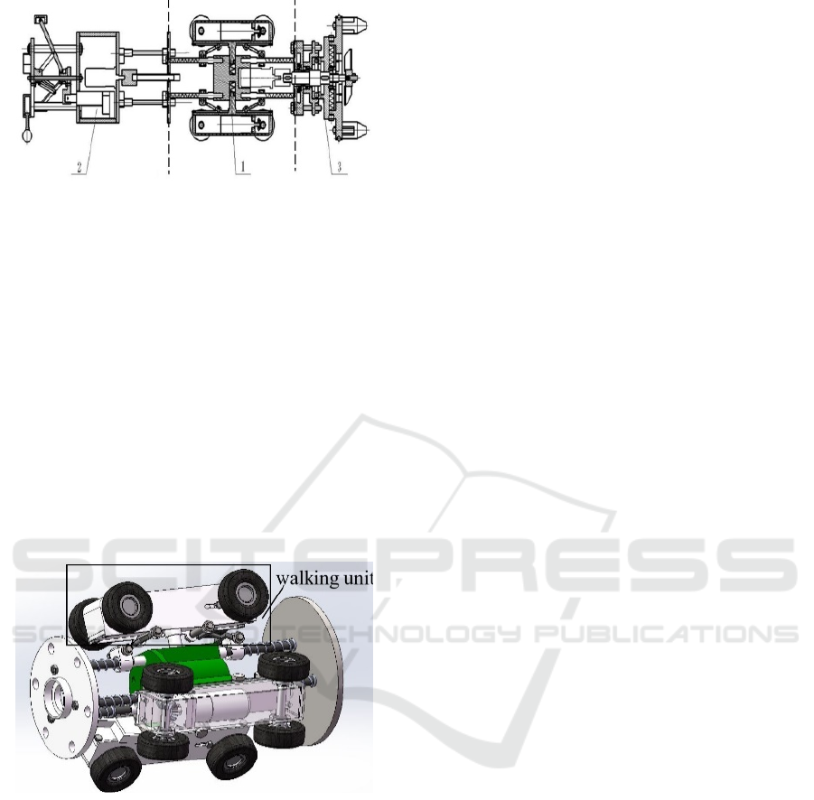
1. Wheeled walking mechanism 2. step-push mechanism
3. Dredging mechanism
Figure 1. The picture of robot structure.
It can be seen from Fig.1 that the wheeled
traveling mechanism is in the middle position of the
whole machine, and is the main driving mechanism
for the robot. The structure of the wheeled walking
mechanism is shown in Figure 2. It is mainly
composed of three groups of walking units, and the
three walking units are evenly distributed on the
circumference, each walking unit is controlled by a
motor. In an ideal state, the speed of the three
independent drive motors should be same, so the
control system needs to have better speed regulation
capability, so that the robot can move smoothly and
reliably.
Figure 2. Wheeled walking mechanism.
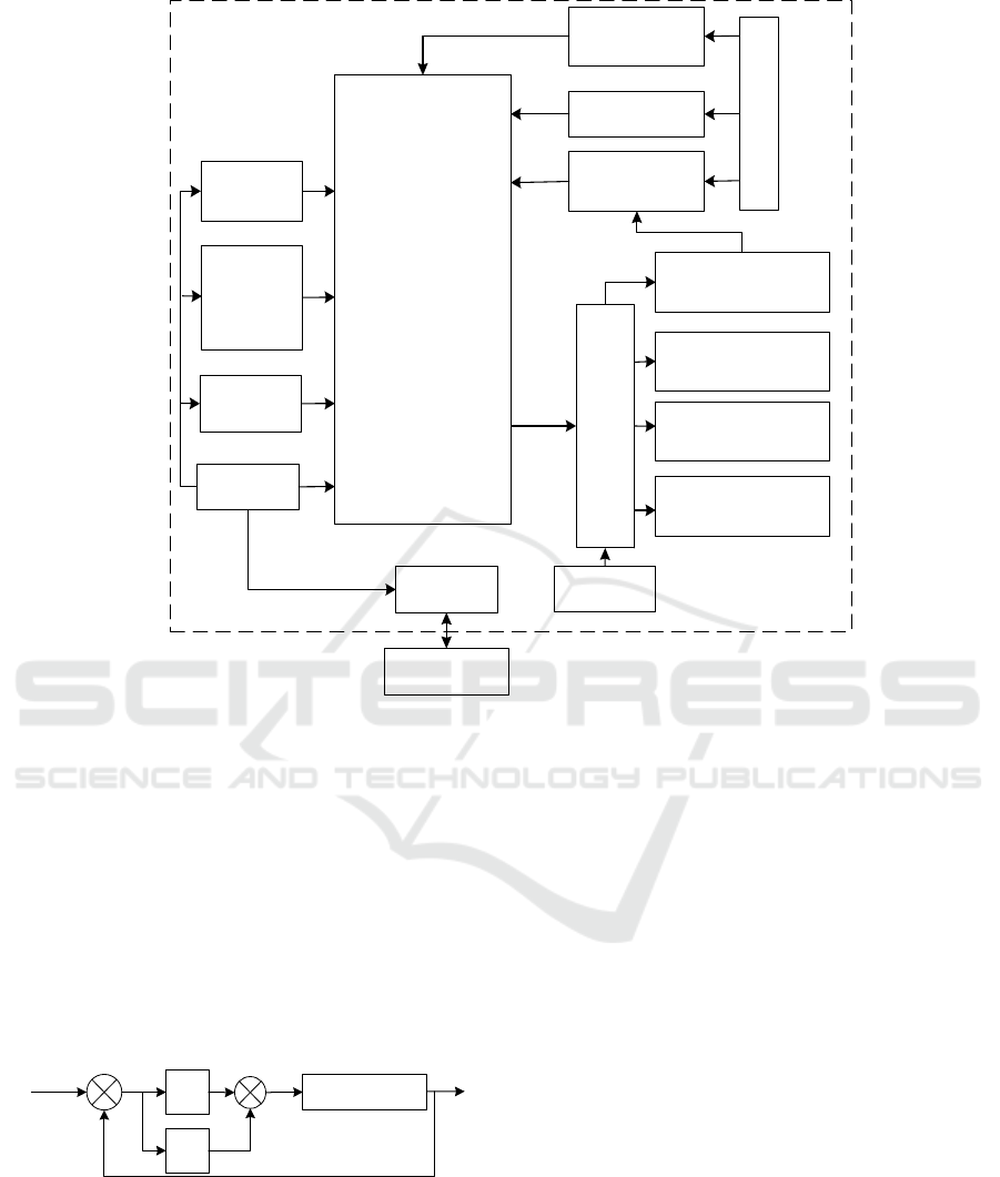
2.2 The Hardware Configuration of
Control System
According to the purpose and requirements of the
design, a system diagram as shown in Figure 3. The
robot control system is divided into the following
parts according to functions, including control
module, input module, output module and
communication module. STM32 microcontroller is
control module; the input module is composed of a
detecting module, a speed measuring module and a
photoelectric module; the output module is composed
of a motor drive module, a drive motor and an electric
push rod; the communication module is the blue-tooth
module (Qian Xiao Long, 2017). As the core control
device of the system, STM32 MCU is responsible for
the precise control of each motor, the identification of
the host computer commands and the transmission of
data (Xie Shao Chun, 2018). The motor drive module
amplifies the small signal generated by the controller
to a high power voltage level and current level
sufficient to drive the motor. The host computer sends
commands to the lower computer through the blue-
tooth module. At the same time, the information
collected by various sensors and video modules is
also fed back to the host computer.
3. RESEARCH AND SIMULATION
OF SPEED CONTROL SYSTEM
The robot driving control system is the core of
completing the operation successfully, and ensure
that it has an excellent capability of passivity anti-
overturning and obstacle resistance.
Now the motor control system mostly adopts the
method of closed-loop feedback to improve the
performance indexes. The single-closed loop control
with negative speed feedback and double closed-loop
control of current and speed are widely used. Both of
these control methods can make the output speed
follow-up and stable without static error. In this
paper, the simulation of these two control systems are
carried out by Simulink, and compared effects of the
two control systems (Li Xian, 2015).
3.1 PID Control Algorithm
PID is a control method with stable effects and wide
application (Hung Ping, 2017). It is widely used in
control systems with clear mathematical models. The
proportional link can play a role in speeding up the
adjustment; the integral link can weaken the steady-
state error; although the differential link helps to
overcome the system oscillation and reduce the
system overshoot, it is sensitive to the noise of the
input signal, making the control system susceptible to
the high frequency electromagnetic interference.
ICVMEE 2019 - 5th International Conference on Vehicle, Mechanical and Electrical Engineering
330
micro-computer
STM32
Reset
circuit
3.3V
Crystal
oscillator
circuit
Wireless
PC-software
GPS
Onboard
software
Pressure
detection
Photoelectric 5V
Speed
measuring
Motor
drive
12V
Motor5
(dredging mechanism)
Motor1、2、3
(wheeled mechanism)
Electric putter
(step-push mechanism)
Motor4
(
step-push mechanism)
Figure 3. System block diagram.
In practical applications, the three links of
proportional, integral and differential can be
combined according to the needs. In order to achieve
a fast and stable control effect, the proportional and
integral links are finally selected for motor speed
control. The PI controller is consisted of three parts:
measurement, comparison and execution. As shown
in Figure 4, firstly setting a command value, then it is
compared with the feedback value to get the system
deviation. After the PI operation, the control quantity
is output.
Kp
-
e(t)
Ti
+
+
+
Controlled object
u(t)
y(t)
Figure 4. Schematic diagram of PI control.
3.2 The Control System Speed of
Single Closed Loop
It can be seen from Figure 5 that the single closed-
loop control system with the negative speed feedback
can obtain the deviation speed (e) by comparing the
commanded speed value (n*) with the feedback speed
value (n). After the corresponding operation is
performed by the PI controller, the output signal
adjusts the PWM duty cycle to provide an appropriate
driving voltage to the motor, and finally adjusts the
motor speed (Wang Gui Yu, 2018) .The control
system can quickly and smoothly make the motor
reach the commanded speed value and maintain the
ability of follow-up; and it will weaken the
fluctuation caused by the load change.
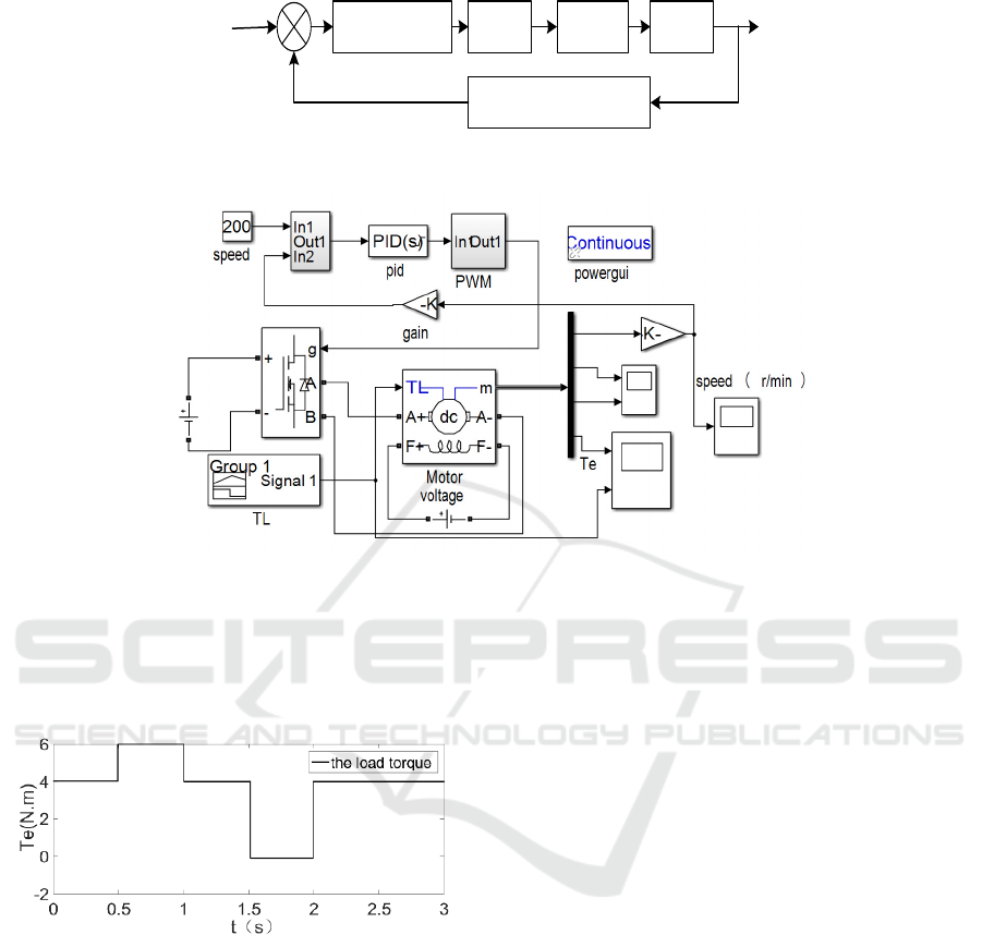
According to Figure 5, established the simulation
model as Figure 6. Setting the given speed is
200r/min, then compared it with the motor feedback
speed, and obtain the deviation speed. After the PI
regulator calculates, the PWM control signal is
applied to the corresponding switch tube, and finally
achieves the purpose of speed regulation (Wang Dian
Jun, 2008).
The Research on Control System of Pipeline Dredging Robot based on Simulink
331
PIDcontroller PWM driver Motor
Speed measurement
n
-
e
n*
Figure 5. Speed control system with speed feedback.
Figure 6. The picture of simulation model.
To simulate motor load changes, the load torque
(TL) outputs in step pulse. The initial load torque is
set to 4 N. m, and then changes every 0.5 s, as shown
in Figure 7.
Figure 7. The change of load torque.
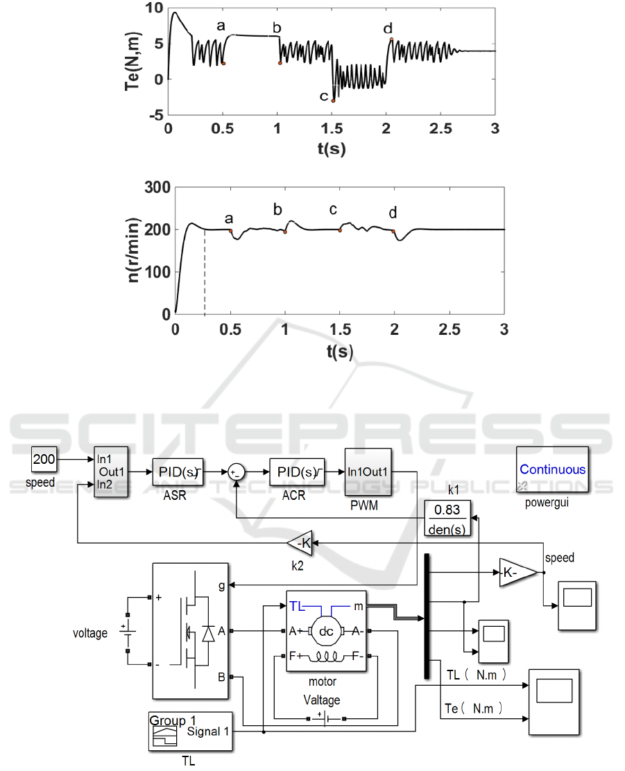
Figure 8 is the result of the speed closed loop
control system simulation, where in Fig. 8(a) is the
torque of the system Fig. 8(b) is the speed of the
system changing with simulation time.
The analysis of simulation results:
As can be seen from Figure 8 (a), the torque at the
start of the motor is large, reaching 7.8 N. m, and then
stabilized near the set value. And the actual output
torque of the motor follows the setting value. At the
point of a, the set value jumps from 4 N. m to 6 N. m,
the actual output torque of the motor fluctuates
greatly.
It can be seen from Figure 8 (b) that the speed of
the motor is obviously overshoot when the motor
starts, and is stable at the set value in 0.2s; When the
load torque changes, the motor speed fluctuates
greatly, after a certain beating, it can return to the set
speed valve.
3.3 The Control System of Current
and Speed Double Closed Loop
As shown in Fig.9, the current loop is an inner loop,
and the speed loop is an outer loop. The output of the
speed regulator (ASR) is the given of current
regulator (ACR). The output of the ACR is used to
adjust the duty cycle of the PWM signal, thus forming
a double closed-loop control system. In this system
the set value of the load torque is the same as the
single-loop simulation model, as shown in Figure 9.
ICVMEE 2019 - 5th International Conference on Vehicle, Mechanical and Electrical Engineering
332
(a) Torque diagram of the system.
(b) The speed of the system.
Figure 8. The picture of simulation result.
Figure 9. The picture of simulation Model.
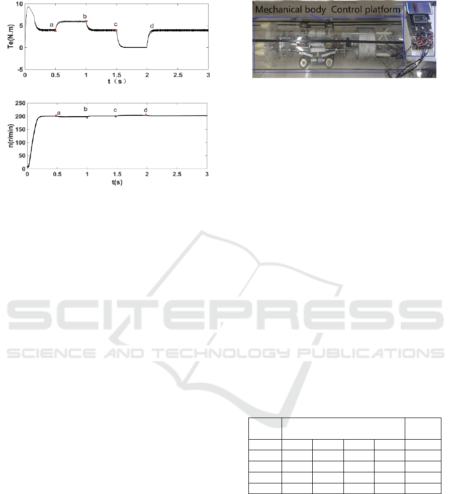
Figure 9 is the result of the double closed loop
control system simulation, where in Figure 10(a) is
the torque of the system Figure 10(b) is the speed of
the system changing with simulation time.
The Research on Control System of Pipeline Dredging Robot based on Simulink
333
(a) Torque diagram of the system.
(b) The speed of the system.
Figure 10. The picture of simulation result.
As can be seen from Figure 10 (a), compared with
the speed closed-loop control system, the actual
output torque is more quickly stabilized at 4 N.m. The
motor output torque varies with load torque and there
is a small amount of fluctuation.
It can be seen from Figure 10 (b) that during the
starting process of the motor, the motor speed hardly
has overshoot and is relatively stable compared with
the speed closed loop control system; when the load
torque fluctuates up and down, the influence on the
motor speed is small.
In summary, the double closed-loop control
system has good advantage in speed -following and
strong resistance to load fluctuations. The system
runs smoothly, with excellent static and dynamic
performance. And the PWM pulse width modulation
technology directly regulates the magnitude and
polarity of the output voltage, which can realize the
smooth speed regulation of the system. Considering
that the load will change when the dredging robot is
working, the control method with double closed-loop
is used to weaken the fluctuation caused by the load
change, and the speed control of the robot wheel drive
system is realized.
4. EXPERIMENT
The test platform is mainly composed of the
prototype of pipeline robot, a control system and a
simulated pipeline environment, as shown in Figure
12. This experiment has two steps, such as the test of
whole machine function and the speed test of the
wheel drive mechanism motor.
Figure 11. The experiment platform of robot.
4.1 The Test of Machine Function
In order to verify the stability of the control system
and test functional modules of the robot are working
properly, the function test of the whole machine is
carried out firstly. When the robot is placed in the
horizontal pipeline, sent the corresponding
instruction to test the function realization of the three
parts of the robot. Tested that the robot moved stably
and each function is according to the design; there is
no significant jitter at the moment of start and stop,
indicating that the control system is effective and
reliable.
4.2 The Speed Test of the Wheel
Drive Mechanism Motor
As shown in Figure 5, the wheel drive mechanism
motor adopts a double closed-loop control system
based on PID algorithm. In order to test whether the
motor speed can follow a given change, it sets five
values. The speed feedback time interval is 1ms. The
actual measurement results are shown in Table 1.
Table 1. The results of measurement.
set
r/min
measurement results
r/min
error
%
160 157 161 163 162 1.8
180 176 181 183 183 1.6
200 196 199 205 203 1.5
220 215 221 224 223 1.3
240 239 241 243 240 1.2
It can be seen that the motor speed average error
is 1.48%, and the overshoot is small. The system has
good follow-up and dynamic steady-state
performance. With the increase of the set speed, the
error of the speed is gradually reduced. It can be
explained that the double closed-loop speed control
system designed has good dynamic-state and steady-
state performance. The system can achieve a response
fast and a stable output.
ICVMEE 2019 - 5th International Conference on Vehicle, Mechanical and Electrical Engineering
334

5. CONCLUSION
According to the walking mode of the dredging robot,
the design of robot control system and the wheel drive
motor speed control system was carried out. the
simulation analysis and experimental verification
were also carried out, the following conclusions were
obtained.
(1) It has been verified by experiments that the
dredging robot control system has good
controllability and autonomy, and can achieve precise
control of the robot's operation in the pipeline.
(2) The model of two systems are established in
Simulink, which are the control system with single
closed loop and double closed loop, and compared the
effects of the two control systems. The results show
that the double closed-loop control system has good
speed follow-ability, strong resistance to load
fluctuation and excellent, dynamic performance. It is
verified by experiments.
The results show that the control method and
speed control system meet the design requirements
and can realize the precise control of the speed of the
robot wheel drive system.
ACKNOWLEDGEMENT
Thank the support of provincial natural science fund
guidance program (201602620) and general scientific
research project of Liaoning provincial education
department (LJZ2016018).
REFERENCES
Chen Li Gang, and Yuan Yong Bao (2016). The principle
and application case tutorial of MCU, Central Radio
and Television University Press. Beijing, 2nd edition.
Hung Ping, and WANG Ying. et al.2017. DC motor fuzzy-
PID control system based on STM32. Journal of
Mechanical & Electrical Engineering, 34(4), p. e 380-
385.
Li Xian, and Luo Zhi Wei.2015. Proficient in
MATLAB/Simulink system simulation. Beijing,
Tsinghua University Press, 1th edition.
Qian Xiao Long, and Yan Shi Jie. 2017. Electric drive
control system. Beijing, Metallurgical Industry Press,
1th edition.
Wang Dian Jun, and Li Run Ping. et al. 2008. Research
progress of pipeline robot. Machine tool and hydraulic,
36(4), p. e 185-187.
Wang Gui Yu, and Feng Ying Bin. et al. 2018. Research on
synchronous simulation of wheel pipeline robot.
Computer Simulation, 35(4), p. e 306-310.
Xie Shao Chun, and Chen Yang. et al. 2018. The design of
robot motion precision control system based on
STM32.Technology Innovation and Application,
35(16), p. e 35-37.
The Research on Control System of Pipeline Dredging Robot based on Simulink
335
