
BP Neural Network PID Control of Stable Platform
Hesong Xia
1, a, *
and Jie Ma
1, b
1
Harbin Insititute of Technology, School of Aerospace, Control and Simulation Center, China
Keywords: Stable platform, BP Neural Network, PID.
Abstract: Stable platform has been widely used in modern weapons and civil equipment due to its ability to isolate
carrier interference, and research on key technologies for stable platforms has very important practical
significance and application value. In this paper, the three-axis stabilized platform is taken as the research
object. A control system based on multi-loop control structure is designed around the mathematical model
of DC torque motor. The design and implementation of servo control system are carried out by using
classical PID and BP neural network PID control algorithm respectively. The BP neural network PID
control algorithm is verified by MATLAB simulation. Compared with classical PID control algorithm, it
has higher control precision and anti-interference ability.
1 INTRODUNCTION
This topic is based on the design of the control
system of stable platforms, focusing on the design of
the attitude control loop controller, and comparing
the difference of the tracking effect of the stable
platform when the controller adopts the classical
PID control method and the BP neural network PID
control method respectively.
2 DESIGN OF STABLE
PLATFORM SERVO STSTEM
The main function of the three-axis stabilized
platform control system is to isolate the carrier's
disturbance. The system control structure is shown
in Fig. 1. The stability loop uses dual-loop control,
the inner loop is the frame angle control loop of the
three-axis turntable, and the outer loop passes the
fiber. The inner loop controller adopts the series lead
correction design method to make its tracking
performance meet the requirements of the double ten
index (Wang Z S, Nian li LU, 2005). The outer loop
controller adopts the classic PID controller and the
adaptive PID controller, so that the stable turntable
can isolate the carrier's disturbance
f
.
2.1 Design of Frame Angle Control
Loop
In order to obtain the transfer function of the loaded
motor, the third-order transfer function is fitted to
the open-loop frequency characteristic of the loaded
motor through the MATLAB system identification
toolbox. The obtained identification result is shown
in Fig. 2.
The frame angle control loop controller adopts
the series correction controller, which respectively
adds the inertia link, the lead link, the delay link, the
input sinusoidal signal with the amplitude of 0. 5V
and the frequency of 1Hz, the tracking amplitude
error of the frame angle control loop is 3. 62%,
obtained by the FFT analysis of the signal and the
phase error is -4. 52°, which satisfies the double ten
index (Deng K, Cong S, Shen H, 2011).
Xia, H. and Ma, J.
BP Neural Network PID Control of Stable Platform.
DOI: 10.5220/0008387703230328
In Proceedings of 5th International Conference on Vehicle, Mechanical and Electrical Engineering (ICVMEE 2019), pages 323-328
ISBN: 978-989-758-412-1
Copyright
c
2020 by SCITEPRESS – Science and Technology Publications, Lda. All rights reserved
323
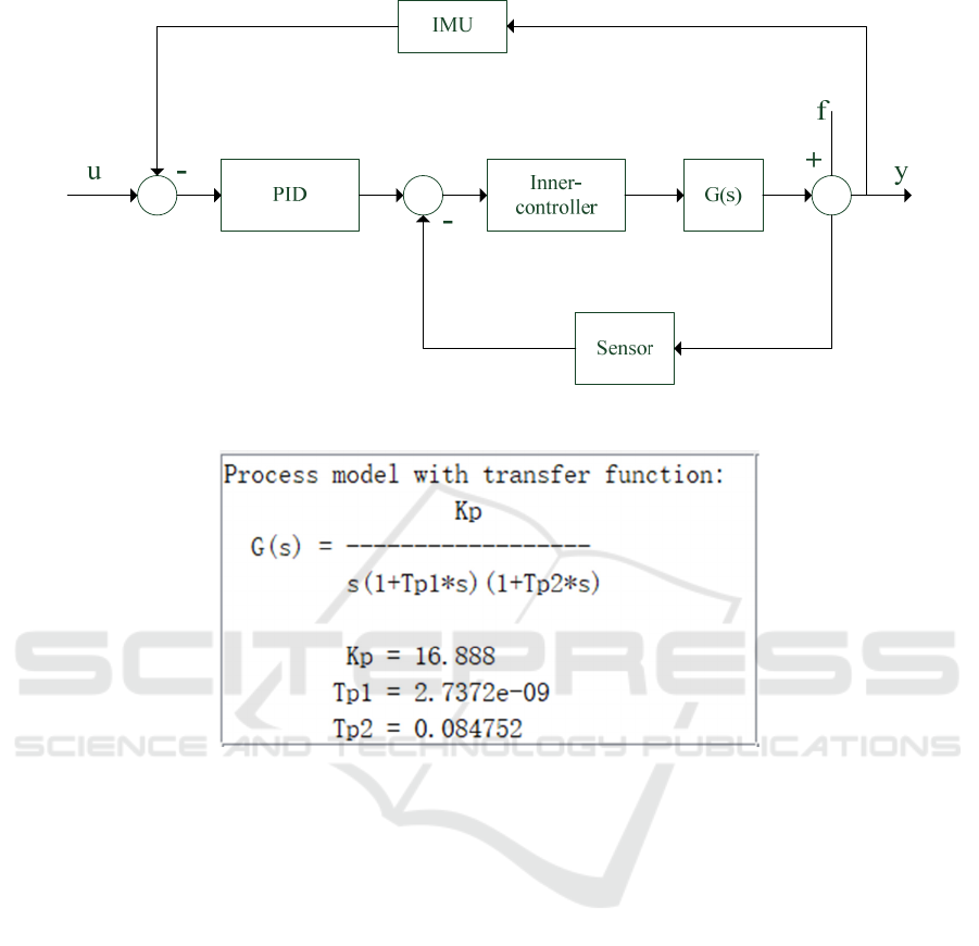
Figure 1. Dual-loop control structure.
Figure 2. Loaded motor transfer function identification result.
2.2
Design of Attitude Control Loop
The design method of the attitude control loop
controller is similar to the design method of the
frame angle control loop. The frame angle control
loop is regarded as the controlled object, and the
output of the attitude control loop can isolate the
effect of the interference f through the design of the
controller, thereby maintaining the stable platform.
The orientation in the inertial space is unchanged.
The next chapter will focus on the principles of BP
neural network control and combine it with classic
PID.
3 THE CONTROL PRINCIPLE OF
BP NEURAL NETWORK
Neural network control does not require precise
mathematical models, easy parallel computing, good
at learning from input and output, and nonlinear
mapping capabilities. Combining it with PID control
can make up for the lack of PID control, making the
control of the stable platform more effective.
3.1
BP Neural Network Structure
Model
The learning method of the neural network means
that the information is transmitted from the input
layer to the output layer layer by layer. If the output
cannot reach the expected value, the error signal is
transmitted back in the reverse direction, and the
error signal is reduced by modifying the parameters
of each layer, and then the forward propagation of
information repeats the forward transmission of
information and the reverse transmission of errors
until the error is less than a given value. The main
purpose of neural networks is to minimize errors in
network output. This is the BP neural network
ICVMEE 2019 - 5th International Conference on Vehicle, Mechanical and Electrical Engineering
324
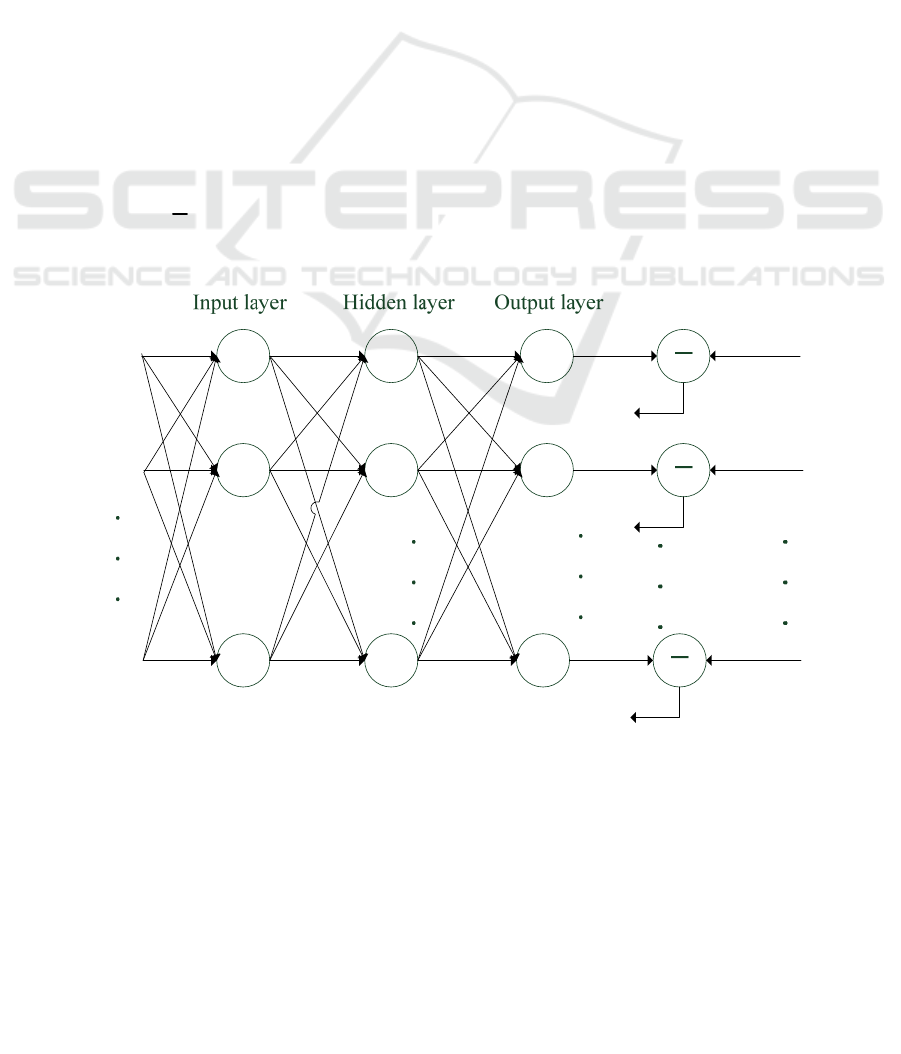
algorithm, and the three-layer neural network
structure is shown in Fig. 3.
1
x
,
2
x
,
…
,
n
x
is the input of thr network,
1
y
,
2
y
, …,
h
y
is the output of the hidden layer,
1
t
,
2
t
, …,
m
t
is the target output, the transfer function
of the input layer to the hidden layer is
f
, hidden
The transfer function from layer to output layer is
g
.
So you can get:
1
()
n
iiji
i
yf x
(1)
i
y
represents the output of the
j
th neuron of the
hidden layer. Output of the
k
th neuron of the output
layer:
1
()
h
kjki
j
zg y
(2)
At this point, the error between the actual output
and the target output is:
2
1
1
=( )
2
m
kk
k
tz
(3)
We call
() ()
f
xgx、
excitation functions, and
there are several types of commonly used excitation
functions:
Piecewise linear function, sigmoid function,
Gaussian function (Qing Zhang, Zhenfan Tan, Ying
Liang, 2008).
3.2 Neural Network PID
The control method obtained by combining the
neural network and the PID is the neural network
PID control (PIDNN). The control method has the
advantages of neural network and PID control, and
overcomes the shortcomings of the traditional PID
control in the nonlinear time-varying system. . The
structure of the PID control system based on BP
neural network is shown in Fig. 4.
The controller consists of two parts:
Classic PID control: closed control of the
controlled object directly.
BP neural network: the output state of the output
layer neurons corresponds to the three adjustable
parameters of the PID controller,
p
k
,
d
k
,
i
k
. The
self-learning and weighting coefficients of the neural
network are adjusted so that its steady state
corresponds to the PID controller parameters under
certain optimal control laws. Where is the transfer
function of the frame angle control loop (Peng
Meixiang, 2007).
Figure 3. Three-layer neural network structure.
1
x
2
x
n
x
1
y
2
y
h
y
1
z
2
z
m
z
1
t
2
t
m
t
1
2
m
ij
w
BP Neural Network PID Control of Stable Platform
325
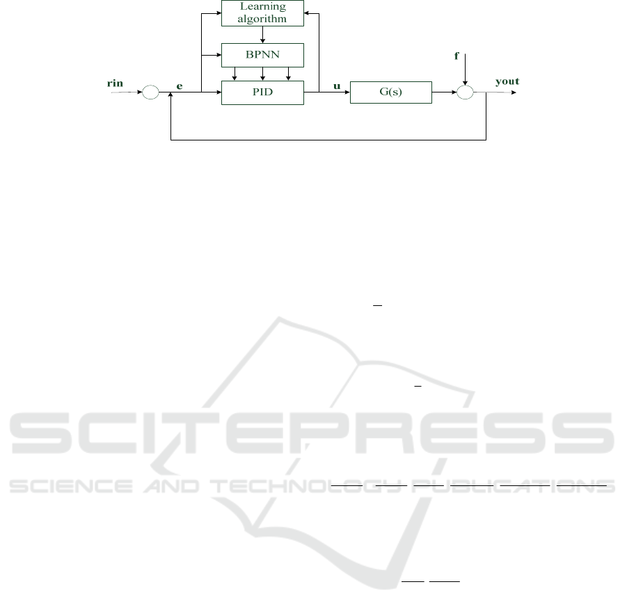
Figure 4. Control block diagram of stable platform based on BP neural network algorithm.
Let BP neural network NN be a three-layer BP
structure. It has m input nodes, q hidden nodes and 3
output nodes. The input node corresponds to the
operating state quantity of the selected system, and
the input quantity and output quantity at different
times as shown in the figure below are normalized if
necessary.
The output nodes correspond to the three
parameters of the PID controller
p
k
,
i
k
,
d
k
. Since
p
k
,
i
k
,
d
k
cannot be negative, the output layer
neuron activation function takes a non-negative
Sigmoid function.
The input of the BP neural network is
(1)
()
j
Oxj
, and
1, 2, ,
j
m
.
Where m is the number of input variables,
depending on the complexity of the controlled
system. The network hidden layer input and output
are respectively
(2) (2) (1)
0
()
m
iijj
j
net k o
(4)
(2) (2)
() ( ()) 1,2, ,
ii
Ok fnetk i q
(5)
In the formula(5),
(2)
ij
is hidden layer
weighting factor, the superscripts (1), (2), and (3)
represent the input layer, the hidden layer, and the
output layer.
Finally, the input and output of the three nodes of
the network output layer are:
(3) (3) (2)
0
() ()
q
llii
i
net k o k
(6)
(3) (3)
() ( ()) 1,2,3
ll
Ok gnetk l
(7)
In the formula,
(3)
li
is output layer weighting
factor.
Correcting the weight coefficient of the network
by the steepest descent method, that is, searching
and adjusting the negative gradient direction of the
weighting coefficient by
2
1
() ( () ())
2
Ek rink youtk
, and adding an inertial
term that makes the search quickly converge
globally, and then,
(3) 2 (3) (3)
1
() [ ( () ())]/ ( 1)
2
li li li
krinkyoutk k
(8)
is learning rate,
is inertia coefficient
(usually the value of
,
is between 0 and 1),while
(3) (3)
(3) (3) (3) (3)
() ()
() () () ()
() () () ()
ll
li l l li
Ok netk
Ek Ek yk uk
yk uk O k net k
(9)
In this way, the BP neural network output layer
weight calculation formula is:
(3) (3) (2) (3)
(3)
ˆ
() ()
() () '( ()) () ( 1)
(()
li l i li
l
yk uk
kek gnetkok k
uk o k
)
(10)
4 SIMULATION
Based on the previous sections, we analyzed the
design method of BP neural network PID controller.
The determination of BP neural network structure
and the selection of activation function are studied.
Below we design the angular control loop controller
as the controlled object of the attitude control loop,
and use the following parameters for simulation
analysis.
1. BP neural network structure selects 4-5-3
structure, the input vector is:
[ ( ), ( ), ( ),1]x rin k yout k error k
, the output vector is
[,,]
p
id
ykkk
;
ICVMEE 2019 - 5th International Conference on Vehicle, Mechanical and Electrical Engineering
326

(a)
(b)
Figure 5. BP Neural Network PID Control Structure.
(c)
Figure 6. Curve of parameter change.
BP Neural Network PID Control of Stable Platform
327

2. The activation function is selected as follows,
the activation function of the hidden layer selects the
hyperbolic tangent function:
()
x
x
x
x
ee
fx
ee
(11)
3. The activation os the output layer selects the
function:
()
x
x
x
e
gx
ee
(12)
4. Learning rate
0.16xite
;inertia factor
0.10alfa
; sampling time is 0. 005s.
The attitude control loop adopts BP neural
network controller and classical PID controller
respectively, and the sinusoidal response curve of
the stable platform with sinusoidal signal input with
amplitude of 0. 5V and frequency of 1Hz is shown
in the Fig. 5(a).
The tracking error curve of the stable platform is
shown in the Fig. 5(b).
The trend of
,,
p
id
kkk
is as shown in Fig. 6.
Taking the pitch axis as an example, can be seen
from the image obtained from the above simulation,
the control system adopts classical PID control
method, the input signal is a 1Hz sinusoidal signal.
Using FFT spectrum analysis to obtain sinusoidal
tracking error, the amplitude error is 5. 48% and the
phase error is 2. 1. The control system adopts BP
neural network PID control method, Using FFT
spectrum analysis to obtain sinusoidal tracking error,
the amplitude error is reduced to 3. 92% and the
phase error is reduced to 1. 8, meet the requirements
of the double ten indicator.
REFERENCES
Deng K, Cong S, Shen H. Control strategies and error
compensation methods of high precision gyro
stabilized platform [J]. Blood, 2011, 117 (6): 3450.
3455.
Peng Meixiang. BP neural network PID control [D]. East
China Normal University, 2007.
Qing Zhang, Zhenfan Tan, Ying Liang. Gyro Stabilized
System Based on Auto-Disturbance Rejection
Controller. IEEE Computing, Communication, Control,
and Management. 2008:2564-2431.
Wang Z S, Nian li LU, the Gyrobondgraph Method for the
Complete Dynamic Problem of Flexible Planar
Linkage Systems in Non. Inertial Coordinate System
[J]. Technology HIO, et al, 2005.
ICVMEE 2019 - 5th International Conference on Vehicle, Mechanical and Electrical Engineering
328
