
Design of Traffic Light based on FPGA
Xiaomin Han
1, a
, Shuzhen Huang
1
, Xiaohong Wang
1
, Yuying Ma
1
1
Shandong Vocational and Technical University of Engineering, Jinan 250200, China
Keywords: VHDL; traffic light; FPGA.
Abstract: This paper uses Altera's 5CSEMA5F31C6N chip to realize the hardware circuit description of the traffic
light system controller through VHDL language. It is compiled, simulated and downloaded to the FPGA
device for programming in Altera's EDA software platform Quartusii environment. The control process of
the traffic light system.
1 INTRODUCTION
With the increase of vehicles, traffic travel has
become a concern of everyone. Good traffic light
design can alleviate traffic pressure and ensure good
traffic order. This paper uses FPGA-based DE1-
SOC development board to simulate the intersection
traffic light. In addition to the basic traffic function,
the system also has a countdown function, which
simulates the actual traffic intersection. Provide a
theoretical basis for the actual traffic intersection.
Advantages of adopting VHDL language: (1)
powerful and flexible design; (2) modular and easy
to install; (3) reliable and easy to modify.
2 TRAFFIC SIGNAL CONTROL
TASKS
The intersection traffic light designed in this paper
has the function of indicating the opening and
stopping. Red, green and yellow signal lights and
digital tube displays are installed at each entrance.
Traffic rules: When the east-west direction is
open, when the north-south direction is forbidden,
the green light in the east-west direction is bright for
39 seconds, then the yellow light is on for 4 seconds,
the red light is bright, and the south-south direction
is red for 43 seconds, and the green light is bright.
When the north-south direction is open, when the
east-west direction is prohibited, the green light in
the north-south direction is bright for 20 seconds,
then the yellow light is on for 4 seconds, the red
light is bright, the east-west direction is red light for
24 seconds, and the green light is bright. Loop in
turn.
There is a set of countdown monitors in both the
east and west directions to show the passage time
and the forbidden time.
3 OVERALL DESIGN
This design is based on FPGA to complete the traffic
light control system. The 5CSEMA5F31C6N is used
as the core controller of the control system. The
three design entities are used to implement the
traffic light design in VHDL language, including:
crossover design entity, traffic signal light and
digital tube display circuit design entity, top-level
design entity (Qing Zhang, Xiaoping Cao, 2017).
4 DESIGN OF VARIOUS PARTS
OF THE SYSTEM
4.1 Frequency Division Circuit Design
The frequency of the DE1-SOC development board
is 50MHZ. This design requires 1HZ frequency, so
the process design and if...else statement are used to
complete the crossover design (Rundong Bi, Bo Gao,
2016). The schematic diagram module is shown in
Fig.1:
306
Han, X., Huang, S., Wang, X. and Ma, Y.
Design of Traffic Light based on FPGA.
DOI: 10.5220/0008386103060309
In Proceedings of 5th International Conference on Vehicle, Mechanical and Electrical Engineering (ICVMEE 2019), pages 306-309
ISBN: 978-989-758-412-1
Copyright
c
2020 by SCITEPRESS – Science and Technology Publications, Lda. All rights reserved
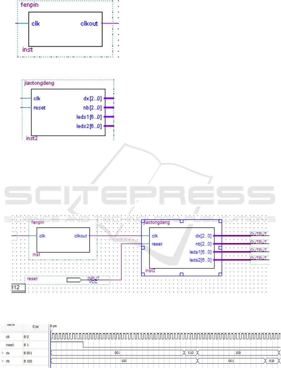
Fig 1. Frequency division circuit module.
Fig 2. Control circuit module.
4.2 Traffic Signal and Digital Tube
Display Circuit Design - Control
Circuit
This design uses LEDs as signal lights. The lamp is
turned on and off by means of the
5CSEMA5F31C6N chip. The digital tube uses a
seven-segment digital tube with a common anode. A
total of four digital tubes are used, two of which are
used for the display of the countdown of the east and
west roads, and the other two are used for the
display of the countdown of the north and south
roads. Using state machine to complete the signal
light off and digital tube counting design, it can be
divided into 4 states, namely: east and west green
light, north and south red light (S1); east and west
yellow light, north and south red light (S2); east and
west red light, north and south Green light (S3); red
light, north and south yellow light (S4). Program
design idea: first design a 68-ary addition counter,
and then design the 39-digit, 4-ary, 20-digit
subtraction counter to achieve the display count of
the digital tube; at the same time, complete the
design of the signal light on and off in each state (Bo
Li, Mengdi Yang, Xinxin Wang, 2019). The
generated schematic module is shown in Fig2.
4.3 Top Design
The top-level entity is formed by the frequency
dividing circuit and the control circuit, and the top-
level schematic diagram is shown in Fig3 (Zheming
He, Shen Yuan, et al, 2019).
Fig 3. Top-level entity.
The partial simulation circuit diagram is shown in Fig4.
Fig 4. Partial simulation circuit.
Design of Traffic Light based on FPGA
307
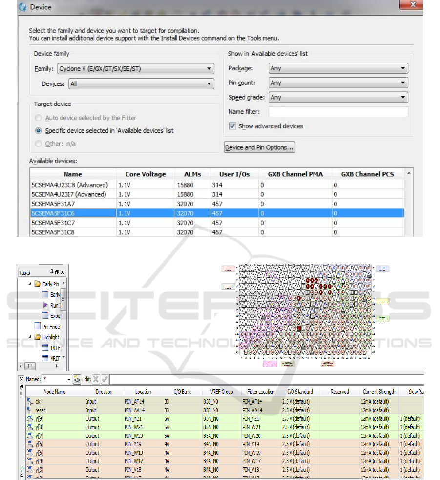
Fig 5. Device selection.
Fig 6. Pin binding.
5. PROGRAMMING TEST AND
RESULT ANALYSIS
5.1 Device Selection
Select the CycloneV Series 5CSEMA5F31C6N chip
is shown in Fig.5.
5.2 Pin Binding
Pin binding is shown in Fig.6.
5.3 Analysis of Results
After the circuit is connected, the written test
program is downloaded to the chip for testing. It is
ICVMEE 2019 - 5th International Conference on Vehicle, Mechanical and Electrical Engineering
308

observed that the display state of a small lamp and
the digital tube display meet the task requirements,
indicating that the design has no problem.
6 SUMMARY
The FPGA-based traffic light design proposed in this
paper has the advantages of easy implementation,
convenient modification and stability. Compared
with the traditional MCU-based traffic light control
system, this design has a broader development
prospect.
REFERENCES
Bo Li, Mengdi Yang, Xinxin Wang, Design of Traffic
Light Control System Based on EDA Technology.
Hebei Agricultural Machinery, 2019, (05), 41-42.
Qing Zhang, Xiaoping Cao, Design of Intelligent Traffic
Signal Controller Based on FPGA. Shandong
Industrial Technology. 2017, (16), 141.
Rundong Bi, Bo Gao,Design of Traffic Signal Control
System Based on FPGA. Chinese Journal of Electron
Devices.2016, 39 (01), 229-234.
Zheming He, Shen Yuan, et al. Design of Traffic Control
Light Based on FPGA. Computer Knowledge and
Technology.2019, 15(07), 239-239+257.
Design of Traffic Light based on FPGA
309
