
Design of Shipborne Radar Turntable Servo System
Chao Zhao
a
, Jiaguo Liu
b
and Yu Tang
c
Beijing Institute of Environmental Features, Beijing 100854,China
Keywords: Servo Turntable; Triple Closed Loop; PID Control.
Abstract: In view of the high attitude stability requirements of shipborne radar turret under sea conditions, the
hardware and software of the two-axis shipborne radar turret servo control system were designed.DSP chip
TMS320F2812 and FPGA chip were used as the servo control core for controller design, and Copley motor
drivers were used to drive the motors. The control software used the "current + speed + position" triple
closed loop control method and PID control algorithm was developed with CCS3.3 development platform.
The system triple closed loop control model was established and simulated with the Simulink module of
Matlab, and the result of 30 ms response time of the system was derived. Finally, the experimental
verification shows that the design of shipborne radar turntable servo control system meets the design
specifications.
1 PREFACE
The ocean is an important battlefield for the current
global power game, and the number and
advancement of warships are concentrated
expression of its competitiveness. Shipborne radar
plays an important role in target detection and early
warning. The warship is generally equipped with
high-precision shipborne radar. The radar antenna is
installed on the servo turret, and the sway of the hull
is isolated by the movement of the turret, so that the
radar antenna obtains stable relative inertia space,
and the target is searched, positioned and tracked
under the control command. The servo control
system is an important part of modern shipborne
radar, and its performance directly affects the radar
detection and tracking accuracy (Wang Yuqian, Gu
Weijie and Li Guiqiu, 2017).
Ji Wei, from Southeast University, conducted
theoretical research and experimental verification on
the techniques of visual axis stability control and
search tracking in the gyro stabilized photoelectric
tracking system (Ji Wei, 2006). Xu Tao, from
Changchun Institute of Optics and Mechanics,
Chinese Academy of Sciences, proposed an initial
calibration method for target tracking turntable
based on coordinate transformation, which is used to
improve the tracking accuracy of the moving base
photoelectric tracking system (Xu Tao and Li Bo,
2013). Ji Dong, from Aerospace Science and
Technology Second Research Institute, adopted a
method of adding disturbance observers on the gyro
speed loop to reduce the speed deviation caused by
the frictional interference of the turret and the carrier
disturbance, ensuring the stability of the stable
platform speed (Ji Dong, 2013).
2 SYSTEM BASIC
COMPOSITION AND
WORKING PRINCIPLE
The turntable servo control system is mainly
composed of mechanical structure, servo controller,
driver, servo motor, detection component, and
display control (Liu Sheng, Peng Xiafu and Ye
Guizhen, 2001). The shipborne radar turret is a two-
axis servo turret, azimuth axis and pitch axis. The
servo control loop consists of two independent
control systems, the azimuth control system and the
pitch control system. The basic composition of the
turret is shown in Fig.1.
Zhao, C., Liu, J. and Tang, Y.
Design of Shipborne Radar Turntable Servo System.
DOI: 10.5220/0008385802990305
In Proceedings of 5th International Conference on Vehicle, Mechanical and Electrical Engineering (ICVMEE 2019), pages 299-305
ISBN: 978-989-758-412-1
Copyright
c
2020 by SCITEPRESS – Science and Technology Publications, Lda. All rights reserved
299
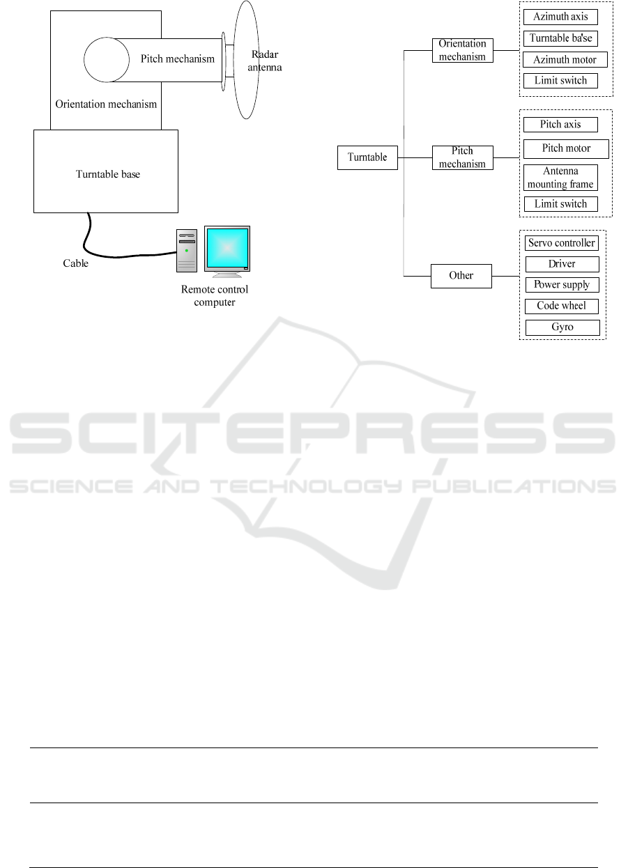
Figure 1. Block diagram of the stable platform.
The two-axis shipborne turntable controller
controls the motion state of the servo motor by
receiving the off-target amount transmitted by the
host computer and the feedback signals of the code
wheel and the gyro to realize the search and tracking
function of the target Zheng Yanwen, Wang Yuyu,
Lin Lin, Huang Yuxin, Fan Genxin, 2013). In this
design, the radar needs to detect and locate the air
target, and the positioning accuracy of the turntable
is high. The performance requirements of the
turntable are shown in Table 1.
3 SERVO SYSTEM DESIGN
The azimuth control system is composed of a servo
controller, a driver, a servo motor, a code wheel and
a gyro. The pitch control system is composed of a
servo controller, a driver, a servo motor, a code
wheel, a gyro, and a limit switch. The overall block
diagram of the servo system is shown in Fig.2.
Figure 2. Overall block diagram of the servo system.
3.1 Servo Controller Design
The controller is based on DSP and FPGA chips.
The main functions of the servo controller include
control algorithm, signal acquisition, communication
with the terminal, and control of peripheral devices.
The DSP uses TI's TMS320F2812 with a clock
frequency of 150 MHz, an on-chip 128K×16 Flash,
integrated the motor control peripheral event
manager (EVA and EVB), serial communication
peripherals and a 12-bit 16-channel ADC with 56
general purpose I/O (GPIO). In order to achieve
high-precision control, the 12-bit ADC of DSP is
used as a backup. The 16-bit AD7656 is selected as
the sampling AD to collect the gyro signal. The 16-
bit DAC7744 is selected as the DA output to control
the Copley controller to drive the servo motor. The
servo control circuit diagram is shown in the Fig.3.
Table 1. Shipborne radar turntable performance indicators.
Structure
Type
Rotation Range
/ ()
Range of Rotation
-1
/s(( ) )
Maximum Angular
Acceleration
-2
/s(( ) )
Positioning
Accuracy
/ ()
Azimuth
Axis
0~360 0.1~25 30 0.02
Pitch
Axis
-10~100 0.1~20 30 0.02
ICVMEE 2019 - 5th International Conference on Vehicle, Mechanical and Electrical Engineering
300
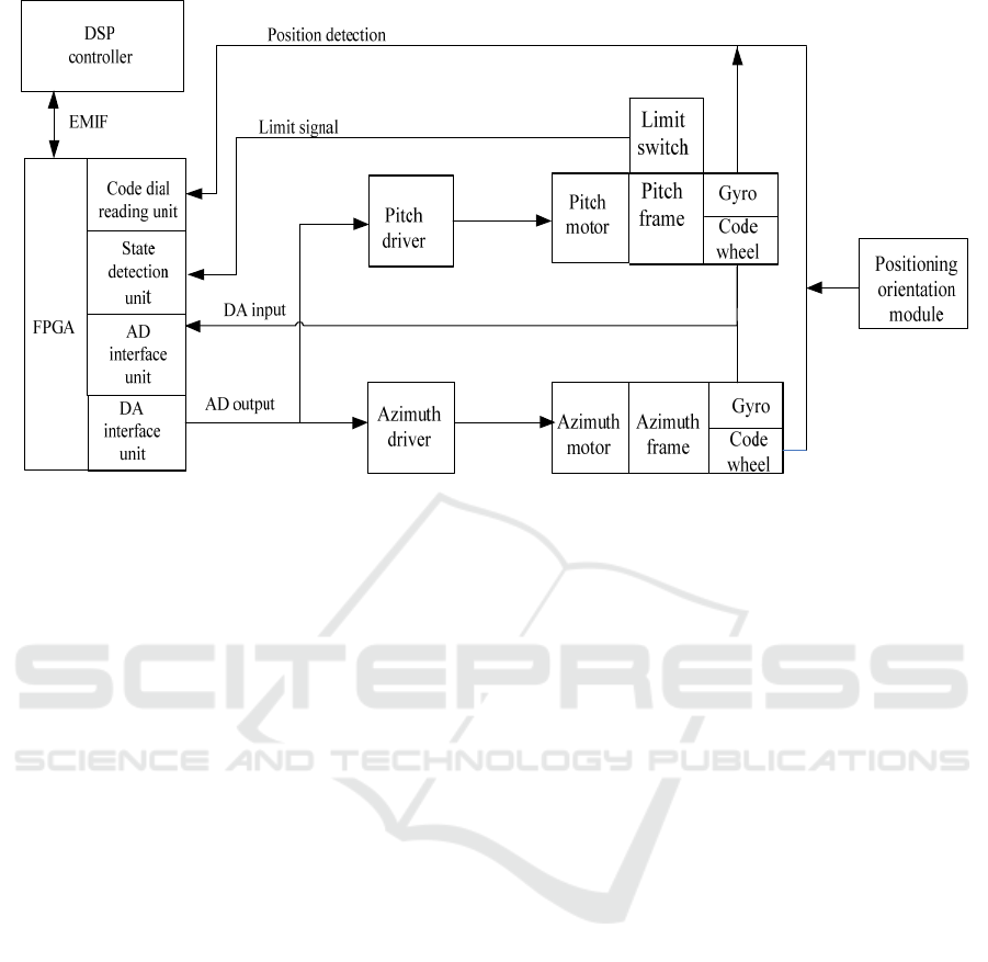
Figure 3. Schematic diagram of servo control circuit.
The servo controller sends the generated control
quantity to the driver through the DA port, and the
driver power-amplifies the signal to drive the servo
motor to drive the platform to perform
corresponding motion. The photoelectric encoder is
installed as the speed sensor and the position sensor
at the end of the platform swing mechanism. The
gyro measurement base motion information is
installed on the platform base. The positioning
orientation system is installed to obtain the angle
information of the stable platform in the inertial
space, and the limit function is realized by the
photoelectric switch.
3.2 Servo Drver Selection
The servo drive is one of the cores of the servo
control. Copley's industrial servo driver is selected.
The analog signal output from DA is transmitted as a
control command to the Copley servo driver, and the
position information and speed information returned
by the drive are accepted. The main interface is the
motor control interface, RS232 communication
interface, CAN communication interface, dual
encoder interface, 9 IO input interface, 4 IO output
interface, and its characteristics are as follows:
1) It has a dual encoder interface (motor encoder
interface and load encoder interface);
2)The drive control system adopts triple closed
loop structure (current loop, speed loop and position
loop), each closed-loop system parameter can be set,
and the maximum value of the parameter can be
limited to facilitate safe debugging;
3) It has strong environmental adaptability, and
the working environment temperature is -25 °C ~ 70
°C.
3.3 Servo Control Software Design
The software design of the controller mainly
includes the communication software of the upper
computer and the control software of the lower
computer (Wu Tianzhu, 2010). In this study, the PID
control algorithm is used to realize the “current+
speed+ position” triple closed loop control, so that
the response speed and tracking accuracy of the
turntable control system meet the performance
requirements.
The servo control software is based on DSP
system development, and the development tool
software is CCS3.3. The main program mainly
includes two parts of initialization and loop running
program. The initialization includes hardware and
system initialization and servo running environment
initialization. The main flow chart of the servo
control program is shown in Fig.4. It mainly
includes the main function modules such as serial
communication module, motor control module and
servo control module.
Design of Shipborne Radar Turntable Servo System
301
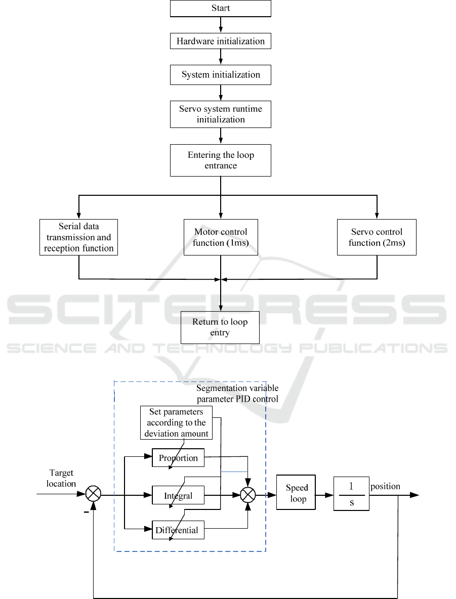
Figure 4. Servo control software main program flow char.
o
i
Figure 5. Schematic diagram of segmentation variable parameter PID control.
ICVMEE 2019 - 5th International Conference on Vehicle, Mechanical and Electrical Engineering
302
3.4 Code Disk Position Loop Control
Strategy Design
The position and position control adopts the
segmentation variable parameter PID control
algorithm in Fig. 5, which has the advantages of
simple algorithm, good robustness, and the ability to
balance both fast performance and stability
performance.
In order to achieve precise positioning of the
turntable, a segmentation variable parameter PID
control algorithm is adopted in the positioning
control, and the error is divided into three segments
according to different sizes of position errors during
positioning.
(1) When
1
ek
, the P controller is used at
this time,
1pp
K
k
, so that the response time of the
system is faster and the overshoot is small.
(2) When
21
ek
, use the PD
controller,
2pp
K
k
,
ii2
Kk
, to speed up the
system adjustment speed, shorten the system
adjustment time, and reduce the steady state error.
(3) When
2
ek
, use PID controller,
3pp
K
k
,
3ii
Kk
,
3dd
Kk
,to improve the
overall control accuracy of the system.
Among them,
123
0
pp p
kkk
,
23
0
ii
kk
,
3
0
d
k
.
4 SYSTEM SIMULATION AND
ANALYSIS
In order to facilitate the analysis of the relevant
performance of the shipborne servo radar turntable
control system, the motor model and the three closed
loop control model of the azimuth axis are
established, and the model is simulated and
analyzed.
4.1 Motor Model
According to the selected servo motor, driver
parameters and the magnitude of the received
torque, the transfer function of the azimuth motor
current and angular velocity is:
1
(s)
0.0015 10
i
G
s
(1)
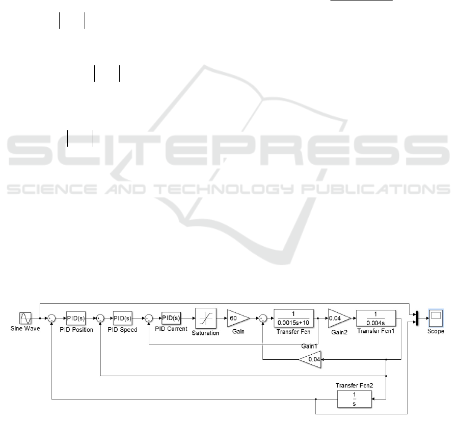
4.2 Triple Closed Loop Control Model
Simulation
The step response model of "current + speed +
position" triple closed loops and the sinusoidal
signal tracking curve are established in the Simulink
module of Matlab software. The sinusoidal signal
tracking simulink simulation model is shown in Fig.
6.
Set the input signal to a sinusoidal signal with a
magnitude of 1
, a frequency of 0.5 Hz, and a
simulation time of 6 s. The sinusoidal signal tracking
curve of the system can be obtained through
simulation, and the sinusoidal signal tracking curve
is shown in Fig. 7. According to the image display,
the system tracking performance is good.
Set the input step signal to 1
/s
, and perform
mathematical simulation on the system. The step
response diagram is shown in Fig.8. It can be seen
that the speed loop response time is 30 ms, the rise
time is 3 ms, the peak time is 6 ms, the transition
time is 25 ms, and the overshoot is 2.25%.
Figure 6. Sinusoidal signal tracking simulink simulation model
Design of Shipborne Radar Turntable Servo System
303
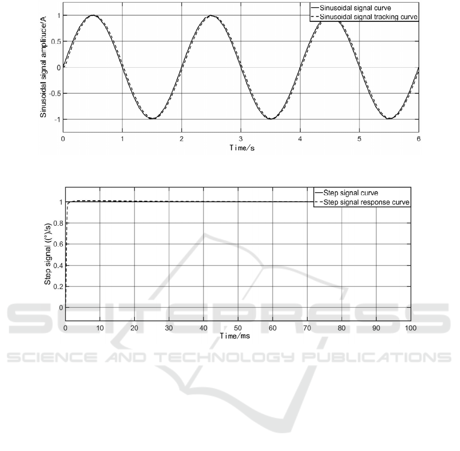
Figure 7. Sinusoidal signal tracking curve
Figure 8. Step signal response curve.
5 CONCLUSION
This paper introduces the hardware and software
design of the shipborne radar servo turntable control
system, adopts the "current + speed + position" triple
closed-loop control mode, and uses the
"TMS320F2812+FPGA" chip as the servo control
core to design the controller through Copley. The
selection of the motor driver realizes the driving of
the motor; through the segmentation variable
parameter PID control algorithm, the high-precision
positioning requirements of the shipborne radar
turntable are realized, and the relevant control
software design is carried out by using the CCS3.3
development platform.
The mathematical model of the servo system of
the turntable is established. In the simulink module
of Matlab, the three-closed control model of the
system is simulated mathematically, and the
response time of the step signal of the system is 30
ms. by simulating the tracking of the sinusoidal
signal, the tracking performance of the system is
verified.
At the same time, the relevant indicators are
verified through experiments, and the actual
indicators meet the requirements of the design
indicators.
REFERENCES
Ji Wei, “Research on servo control system of gyro
stabilized photoelectric tracking platform,” Ph.D.
thesis, Southeast University, 2006.
Ji Dong, “Design of the Vehicular Eletro-optical Tracking
Turntable Servo System and the Research on its
Tracking Control sheme, ”Advances in Manufacturing
Science and Engineering, PTS 1-4.2013, pp.2119-
2123.
Liu Sheng, Peng Xiafu and Ye Guizhen, Modern servo
system design, (Harbin Engineering University Press,
Harbin, 2001), pp.33-34.
Wang Yuqian, Gu Weijie and Li Guiqiu, “Study on Servo
Control System of Shipborne Radar Two-Axis
ICVMEE 2019 - 5th International Conference on Vehicle, Mechanical and Electrical Engineering
304

Turntable Based on Fuzzy Sliding Mode Variable
Structure,” Inverter World, 2017(11), pp93-96.
Wu Tianzhu, “Design of servo control system based on
DSP turntable,” Ph.D. thesis, Harbin Engineering
University, 2010.
Xu Tao and Li Bo, “Initial calibration of tracking turntable
in vehicle photoelectric tracking system”, Optics and
Precision Engineering, 2013, 21(03), pp. 782-789.
Zheng Yanwen, Wang Yuyu, Lin Lin, Huang Yuxin, Fan
Genxin, “Design of Two-axis Turntable Servo Control
System Based on DSP, ”Mechanical & Electrical
Engineering,2013,(2),pp.210-213.
Design of Shipborne Radar Turntable Servo System
305
