
Design of a Small-sized Simple Printed Circuit Board Engraving
Machine
Kai Zheng
1, a
, Jiangping Nan
2, b
1
Department of Electrical Engineering, Xi’an Traffic engineering Institute, Xian city, Shaanxi Province, China
2
Department of Electrical Engineering, Xi’an Traffic engineering Institute, Xian city, Shaanxi Province, China
Keywords: Table engraving machine, machine design, control system.
Abstract: What this design has developed is kind of simple PCB CNC engraving machine for personal and school
laboratories (hereinafter referred to as: engraving machine). According to the requirement of system design,
the design scheme of main motion and feed motion of engraving machine is fully demonstrated. The system
consists of mechanical part and control part. The mechanical part adopts vertical structure and calculates the
design parameters according to the working requirements of the system. The control part takes PC as the
control core to design the control hardware module. The open-loop servo system with simple structure,
stable operation, easy control and convenient maintenance is adopted.
1 INTRODUCTION
With the rapid development of computer technology,
the engraving machine system which combines CNC
technology with traditional engraving machine has
been widely used. However, no matter foreign or
domestic CNC engraving machine systems, a large
part of them are dedicated apparatus, which are
expensive and not easy to maintain, to a certain
extent, hindering the development of engraving
technology (
Chen Jianning, J., 2016). For the sake of
meeting the demands of the market product line, we
have developed a small-sized and simple printed
circuit board engraving machine based on the
support of Mach3 software and computer platform.
2 OVERALL DESIGN SCHEME
OF ECONOMICAL TABLE
ENGRAVING MACHINE
2.1 The Design Objective of the
Engraving Machine
At present, printed circuit board (PCB) is mainly
processed by chemical etching method in practical
processing. Processing with traditional chemical
etching method not only increases labor intensity,
but also complicates the processing technology. The
processing efficiency cannot be guaranteed and the
environmental pollution and material loss are greater.
Therefore, a new processing method and equipment
are needed.
During the past half century, the PCB
manufacturing industry has been developing
continuously from small to large, from low to high
level, especially the development of household
appliances in the 1980s and the boost of information
industry in the 1990s, which has greatly pushed
forward the development of the entire PCB industry.
The manufacture of PCB has been is becoming more
and more miniaturized, refined and diversified. For
the sake of meeting the development of the market
and the high-end demand, the engraving machine
should not only meet the manufacturing
requirements of the engraving machine, but also
simplify the mechanical structure on the premise of
improving the economy. Computer parallel port
communication technology and control software are
used to design and manufacture an economical table
engraving machine with simple mechanism, high
precision, easy control and convenient maintenance.
2.2 Composition of Control System of
Engraving Machine
The main control module of this system adopts the
mainstream mode of PC + control software; The
288
Zheng, K. and Nan, J.
Design of a Small-sized Simple Printed Circuit Board Engraving Machine.
DOI: 10.5220/0008385402880292
In Proceedings of 5th International Conference on Vehicle, Mechanical and Electrical Engineering (ICVMEE 2019), pages 288-292
ISBN: 978-989-758-412-1
Copyright
c
2020 by SCITEPRESS – Science and Technology Publications, Lda. All rights reserved
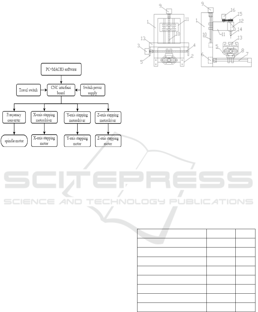
feed system adopts the combination of stepping
motor and driver to drive the motion of each axis
(
Fan Chaoyi, Fan Wei, J, 2018); The spindle motor
adopts DC motor and the most widely used PWM
pulse width modulation technology to realize the
drive and speed regulation of spindle motor; In
addition, it also includes power module and
auxiliary module of engraving machine. The control
system schematic diagram is shown as Figure 1.
Figure 1. Control system schematic diagram.
2.3 Composition of Mechanical System
of Engraving Machine
This item consists of post, base, spindle, worktable
and X, Y, Z three-axis executive parts, each
executive part includes (stepping motor, ball screw,
sliding plate). The correlations between them are
that there are post above the base, Z-axis executive
part on the post, and spindle, pulley mechanism and
electric motor on the Z-axis sliding plate. A cross
sliding platform consisting of X-axis and Y-axis
executive parts is installed above the bottom plate.
The outer ends of X-axis, Y-axis and Z-axis ball
screws are respectively connected with X-axis, Y-
axis and Z-axis stepping motors through coupling.
The engraving tool is installed on the spindle, a
worktable is arranged below it, and the worktable is
installed on the X-axis sliding plate. The mentioned
spindle adopts a unpowered spindle, which can be
connected with an electric motor through a pulley
mechanism to provide power for the spindle's
rotational motion.This vertical structure ensures the
requirements of simple structure, low cost, easy
processing and assembly of the engraving
machine.The mechanical structure of the system is
shown as Figure 2.
Figure 2. System mechanical structure.
1-post, 2-base, 3, 6, 9-stepping motor, 4, 7, 10-
Screw rods of each axis, 5, 8, 11-sliding plates of
each axis, 12-unpowered spindle, 13-work table, 14-
tool, 15-Pulley mechanism, 16-Electric motor
3 OVERALL DESIGN SCHEME
OF ECONOMICAL TABLE
ENGRAVING MACHINE
3.1 Design Parameters of Engraving
Machine
According to the requirement of the working scene
of the engraving machine, the design indicators of
the engraving machine is worked out. Specific
indicators are shown as Table 1.
Table 1. Design indicator parameter table of engraving
machine.
Item Parameter Unit
Spindle maximum speed 24000 r/min
Maximum feed speed 3000 mm/min
X-axis travel 200 mm
Y-axis travel 260 mm
Z-axis travel 70 mm
positioning accuracy 0.05 mm
Pulse equivalent 0.01 mm
Service life 15000 hrs
3.2 The Technical Scheme of
Engraving Machine Design
For the sake of the design of a kind of small-sized
and simple printed circuit board engraving machine
(hereinafter referred to as: engraving machine),
Design of a Small-sized Simple Printed Circuit Board Engraving Machine
289
adopting synthetic approach, according to the
relevant knowledge provided by a large number of
documents, refer to the data and learn the relevant
specific knowledge, analyze and design the overall
structure of the engraving machine and specific
functional modules. The technical route of this
article is shown as Figure 3.
(1)Refer to the literature, induce and summarize
the shortages of existing PCB processing modes.
(2)Propose improvement plan for the existing
PCB processing methods, such as chemical
corrosion, environmental pollution, low efficiency,
etc.
(3)According to the improvement scheme, find
out the difficulties and key points in the scheme, and
select the relevant technology to master.
(4)On the basis of mastering relevant
technologies (such as PLC technology, CAD
technology, communication interface technology,
etc.), combine theory with practice, put forward
solutions to improve the difficulties and key points.
(5)According to the scheme, carry out the
hardware structure design of the engraving machine.
(6)According to the scheme, carry control system
design of engraving machine.
(7)Build a prototype machine on the basis of
item 5 and 6.
(8)The reliability and feasibility of the physical
model are tested and continuously improved until
the expected results are achieved.
(9)Summarize project experience and write
papers.
3.3 The Scheme Design of the Motion
Control System of the Engraving
Machine
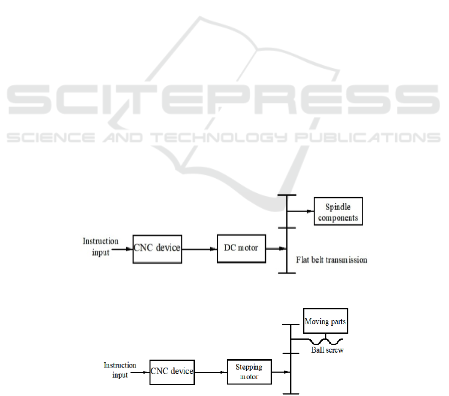
Compared with the main transmission system of
common machine tools, the spindle system of a
small and simple PCB engraving machine has light
load and small volume, so the spindle system of an
economical table engraving machine has simpler
structure and easier operation. There are usually two
kinds of spindle motion schemes: One is to use a
special engraving head. When using this engraving
head, it needs to be equipped with frequency
conversion speed regulating device, which greatly
increases the manufacturing cost. The other is to use
DC motor to drive the spindle directly. The accuracy
of this method is low, but the DC motor is cheap.
For individuals and small and medium-sized users
who do not require high accuracy and speed, the
cost-effective scheme of DC motor driving the
spindle is higher. The composition principle of the
main motion scheme is shown as Figure 3.
3.4 Design of Feed Motion Scheme of
Engraving Machine
According to the working requirement, the table
engraving machine adopts open-loop CNC system.
The design of the transmission part utilizes the
working principle of the stepping motor to control
(
Pan Songguang, D., 2014) the screw drive. After the
pulse signal sent by the CNC device is amplified by
power, it drives the stepping motor to rotate a step
angle and drives the screw nut pair to rotate to drive
the axial displacement. The composition principle of
feed motion scheme is shown as Figure 4.
Figure 3. The composition principle of the main motion scheme.
Figure 4. Composition principle of feed motion.
ICVMEE 2019 - 5th International Conference on Vehicle, Mechanical and Electrical Engineering
290
3.4.1 Selection of Motor
In small and medium servo systems controlled by
open-loop, stepping motor and reducer transmission
ratio can be used to calculate.
1.5 5
2
360 360 0.01
p
p
i
(1)
The number of teeth of each transmission gear
isrespectively, Z1=20, Z1=40, Modulem=2mm,
Breadth of tooth b=20mm. Big gear is adjusted by
staggered teeth of double cylindrical thin-section
gear.
Calculation of total equivalent load moment of
inertia on motor axis.
m
j
=
3
0.617 10
2
kg m
(2)
34
2
1
7.8 10 0.04 0.02
32
z
jkgm
(3)
34
2
2
7.8 10 0.08 0.02
32
z
jkgm
(4)
The total equivalent load moment of inertia can
be obtained by converting the transmission inertia
and the mass of the worktable to the motor axis.
2
42
12
2
1
2.12 10
2
dz z
p
jj j m kgm
ii
(5)
Therefore, the 75BF001 stepping motor is
selected as the primary type.
3.4.2 Selection of Ball Screw
According to the dimension series of ball screw
pairs (ISO/DIS3408-2.1991) and the standard table
(Table 2) of GB/T 17587.2-1998, the 1204 ball
screw is selected according to the actual design.
Table 2. Dimension series of ball screw pairs.
Nominal
diameter series
mm
6, 8, 10, 12, 16, 20, 32,
50, 63, 100, 125, 200
Engineering lead
series
mm
1, 2, 2.5, 3, 4, 5, 6, 8,
10, 12, 16, 20, 25
Engineering lead
preferred series
mm 2.5, 5, 10, 20, 40
3.4.3 Coupling Original Selection
When the transmission ratio is i=1, the motor can be
directly connected to the lead screw by coupling. If
the worktable’s pulse equivalent
=0.01 mm/pulse,
According to the original selection screw
specification M12*4 in 2.4.2, the helical pitch is 4
mm.
Then based on transmission ratio formula
0
360
b
p
L
i
,we can obtain
0.9 4
1
360 0.01
i
So the motor can be directly connected with the
screw by coupling, and the clamping screw is
selected to fix the micro rigid coupling.
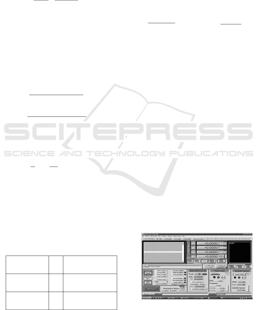
4 DESIGN OF CONTROL
SYSTEM OF ENGRAVING
MACHINE
The design of control system consists of three main
parts: control chip, spindle motor control scheme
and stepping motor drive. The system realizes the
communication between PC and engraving machine
through parallel port of computer. The obtained
processing object files are processed into G code by
control software and the corresponding frequency
and direction signals of processing characteristics
are sent. The drive scheme of spindle motor adopts
PWM pulse width modulation technology, which
can control the speed of DC motor by changing the
duty ratio of pulse sequence to change the output
voltage (
Zhang Xiao, D., 2013
).Stepping motor drivers
on three axes of engraving machine are all driven by
stepping motor drivers with TB6560 as driving chip,
which have the characteristics of high integration
and high reliability, etc (
Zhang Xiao, D., 2013
). The
control system software interface is shown as
Figure5.
Figure 5. Control system software interface.
Design of a Small-sized Simple Printed Circuit Board Engraving Machine
291

5 CONCLUSIONS
The engraving machine developed in this design is a
kind of small-sized and simple printed circuit board
engraving machine system. This system consists of
physical layer, mechanical body, hardware layer,
control circuit and software layer. The machine body
adopts a gantry mobile layout with simple structure
and high rigidity to ensure the reliability of machine
tool; Control system software based on PC
development realizes stepping motor driving carving
feed. DC motor and PWM speed regulating circuit
constitute the main motion system. It fully meets the
manufacturing requirements of simple structure,
stable operation, easy control and convenient
maintenance.
REFERENCES
Chen Jianning, J., 2016. Popular Science (science
education). In Popular Science (science
education)’186+128, 5th edition of 2016. Scientific
Popular (Science Education). Design of Economic
Desktop Engraving Machine System.
Fan Chaoyi, Fan Wei, J., 2018. In TEMPLATE’ 310-314,
Machine Tool and Hydraulic Pressure. Selection and
calculation of stepping motor.
Pan Songguang, D., 2014. Shandong University. Research
on Machine Tool Product Design Based on UCD.
Zhang Xiao, D., 2013. Nanjing Forestry Uni.
ICVMEE 2019 - 5th International Conference on Vehicle, Mechanical and Electrical Engineering
292
