
Autonomous Gripping and Carrying of Polyhedral Shaped Object based
on Plane Detection by a Quadruped Tracked Mobile Robot
Toyomi Fujita and Nobuatsu Aimi
Department of Electronics and Intelligent Systems, Tohoku Institute of Technology, Sendai 982-8577, Japan
Keywords:
Mobile Robot with Multiple Manipulation Arms, Autonomous Gripping, Depth Image, Plane Detection,
Observation Position Computation.
Abstract:
Recently, it is highly expected that robots work instead of human in a dangerous site such as disaster area.
Sufficient working ability is required for such robots as well as moving ability. Thus, we present a method for
autonomous gripping and carrying of a polyhedral shaped object by a mobile robot with multiple manipulation
arms based on plane detection. Using this method, the robot can calculate appropriate observation positions
for the detection of gripping planes and positions of the object. We apply the method to a quadruped tracked
robot and verify its effectiveness in experiments for autonomous gripping and carrying of a box shaped object.
1 INTRODUCTION
In recent years, a robot is expected to perform some
actions related to rescue activity in a disaster area.
The robot should perform not only an exploration but
also a working task by itself in the area. For such
a task, the robot that has manipulation arms is use-
ful. Therefore, we have developed several tracked
mobile robots that were equipped with multiple legs
which can be used as manipulation arms (Fujita and
Tsuchiya, 2014) (Fujita and Tsuchiya, 2015) (Fujita
and Sasaki, 2017). These robots can operate some
handling tasks such as a transportation of target ob-
ject using two legs by a remote control. However, it is
basically difficult to control properly for such tasks.
In order to solve this problem, this study consid-
ers that such robots perform transportation tasks au-
tonomously by detecting gripping positions of a poly-
hedral shaped object. Proposed method is based on
the detection of gripped planes by two manipulation
arms. In the method, the robot detects gripping planes
and positions using a depth sensor by observing the
object at several positions. We consider how to de-
termine proper observation positions to detect them
efficiently.
The following sections describe the overall
method for detecting information to grip and carry a
polyhedral shaped object in Section 3, how to deter-
mine the observation positions in Section 4, imple-
mented robot system in Section 5, and experiments
for proposed methods in Section 6.
2 RELATED WORKS
Recently, some autonomous planning for robot grip-
ping have been considered.
Yamazaki et al. presented a method for object
grasping by modeling based on voxel representation
(Yamazaki et al., 2007). In this method, a robot ob-
serves an object from multiple views and generates a
3-D model consisting of voxel. The gripping position
is determined by the area of voxel and posture of the
hand. It may be difficult for our aim to apply because
the robot needs to move the area surrounding object
to capture multi-viewpoint images.
Masuda and Lim presented a method for plane de-
tection utilizing 3-D Hough transform and a structure
of retina (Masuda and Lim, 2014). However, gripping
planning is not considered after the plane detection.
We present a method based on plane detection of
a polyhedral object and obtain planes on which the
robotic arms can grip and manipulate by their hands.
Gu et al. presented a grip planning method to gener-
ate optimal collision-free grip sequences for a biped
climbing robot based on a pole detection and grasp-
ing pose computation using depth and image data(Gu
et al., 2017)(Gu et al., 2018). This method mainly
considers point and line information as geometric in-
formation. This study, on the other hand, mainly con-
sider plane information of a polyhedral object.
In the method presented by Harada et al., the
shape of object was obtained as a cluster of triangle
planes using a map of normal vectors, then gripping
552
Fujita, T. and Aimi, N.
Autonomous Gripping and Carrying of Polyhedral Shaped Object based on Plane Detection by a Quadruped Tracked Mobile Robot.
DOI: 10.5220/0007980905520558
In Proceedings of the 16th International Conference on Informatics in Control, Automation and Robotics (ICINCO 2019), pages 552-558
ISBN: 978-989-758-380-3
Copyright
c
2019 by SCITEPRESS – Science and Technology Publications, Lda. All rights reserved
was performed by detecting the regions on the surface
of the object which can be contacted with the gripper
(Harada et al., 2011). Our method is based on sim-
ilar concept to this approach and is arranged for the
grasping by two robotic arms mounted on a mobile
robot.
3 OBJECT GRIPPING AND
CARRYING
3.1 Overview
In this study, we suppose that a user operates a mo-
bile robot with multiple manipulation arms by remote
control in general, finds a target object through im-
ages sent from the camera mounted on the robot, then
approaches the robot in front of the object. The robot
then starts autonomous object gripping and carrying
based on plane detection from that circumstance.
The proposed method is as follows. Firstly, the
plane information of the object is detected in the en-
vironment using a depth sensor. Secondly, sets of two
parallel planes that can be reached by the tips of two
manipulation arms are extracted so that the solutions
of inverse kinematics exist for the both arms. All pos-
sible combinations of the set are extracted as candi-
dates of gripping planes. In the inverse kinematics
computation, the robot positions as well as the pos-
tures of both manipulation arms are also computed.
The position of the robot to grip is selected from them
such that the movement of the robot from its position
at that time becomes minimum. With the gripping po-
sition of the robot, then the postures of the manipula-
tion arms are also determined. The robot then moves
the position, grips the two planes by two manipulation
arms, lifts up the object, and transports it.
This method can be used for a variety of the shape
and orientation of object because it is applicable re-
gardless to the number of plane of the object.
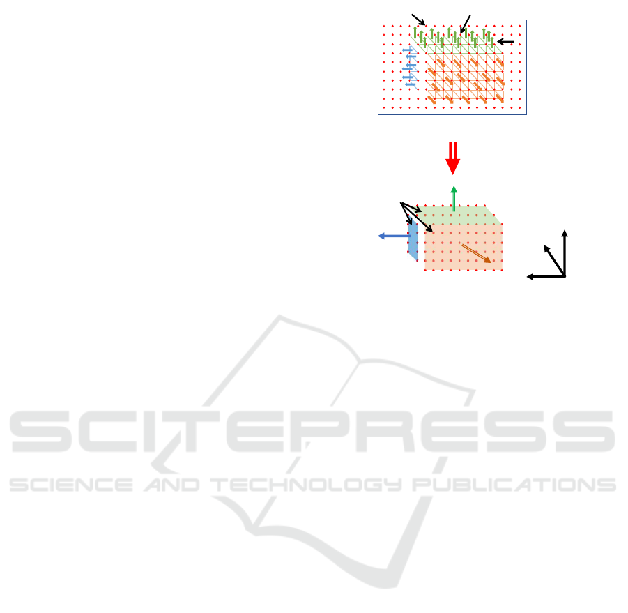
3.2 Plane Detection
In this study, we use a depth sensor to detect planes.
As a pixel of the depth image can make a 3-D small
plane with the next right and under pixels, all small
planes are extracted on the depth image. Then, adja-
cent small planes which have the same normal vector
are integrated as one plane. Figure 1 shows an exam-
ple of the plane integration. The upper panel shows
the small planes and their normal vectors extracted
from pixels of the depth image and the lower panel
shows the integrated planes.
Depth image
Search point
Obtained planes
Normal vector
Z
Y
X
Small planes
Integrated
planes
Normal vector
Figure 1: Generation and integration of small planes.
3.3 Gripping Position Detection
Gripping planes for two manipulation arms of the
robot are determined from detected planes. To do
that, sets of two planes which have the same or op-
posite directions of normal vector each other are ex-
tracted. The sets become candidates for gripping. In
this method, horizontal planes to the ground and small
planes, which may not be possible to be gripped, are
excluded from candidate sets of gripped planes for ef-
ficient processing.
The candidate sets are then checked for the possi-
bility of gripping by the left and right manipulation
arms using inverse kinematics. Figure 2 shows an
overview of this process. Let us assume an environ-
ment of flat ground and the robot moves on XY plane
for simplicity. The projection line AB on XY plane
is extracted by the line connecting two centers of the
candidate planes. Let f be the line on XY plane which
is orthogonal to the line AB and passing the center
point C of AB. We suppose that the robot places on a
position R on the line f in the same orientation of the
line. Inverse kinematics are computed for each R so
that the position of each tip of the left and right ma-
nipulators comes each center of the candidate planes
in the orientation of the line AB. If solutions of in-
verse kinematics exist for the both tips, these candi-
date planes can be gripped by the robot at the position.
The set of planes is therefore extracted as a possible
set for gripping.
In the extracted all possible sets for gripping, the
set in which the movement amount from current posi-
tion of the robot becomes minimum is determined as
the gripping planes.
Autonomous Gripping and Carrying of Polyhedral Shaped Object based on Plane Detection by a Quadruped Tracked Mobile Robot
553
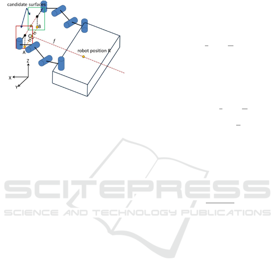
Figure 2: Overview of gripping planes detection.
4 OBSERVATION POSITION
DETECTION
4.1 Method
The robot needs to observe the target object from mul-
tiple positions to obtain appropriate plane information
of the object. To obtain more accurate information,
the number of the observation points should be as
many as possible. However, when many points are
used, it generally takes much time to process. Thus,
we try to make decrease the number of observation
position as possible; we consider three observation
points to obtain valid planes to grip by two manip-
ulation arms.
The robot is in front of the object when start-
ing the autonomous gripping as described in Section
3. Observing the object at the initial position, the
robot needs to decide the following observation points
which should be in the left and right side. In this
study, each position is computed based on the plane
information obtained in the initial observation so that
whole height of the object is captured and the front
plane of the object is captured in the left or right half
of the depth image. The computation model is shown
in Fig. 3: (a) is a side view and (b) is an upper view
to the sensor. We consider the coordinate system de-
picted in the figure. Detecting the positions of the
left and right end points, l(l
x
,l
y
) and r(r
x
,r
y
), on XY
plane and the top and bottom end points, t(t
x
,t
y
) and
b(b
x
,b
y
), on XZ plane by the initial observation in
front of the object, the height and width of the object
become
H
o
= t
z
− b
z
(1)
and
W = l
y
− r
y
(2)
respectively.
Firstly, we determine the distance between the
sensor and the object on XZ plane. The minimum
distance at which the bottom of the object is captured
in the image, D
s
, is computed by
D
s
= H
s
tan
π
2
− θ
s
−
θ
v
2
+ m (3)
where H
s
and θ
s
are the height and the angle of the
mounted sensor, and θ
v
is the vertical visual angle of
the sensor. The margin m is also given so that the
bottom border of the object is captured clearly. In this
case, the captured depth at the height of the object, D
t
becomes
D
t
= (H
s
− H
o
)tan
π
2
− θ
s
+
θ
v
2
(4)
where D
t
= ∞ if (H
s
− H
o
) > 0 and (
θ
v
2
− θ
s
) > 0 be-
cause the top plane of the object is completely cap-
tured in the image.
Next, the observation distance on XY plane is
computed. As shown in Fig. 3 (b), the sensor faces
so that its central axis reaches the left or right end
point. Also, the sensor is located so that the oppo-
site end point is fully captured by the sensor image.
The minimum distance which meets these conditions
is computed by
D
h
= W
sin(θ
h
+ ϕ)
sinθ
h
(5)
where θ
h
is the half value of the horizontal visual an-
gle of the sensor, and ϕ is the angle between the cen-
tral axis of the sensor and the front plane of the object.
As ϕ is larger, a lot of information for lateral planes
can be obtained; on the other side, the error on the
front plane may increase and cause some problem in
integration of plane information at observation points.
We set ϕ = 135 degrees in consideration of the trade-
off between them.
Then, the distance between the sensor and the ob-
ject on XY plane, D, has to be larger than D
b
and
D
h
and less than D
t
. Therefore, we firstly assume
D = max(D
b
,D
h
). This value is determined as D if
D < D
t
. Otherwise, we set D = (D
b
+ D
h
)/2.
Using obtained D, the sensor position on XY
plane at the observation point in the right side,
C
r
(C
rx
,C
ry
), is calculated by
C
r
= r − Dp
r
(6)
where p
r
is a unit vector from C
r
to r and obtained by
p
r
= R(ϕ − π)a
r
(7)
where a
r
is a unit vector from r to l, and R(θ) is a
rotational matrix for θ angle rotation around Z axis.
ICINCO 2019 - 16th International Conference on Informatics in Control, Automation and Robotics
554
!"#$%&
!
"
!
#
$
%
$
#
&
'
&
(
)
*
+
!"#$%&
!
"
'$()*+,
#
$
%
$
&
'
(
"
)
*
"
+
"
!"# !$#
%$&'()
θ
v
θ
s
a
r
p
r
l
r
C
r
θ
h
W
φ
*'+,-.
*'+,-.
D
h
Figure 3: Model for observation position computation
(a):side view to the sensor (b):upper view.
In the same way, the sensor position at the obser-
vation in the left side, C
l
, is calculated by
C
l
= l − Dp
l
(8)
where p
l
is a unit vector from C
l
to l and obtained by
p
l
= −R(π − ϕ)a
r
. (9)
4.2 Computation
We computed the observation points based on the
method mentioned above.
Figure 4 shows the experimental settings for the
computation. Let us consider the described coordi-
nated system in which the center of the robot at the
first observation position O is the origin and forward
direction is corresponding to X axis. The object is a
lightweight box and has 270 mm, 205 mm, and 150
mm in width, length, and height; thus H
o
= 150 mm.
It is located at (572.5, 0, 0) mm and the robot is lo-
cated at the first position right in front of the object.
The depth sensor is mounted at (170, 0, 163) mm, thus
H
s
= 170 mm, with the tilt angle θ
s
= 10 degrees. Its
vertical and horizontal visual angles are θ
v
= 45 de-
grees and θ
h
= 31 degrees respectively.
In this settings, the second and third observation
points, P and Q, which are the right and left sides re-
spectively, were computed. The result is shown in
Fig. 5. The margin m was set to 20 mm. Equation
(3) led D
b
= 275.9 mm. Because (H
s
− H
o
) > 0 and
(
θ
v
2
− θ
s
) > 0, D
t
= ∞ by Equation (4). Equation (5)
also gives D
h
= 126.8 mm. Because of D
h
< D
b
,
D = 275.9 mm, which resulted the sensor position
and robot orientation of (154.7,−450.3) mm and 45
degrees at P, and (154.7,450.3) mm and −45 degrees
at Q. This result shows the valid observation position
because the front plane of the object is fully captured
in the horizontal visual angle of the sensor.
300[mm]
Object
Robot
X
Y
Z
(0,0) [mm]
0 [deg]
205[mm]
270[mm]
(470, -135) [mm]
(470, 135) [mm]
Observation position
Observation position
150[mm]
270[mm]
205[mm]
(572.5, 0) [mm]
Q
O
P
S
(170, 0) [mm]
Figure 4: Experimental setup for observation position cal-
culation.
Figure 5: Computed observation positions and angles of
view.
5 ROBOT SYSTEM
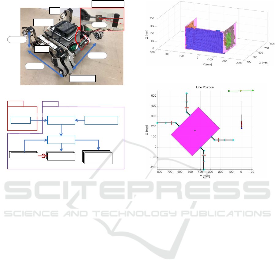
5.1 Quadruped Tracked Robot
We have implemented these presented methods to
quadruped tracked mobile robot which has been de-
veloped by the authors (Fujita and Tsuchiya, 2015).
Figure 6 shows an overview of the robot. This robot
consists of two tracks which drive independently and
four 4DOF legs which can be used as manipulation
arms. The size of the robot body is 390 mm in length,
420 mm in width, and 170 mm in height. Each
of front two legs has a hand unit at the end. The
hand unit consists of two curved grippers and can be
opened in any angle so that it holds an object having
a variety of shape and size; the robot is able to grip an
object that has up to 550 mm in width by using two
legs.
A depth sensor “Camboard pico flex” by pmd Co.
Ltd., the visual angle of which is 60 × 45 degrees and
pixel size is 171 × 224 pixels, is mounted on the cen-
ter of the robot body at the height of 163 mm and the
170 mm front from the robot center by tilting 10 de-
grees. The robot is able to obtain depth information of
the area in front of the robot. The computation for de-
tecting object planes, possible gripping positions, and
observing points are performed by a host PC LIVA
Z (Intel Pentium Processor N4200 1.10 GHz, four
Autonomous Gripping and Carrying of Polyhedral Shaped Object based on Plane Detection by a Quadruped Tracked Mobile Robot
555
Hand Unit
Host PC
Leg
Track
Depth Sensor
390[mm]
170[mm]
420[mm]
10[deg]
Figure 6: Quadruped tracked mobile robot.
Rotary encoder
Operator
Micro computer
mbed LPC1768
DC motors
TG-85R-SU
Servo motors
KRS-6003HV
KRS-4034HV
Track driving
Robot arms driving
rotation angle
Rotary encoder
rotation speed
rotation speed
Robot
Host PC
LIVA Z
Remote PC
Depth Sensor
Camboard pico flexx
robot position
and
arm angle
depth image
Command
Figure 7: Control system.
cores, 16 GB RAM) which is mounted on the top of
the robot body.
5.2 Control System
Figure 7 shows the control system for the robot ex-
plained above. The track driving and joint angles are
controlled by LPC1768, which is an ARM mbed mi-
crocomputer.
The host PC on the robot controls the autonomous
motion for object gripping and carrying as well as
the data processing of the depth sensor and command
sending to the microcomputer. An operator sends a
motion command to the host PC using the remote PC
through wireless network. Because the robot has not
mounted a camera yet, the operator moves the robot
remotely by watching the robot and object so that it
faces right in front the object in this experiment. The
robot then starts the autonomous object gripping and
carrying based on the presented method.
6 EXPERIMENTS
6.1 Gripping Position Detection
The proposed method for detecting gripping planes
and positions was examined. As the first experiment,
Left side plane
Right side plane
Front plane
Figure 8: Detected planes of the object.
B (556.3, -113.5)
(550.9, 120.4) A
(553.6, 3.46)
C
f
Obtained position
R
1
(247.4, -4.23)
(227.4, -4.73) R
2
(154.7, 450.3 )
Q
R
3
(207.4, -5.23)
(187.4, -5.73) R
4
Figure 9: Obtained possible gripping positions.
the robot was placed manually at the observation po-
sitions and orientations obtained in the computation
described in Section 4.2 in the same setting as shown
in Fig. 4. In this experiment, we divided the depth
image by 5 pixels interval to make small region, and
the planes for the regions were integrated by giving
10 degrees allowance as the angle of identical normal
vector. In addition, we assumed the planes that were
integrated by 10 or less small planes as noises and
eliminated them.
Figure 8 shows a result of detected integrated
planes. The blue, green, and yellow planes show
detected front, right, and left planes. The magenta
planes show the actual planes of the object. This re-
sult shows that three planes of the object were de-
tected almost correctly.
Figure 9 shows the result of the detection of pos-
sible gripping positions of the robot. Four possible
positions, R
1
, R
2
, R
3
, and R
4
were obtained from the
detected planes shown in Fig. 8.
Figure 10 shows the result of the gripping posi-
tion selected from the possible positions. The robot
position when they were detected was (154.7, 450.3)
mm. Thus, R
4
was selected because it is the shortest
distance to move, 457.2 mm, from the position of the
robot.
ICINCO 2019 - 16th International Conference on Informatics in Control, Automation and Robotics
556
(187.4,-5.73)[mm]
1.44[deg]
R
4
Figure 10: Obtained robot position and arm postures for
gripping target object.
Figure 10 also shows the postures of both manip-
ulation arms when gripping the target object. These
postures were computed by using inverse-kinematics
in detecting possible gripping positions.
These results show that the robot is able to detect
valid information for grasping the target object prop-
erly.
6.2 Autonomous Gripping and
Carrying
We conducted an experiment to examine an au-
tonomous gripping and carrying with the detection of
observation points. The experiment was employed on
the flat floor in an office room with the same setup
to that shown in Fig. 4. The robot was initially at
the origin and detected plane information as well as
the width and height of the target object at the posi-
tion. Then the left and right observation points were
computed and moved to these positions. The planes
detected at three observation points were integrated
and possible gripping positions and orientations of the
robot with arm postures were computed. The robot fi-
nally moved to the gripping position and performed
gripping and carrying of the object. Two paths of
movement to the observation points were applied: the
order of O, P, and Q, or O, Q, and P. Five experiments
were performed for each path of movement.
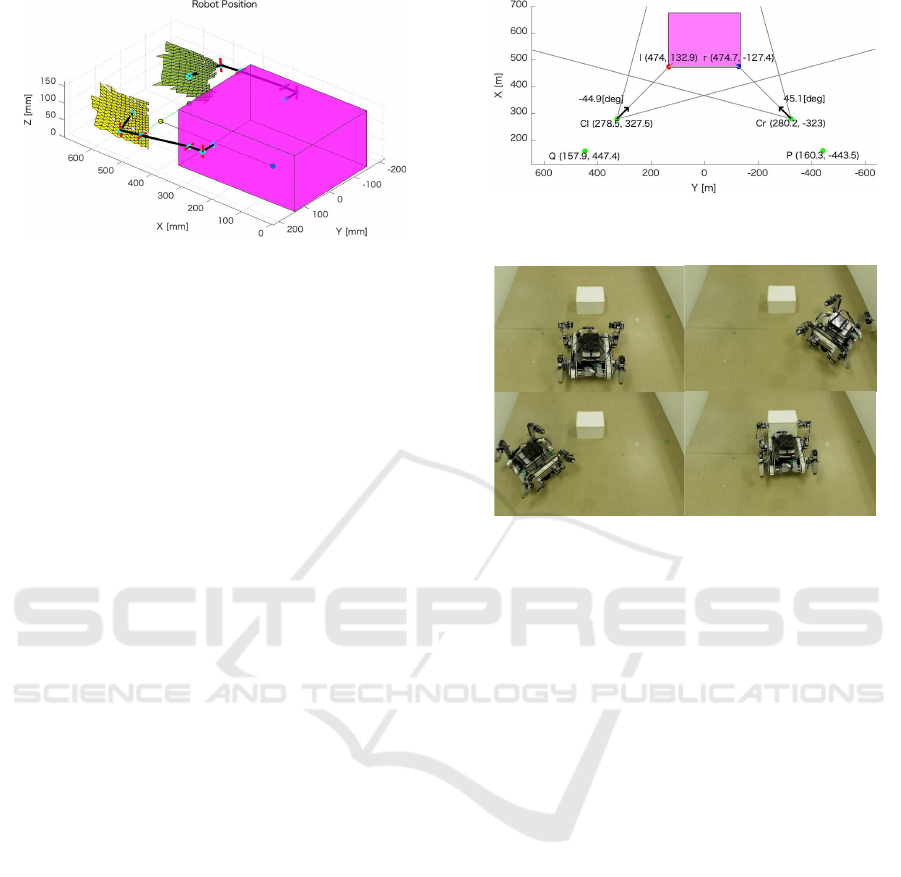
Figure 11 shows a result of computed observation
positions. The detected size of the object was 260.1
mm in width and 148.0 mm in height. The magenta
area shows actual object position. The computed po-
sitions and orientations at the right and left observa-
tion points, P and Q, were (160.3, -443.5) mm and
44.9 degrees at P, and (157.9,447.4) mm and -45.1
degrees, respectively. Although these had errors from
ideal positions and orientations computed in Section
4.2 for the both positions, the front plane of the object
was captured in the view of the sensor to satisfy given
condition in computation of the observation points.
Figure 11: Detected observation positions with angles of
view.
!"#
!$#
!%#
!&#
Figure 12: Sequential motion of autonomous gripping and
carrying action.
An overview of sequential motion of the robot is
shown in Fig. 12. The robot started observation of the
target object in front of it in (a), detected its plane in-
formation, and obtained next two observation points,
P and Q. Then the robot moved to the right observa-
tion point P and detected plane information in (b), and
the left observation point Q in (c) as well. The plane
information detected from three observation points
were then integrated and determined the gripping po-
sition and orientation of the robot. The robot moved
the position and gripped and carried the target object
in (d) by moving both arms based on the joint angles
computed by inverse kinematics in the detection of
possible gripping positions of the robot.
Figure 13 shows position errors of center points on
detected planes in the experiment for the movement
from the right to the left observation points, from P to
Q. The averages and standard deviations of five exper-
iments for this path of movement are indicated. The
left two bars show the result in the first experiment
described in Section 6.1; the robot was placed manu-
ally at the ideal observation positions. The right two
bars show the result in this experiment. As the result,
this experiment had larger errors than the first exper-
iment, especially for the left plane. We can see that
these errors were generated due to localization errors
with odometry by actual movement of the robot. The
errors in the processes for the detection of plane in-
formation must be accumulated as the robot moves.
Autonomous Gripping and Carrying of Polyhedral Shaped Object based on Plane Detection by a Quadruped Tracked Mobile Robot
557

!"!
#!"!
$!"!
%!"!
&!"!
'!"!
(!"!
)!"!
*!"!
+!"!
,-./0123456 7680123456 ,-./0123456 7680123456
9:6431;<=6>?40-;512;=-0-;5 @;A2B06:1;<=6>?40-;512;=-0-;5
C;=-0-;516>>;>DAAE
Figure 13: Errors of center positions of detected planes
when moving from the right to left observation points.
!"!
#!"!
$!"!
%!"!
&!"!
'!"!
(!"!
)!"!
*!"!
+,-./012345
643234578
+,-./012345
64-3234579
:/36635;
64-32345
<3-215=.7.//4/>??@
Figure 14: Errors of observation and gripping positions of
the robot when moving from the right to left observation
points.
In fact, as shown in Fig. 14, the actual position er-
ror for the third observation point Q increased to that
for the second point P. The same tendency was re-
sulted in the experiment for another path of the move-
ment; the errors for the plane obtained at the third ob-
servation point P were larger than that at the second
observation point Q.
The error of detected gripping position is also
shown in Fig. 14. This was also influenced by the
errors of observation positions because it is the last
destination after the movement of two observation
points. However, we can consider that the error is
allowable for the autonomous gripping and carrying
by this robot as shown in Fig. 12.
7 CONCLUSIONS
This paper presented a method for autonomous object
gripping and carrying for a tracked mobile robot with
manipulation arms toward autonomous transportation
task in a dangerous site for human. The proposed
method enables the robot to obtain gripping position
of a polyhedral shaped object based on plane detec-
tion. Experimental results showed validity of this
method in an environment on the flat floor. As future
works, the errors derived from position errors in lo-
calization should be decreased. Furthermore, we also
need to consider correspondence to robust detection
in practical environment with uneven terrain.
REFERENCES
Fujita, T. and Sasaki, T. (2017). Development of Hexa-
pod Tracked Mobile Robot and Its Hybrid Locomo-
tion with Object-Carrying. In 2017 IEEE Interna-
tional Symposium on Robotics and Intelligent Sensors
(IRIS2017), pages 69–73.
Fujita, T. and Tsuchiya, Y. (2014). Development of a
Tracked Mobile Robot Equipped with Two Arms. In
The 40th Annual Conference of the IEEE Industrial
Electronics Society (IECON 2014), pages 2738–2743.
Fujita, T. and Tsuchiya, Y. (2015). Development of a
Quadruped Tracked Mobile Robot. In The ASME
2015 International Design Engineering Technical
Conferences & Computers and Information in Engi-
neering Conference IDETC/CIE.
Gu, S., Su, M., Zhu, H., Guan, Y., Rojas, J., and Zhang,
H. (2017). Efficient pole detection and grasping for
autonomous biped climbing robots. In 2017 IEEE In-
ternational Conference on Robotics and Biomimetics
(ROBIO), pages 246–251.
Gu, S., Zhu, H., Li, H., Guan, Y., and Zhang, H. (2018).
Optimal collision-free grip planning for biped climb-
ing robots in complex truss environment. Applied Sci-
ences, 8(12).
Harada, K., Tsuji, T., Nagata, K., Yamanobe, N.,
Maruyama, K., Nakamura, A., and Kawai, Y. (2011).
Grasp planning for parallel grippers with flexibility
on its grasping surface. In Proceedings of IEEE In-
ternational Conference on Robotics and Biomimetics,
pages 1540–1546.
Masuda, H. and Lim, H.-o. (2014). Retinal model based
plane detection method using range images for un-
known object recognition (in japanese). Journal of
the Robotics Society of Japan, 32(1):64–73.
Yamazaki, K., Tomono, M., and Tsubouchi, T. (2007).
Picking up and unknown object through autonmous
modeling and grasping by a mobile manipulator. In
Proceedings of the 6th International Conference on
Field and Service Robotics, pages 563–571.
ICINCO 2019 - 16th International Conference on Informatics in Control, Automation and Robotics
558
