Neural Network Contour Error Prediction of a Bi-axial Linear Motor
Positioning System
Krystian Erwinski
a
, Karol Kowalski and Marcin Paprocki
b
Departament of Automatics and Measurement Systems, Faculty of Physics Astronomy and Informatics,
Nicolaus Copernicus University in Torun, Grudziadzka 5, Torun, Poland
Keywords: Following Error, Contour Error, Prediction, Narx Neural Network, NURBS, Linear Motor, Feed Drive Model.
Abstract:
In the article a method of predicting contour error using artificial neural network for a bi-axial positioning
system is presented. The machine consists of two linear stages with permanent magnet linear motors controlled
by servo drives. The drives are controlled from a PC with real-time operating system via EtherCAT fieldbus. A
randomly generated Non-Uniform Rational B-Spline (NURBS) trajectory is used to train offline a NARX-type
artificial neural network for each axis. These networks allow prediction of following errors and contour errors
of the motion trajectory. Experimental results are presented that validate the viability of the neural network
based contour error prediction. The presented contour error predictor will be used in predictive control and
velocity optimization algorithms of linear motor based CNC machines.
1 INTRODUCTION
Multi axis machines are widely used in industrial
manufacturing in the form of numerically controlled
machine tools (CNC) and robots. Each mechanical
axis is driven by a linear or rotary feed drive. Com-
position of their movements constitutes the output
motion trajectory of the machine’s end effector (i.e.
milling tool, laser head, welding head, gripper) also
called a toolpath. Position commands for each feed
drive are generated by interpolating the given tool
path according to pre-planned or on-line generated
velocity profiles.
In order to enhance machine performance much
attention has been given to improving the motion
planning process by developing new feedrate profile
generation algorithms. Several authors propose us-
ing optimization algorithms to generate an optimal
feedrate profile (Xu et al., 2018; Ni et al., 2018;
Zhang et al., 2019). An optimal feedrate profile maxi-
mizes speed while simultaneously respecting the feed
drives’ and machine’s constraints in order to shorten
machining time. Most approaches neglect the influ-
ence of machining errors in the feedrate planning pro-
cess. Machining errors are often defined as contour
errors which are the minimum distances between the
a
https://orcid.org/0000-0001-6899-1785
b
https://orcid.org/0000-0003-2687-1181
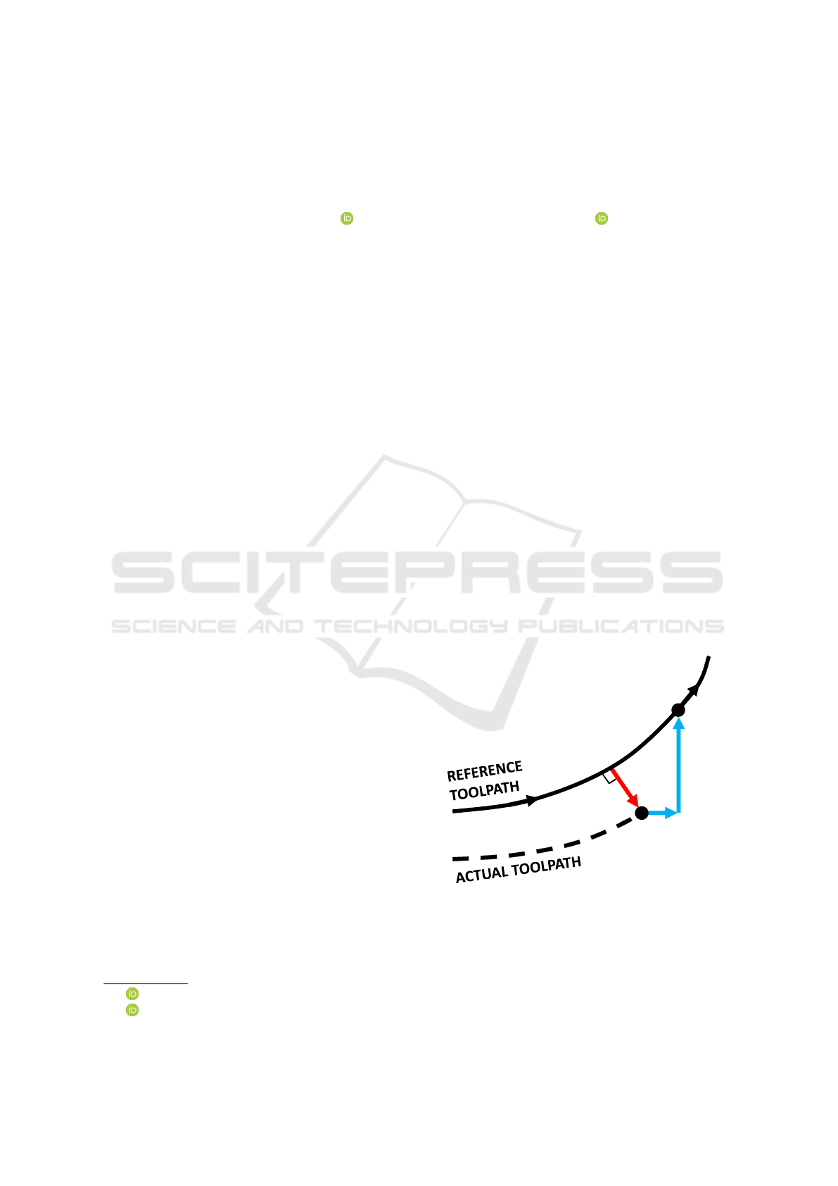
reference toolpath and actual tool positions (Ramesh
et al., 2005; Tang and Landers, 2013) as shown in
figure 1. Some authors propose including error con-
straints in the feedrate planning process but usually
use simplified models that do not accurately predict
actual following errors (Jia et al., 2017).
ɸ
dž
ɸ
LJ
ɸ
Đ
Z
ŝ
W
ŝ
Figure 1: Contour error definition. ε
c
- contour error, ε
x,y
- axis following errors, R
i
- toolpath reference point, P
i
-
actual toolpath point.
Optimizing feedrate with respect to contour er-
ror constraints is especially important for machines
that utilize linear motor feed drives such as laser cut-
ters. These machines can achieve very high speeds
802
Erwinski, K., Kowalski, K. and Paprocki, M.
Neural Network Contour Error Prediction of a Bi-axial Linear Motor Positioning System.
DOI: 10.5220/0007957908020809
In Proceedings of the 16th International Conference on Informatics in Control, Automation and Robotics (ICINCO 2019), pages 802-809
ISBN: 978-989-758-380-3
Copyright
c
2019 by SCITEPRESS – Science and Technology Publications, Lda. All rights reserved
and accelerations which significantly reduces machin-
ing time. At the same time they simultaneously
need to ensure accurate toolpath following. Most
multi axis machines use permanent magnet rotary
synchronous motors which produce rotary motion and
torque. Some mechanism is usually required to con-
vert rotation into linear motion. These are usually
ballscrews, racks and pinions or toothed belts some-
times with an additional reduction gear. Permanent
magnet linear synchronous motors produce linear mo-
tion directly without the need for additional mecha-
nisms. This has the advantage of greatly simplifying
the machines construction and eliminating backlash
and compliance in the feed drive which leads to de-
creased following errors. On the other hand the linear
motor does not have the mechanical advantage pro-
vided by these mechanisms and has to drive the ma-
chines mass directly. Linear motors are controlled us-
ing the same field oriented control techniques used in
rotary motors therefore the same servo drives can usu-
ally be used.
The authors previously developed a feedrate opti-
mization method which accounts for contour error for
traditional ballscrew driven machines (Erwinski et al.,
2016; Szczepanski et al., 2017). A fundamental re-
quirement for such an algorithm is an accurate pre-
dictor which can predict the contour error generated
by the feed drive (both the servo drive and the me-
chanical part). It is important that the parameters of
the predictor used are easy to identify and can be eas-
ily ported to any machine with any servo drive. The
main contribution of the paper is the development of
a contour error predictor that can perform a multi-
step-ahead prediction of the contour error based on
a velocity demand input signal. The proposed pre-
dictor is a non-linear black-box input-output model
that accounts for the dynamics of both the servo drive
and mechanical components of the linear motor feed
drive. This predictor will be used in a multi-axis ma-
chine feedrate optimization algorithm to constrain the
maximum contour error by adjusting the feedrate pro-
file. The authors will implement this approach for lin-
ear motor based machines which will be an extension
of their previous works.
2 BI-AXIAL LINEAR MOTOR
POSITIONING SYSTEM
The linear motor positioning system used in this re-
search consists of two linear motor positioning units
representing X and Y axes of a multi-axis machine.
The positioning units use Tecnotion TM6 iron core
flat linear motors mounted on an aluminium chas-
sis with linear roller guideways. The motors are
controlled by Kollmorgen AKD-P00307 servo drives
with feedback provided by Renishaw optical linear
scales. The high resolution feedback provides po-
sitioning accuracy of around 0.01 micrometre. The
positioning units’ servo drives receive position, ve-
locity or torque commands from a PC-based numeri-
cal controller via EtherCAT fieldbus (Jansen and But-
tner, 2004; Paprocki et al., 2018). The PC controller
runs TwinCAT 3 real-time control software on a stan-
dard Windows 10 operating system. Special real-time
mechanism implemented in TwinCAT such as pro-
cessor core isolation ensure hard real-time operation
of the CNC controller. This allows for implementa-
tion of typical PLC or CNC controllers in software
without any dedicated hardware extensions. Twin-
CAT also implements a real-time EtherCAT commu-
nication stack and driver which enables determinis-
tic communication with many commercial automa-
tion equipment such as servo drives or input output
devices.
TwinCAT also enables the user to implement cus-
tom real-time control programs in C++. This ap-
proach was used in this research to develop a trajec-
tory interpolator for both linear axes. The intepolator
generates position commands in 250 microsecond in-
tervals and sends them over EtherCAT to the drives
to realize the reference motion trajectory. The de-
veloped software can also send direct commands to
the drive over Ethercat to initiate the device, perform
homing, clear errors and change between position, ve-
locity and torque modes according to the Can in Au-
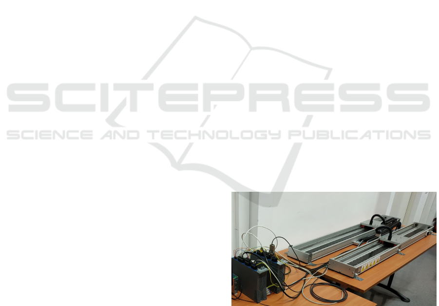
tomation CIA402 device profile. The picture of the
linear motor positioning system test stand is shown of
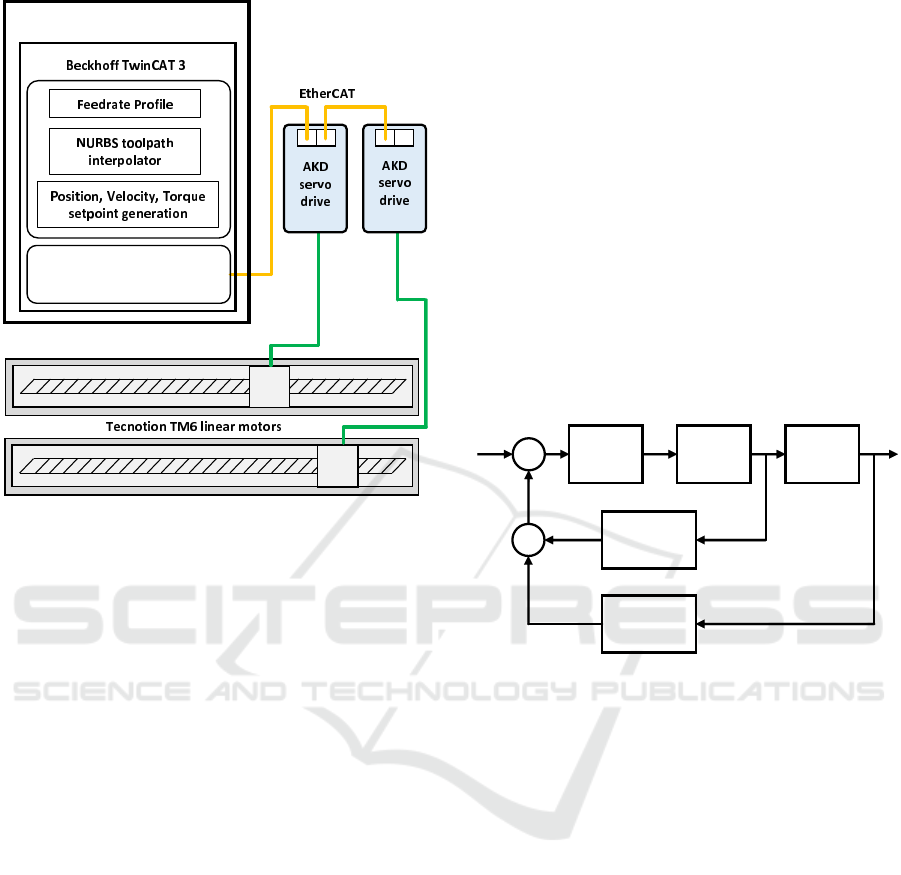
figure 2 and its schematic is shown of figure 3.
Figure 2: Linear motor positioning system test stand.
The linear motor motion path is defined as a third
order Non-Uniform Rational B-Spline (NURBS)
(Piegl and Tiller, 2012). Such path description is often
used in CNC machining because of guaranteed conti-
nuity, ability of local shape modification and ability
to easily describe complex shapes (Heng and Erkork-
maz, 2010; Liu et al., 2015). Interpolation of NURBS
Neural Network Contour Error Prediction of a Bi-axial Linear Motor Positioning System
803
ƚŚĞƌd /ϰϬϮ
ƌĞĂůͲƚŝŵĞ ĚƌŝǀĞƌ
WͲďĂƐĞĚ ĐŽŶƚƌŽůůĞƌ
Figure 3: Linear motor positioning system test stand
schematic.
toolpaths is performed according to a predefined, op-
timized polynomial feedrate profile. This allows to
maximize drive capabilities without violating their
speed and acceleration limits.
3 LINEAR MOTOR FEED DRIVE
MODEL
Main factors that contribute to the dynamics of the
linear motor positioning system are the mass of the
motor and carriage attached it and guideway friction.
Due to lack of a drive train effects such as backlash
or compliance do not influence the positioning accu-
racy. An additional effect typical of flat iron core lin-
ear motors is the cogging force. This force is due to
the attraction between the motor’s iron core and the
permanent magnets and is dependent on their relative
position. This causes a periodic force ripple the fre-
quency of which is proportional to the motor speed
and magnet pitch (distance between adjacent magnet
poles).
The cogging force has significant effect on po-
sitioning accuracy mainly at low speeds. Because
this effect depends only on motor position it can be
mapped and eliminated by using static feedforward
compensation. This functionality is implemented in
the Kollmorgen AKD servodrives and was used in this
research to significantly eliminate its effect on posi-
tioning accuracy.
Friction force is influenced by several friction
components. When the drive tries to move the mo-
tor from standstill it has to overcome static friction.
Then as the speed increases the friction force drops
and after reaching a certain speed rises again. This
is called the Stribeck effect and the velocity at which
the friction minimum is reached is the Stribeck ve-
locity. Friction then increases as a linear function of
speed and this component is called the viscous fric-
tion. There is also a constant velocity independent
component called the Coulomb friction which de-
pends only on mass. Friction is usually assumed to be
symmetric for positive and negative velocities. This
is not always the case if the motion unit is inclined or
the guideways are not exactly parallel to each other.
A block schematic of the linear motor feed drive is
presented in figure 4.
1/M
v
a
x
F
F
cog
F
fri
ŶŽŶͲůŝŶĞĂƌ
ĨƌŝĐƚŝŽŶ
ĐŽŐŐŝŶŐ
ĨŽƌĐĞ
+
+
-
+
Figure 4: Linear motor model, M - motor and carriage mass,
a - motor acceleration, v - motor speed, x - motor position,
F
f ri
- friction force, F
cog
- cogging force.
In order to identify the Linear Motor Feed Drive
Model a series of experiments were performed on the
system. In order to identify carriage mass a current
step command of 2A was issued and actual veloc-
ity was measured. Total carriage and motor forcer
mass was identified using MATLAB System Identifi-
cation Toolbox to be 3.61kg. In order to identify fric-
tion a series of constant positive and negative veloc-
ity movements were performed in velocity mode from
0.1 mm/s to 2000 mm/s. Motor current was measured
for each run in order to determine the friction force.
This current was averaged to eliminate any force rip-
ples and multiplied by the motor force factor Kf equal
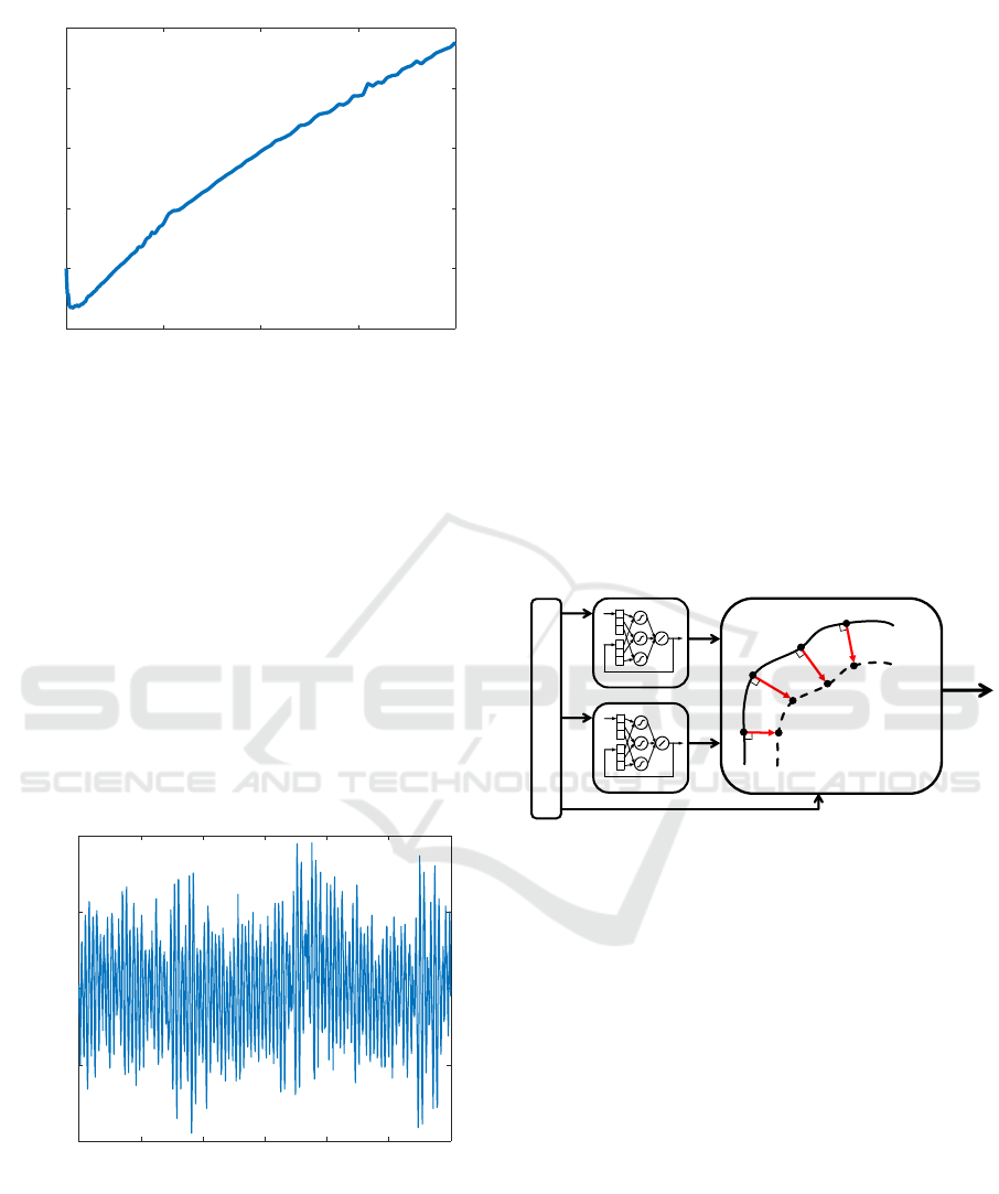
to 39. The resulting friction map is shown in figure 5.
It can be clearly seen that for large velocities from
about 500mm/s the viscous does not increase linearly
with the increase in speed as is usually assumed. The
discrepancy between a linear friction characteristics
and actual friction curve is significant at large speeds.
For 2 m/s the actual friction current is 20% smaller
than a linear friction model would predict. The linear
motor also has a large static friction requiring about
ICINCO 2019 - 16th International Conference on Informatics in Control, Automation and Robotics
804
0 500 1000 1500 2000
Velocity [mm/s]
400
500
600
700
800
900
Friction Current [mA]
Figure 5: Current due to friction as a function of velocity.
500mA current to start motion. This was identified by
generating a ramp current command and recording the
amount of current at which the motor starts to move.
This is caused by large magnet attraction forces and
lack of mechanical advantage offered by traditional
drive train mechanisms.
Cogging force was also identified during constant
velocity movement of 5 mm/s. Because this effect
is depends motstly on motor position a current ver-
sus position table can be recorded and used for feed-
forward compensation. Figure 6 presents the drive
current as a function of position. The period corren-
sponds to distance of 12mm which is the distance be-
tween north and south poles of the permanent magnet
track.
0 200 400 600 800 1000 1200
Position [mm]
-0.5
-0.25
0
0.25
0.5
Current [A]
Figure 6: Linear motor (Tecnotion TM6) current due to cog-
ging force at constant speed of 5 mm/s in velocity mode.
It is clear that the linear motor positioning system
although mechanically very simple has non-linear
characteristics. Identification of a model presented in
fig. 4 is time consuming and requires switching the
drive to velocity and torque modes. This is not always
possible on commercial multi-axis machines. Also
when using off-the-shelf servo drives the actual con-
troller structure is not always precisely known. Due
to these problems a black box modelling approach is
used instead in order to obtain following and contour
error predictions.
4 NARX NEURAL NETWORK
CONTOUR ERROR
PREDICTION
In order to obtain contour error predictions of a linear
motor positioning system with NURBS motion path
definition following error prediction of each axis have
to be determined first. Predicted following errors are
combined with information about local toolpath ge-
ometry to obtain and estimated contour error. The
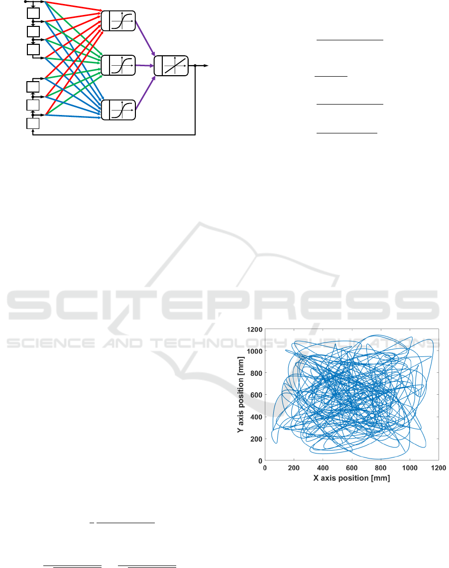
structure of a neural network contour error predictor
is shown in figure 7.
EhZ^/EdZWK>dKZ
s
dž
ɸ
dž
ɸ
LJ
EhZ>EdtKZ<
&K>>Kt/E'ZZKZWZ/dKZ^
KEdKhZZZKZ
KDWhdd/KE
ɸ
Đ
EhZ^dKK>Wd,'KDdZz
s
LJ
Z
ŝ
Z
ŝнϭ
Z
ŝнϮ
Z
ŝнϯ
W
ŝнϭ
W
ŝнϮ
W
ŝнϯ
W
ŝ
Figure 7: Structure of neural network prediction block.
Prediction of axis following errors is performed
by using a Non-Linear Auto Regressive Exogenous
Input Neural Network (NARX). Such networks dif-
fer from traditional multi-layered perceptrons (MLP)
by adding a feedback between output and input lay-
ers and delays in the input layer. This allows to
model non-linear dynamical systems. An example of
a NARX neural network used for following error pre-
diction is presented in figure 8. Reference velocity
obtained from differentiating polynomial toolpath and
feedrate profile is used as input.
Training the network is a process of minimizing
the mean squared errors based on error backpropa-
gation. Training of the NARX following error pre-
dictor is performed first in series-parallel form where
the network feedback is disconnected and target series
(following error) is fed into the network along the in-
put signal (reference velocity). In this form standard
static network training algorithms are used (Xie et al.,
2009). Training is finished when the prediction error
Neural Network Contour Error Prediction of a Bi-axial Linear Motor Positioning System
805
nj
Ͳϭ
nj
Ͳϭ
nj
Ͳϭ
ǀ;ƚͲϮͿ
ǀ;ƚͿ
ǀ;ƚͲϯͿ
Ğ;ƚͲϯͿ
Ğ;ƚͲϮͿ
Ğ;ƚͲϭͿ
ǀ;ƚͲϭͿ
nj
Ͳϭ
nj
Ͳϭ
nj
Ͳϭ
Ğ;ƚͿ
н
н
н
н
Figure 8: Example structure of a NARX neural network
used for following error prediction.
stops decreasing. The feedback is then reconnected
and training is continued in parallel form. In this
form dynamic training algorithms such as backpropa-
gation through time have to be used. These are more
computationally demanding and are sensitive to ini-
tial weight values (Horne and Giles, 1995). Weights
obtained from the series-parallel training phase are
used as initial guess for parallel training which gives
good initial values and decreases total training time.
Training is finished when the prediction error does not
change significantly for some period of time. MAT-
LAB Neural Network Toolbox function TRAINBR is
used to train the network.
If motion paths are defined as Non-Uniform
Rational B-Splines (NURBS) or other polynomial
curves the contour error cannot be computed exactly
and has to be estimated (Uchiyama et al., 2011). Sev-
eral contour error estimation techniques for free-form
toolpaths have been proposed (Yeh and Hsu, 2002;
Huo et al., 2012; Sencer et al., 2009; Chen et al.,
2008). All of these are either simple estimates which
have large errors for curves with high curvatures or
are computationally demanding. In one interesting
algorithm proposed in (Zhu et al., 2013) the contour
error vector is approximated by a Taylor series which
yields accurate estimates without high computational
demand. This method was chosen for developing the
contour error predictor. The contour error is estimated
using the following closed form formula:
~
ε
c
=
−~c −
1
2
κ ( ˆc · ˆn)(
ˆ
t ·
~
ε
t
)
ˆ
t
1 −κ (ˆc · ˆn)
·
~
ε
t
(1)
ˆc = −
~
ε
t
·
ˆ
t
p
||
~
ε
t
||
2
−
~
ε
t
·
ˆ
t
ˆ
t +
1
p
||
~
ε
t
||
2
−
~
ε
t
·
ˆ
t
~
ε
t
(2)
where: κ - toolpath curvature at the reference
point,
ˆ
t, ˆn - tangent and normal unit vectors at the ref-
erence point,
~
ε
t
- following error vector. Curvature,
tangent and normal vectors can be computed using the
following formulas:
κ =
||C
0
(u) ×C
00
(u)||
||C
0
(u)||
3
(3)
ˆ
t =
C
0
(u)
||C
0
(u)||
ˆ
b =
C
0
(u) ×C
00
(u)
||C
0
(u) ×C
00
(u)||
ˆn =
ˆ
b(u) ×C
0
(u)
||
ˆ
b(u) ×C
0
(u)||
(4)
where: C
0
(u),C
00
(u) - are first and second derivatives
of the NURBS toolpath position vector with respect
to the toolpath parameter u obtained from the NURBS
interpolator.
5 EXPERIMENTAL RESULTS
In order to generate training data for training the con-
tour error predictor a NURBS trajectory was con-
structed by randomly generating curve control points
in the whole positioning system travel range between
0 and 1200mm in both axes. The toolpath used is pre-
sented in figure 9.
Figure 9: Randomly generated NURBS curve motion path
used for neural network training.
A feedrate profile was generated which forced
high variations and values of velocity,acceleration
and jerk in each axis while simultaneously keeping
them within safe limits. The maximum values of ve-
locity, acceleration and jerk were set to 2500mm/s,
25000mm/s
2
and 500000mm/s
3
respectively. This
was done to sufficiently capture following error dy-
namics and avoid drive saturation and positioning sys-
tem damage. The motion path was executed using the
ICINCO 2019 - 16th International Conference on Informatics in Control, Automation and Robotics
806
feedrate profile using the PC-based controller control-
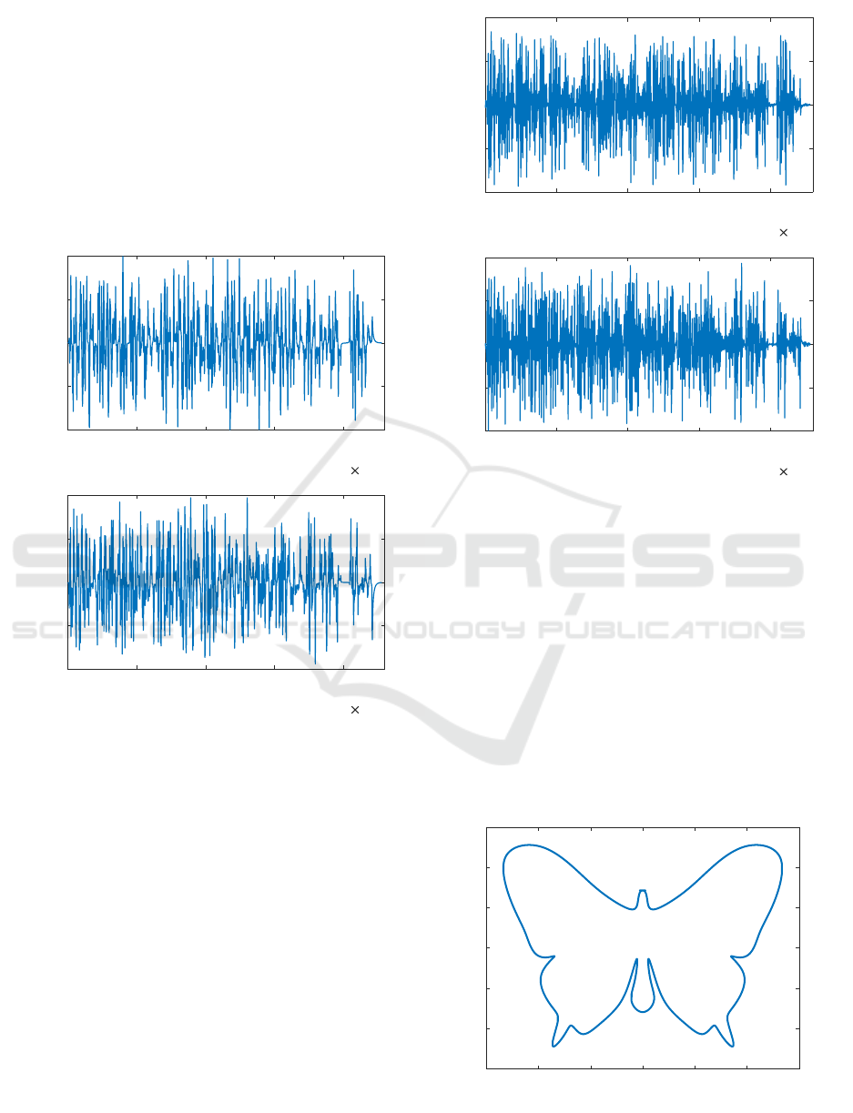
ling the linear motor positioning system. Axis veloc-
ity demand and actual following error for each axis
were recorded and transfered to MATLAB. Datasets
of velocity demand (input) and following error (tar-
get) were generated with 455559 samples (at 0.25 ms
sampling rate) for both X and Y axes. The velocity
demand signal and following errors are shown on fig-
ures 10 and 11. Only the first half of each dataset was
used as a training set. The second half was used for
validation.
0 1 2 3 4
10
5
-3000
-1500
0
1500
3000
X axis velocity [mm/s]
0 1 2 3 4
sample number
10
5
-3000
-1500
0
1500
3000
Y axis velocity [mm/s]
Figure 10: Velocity demand for x and y axes (input values)
used in training and testing.
Training was performed for each axis NARX neu-
ral network multiple times in order to determine the
best network architecture (trial and error approach)
by using an automated script in MATLAB. Each net-
work was trained first in series-parallel mode and then
further trained in parallel mode. A training period of
2000 epochs and 4000 epochs in the series-parallel
and parallel mode respectively was used. A NARX
neural network with 5 input, 4 feedback delays and 6
sigmoid hidden neurons was chosen as the following
error predictor for X and Y axes. This network struc-
ture achieved the lowest following error prediction
mean squared error. Prediction mean squared error of
6.59e-4 mm and 4.75e-4 mm was achieved for the X
and Y axis respectively. If only series-parallel train-
ing was to be used, the training would complete much
faster but at the cost of much worse mean squared pre-
0 1 2 3 4
10
5
-0.8
-0.4
0
0.4
0.8
X axis following error [mm]
0 1 2 3 4
Sample number
10
5
-0.8
-0.4
0
0.4
0.8
Y axis following error [mm]
Figure 11: Following error for x and y axes (target values)
used in training and testing.
diction error (5e-1 mm average).
In order to test the contour error prediction error
for a typical trajectory another toolpath was used. The
obtained neural network contour error predictor was
used to verify contour error prediction accuracy of a
butterfly curve (figure 12). An appropriate feedrate
profie with the same limits as stated above was gen-
erated. The curve was run on the linear motor po-
sitioning system and actual contour error was com-
puted and compared with values predicted from the
proposed predictor.
0 200 400 600 800 1000 1200
X axis position [mm]
0
200
400
600
800
1000
1200
Y axis position [mm]
Figure 12: Butterfly NURBS curve motion path.
Neural Network Contour Error Prediction of a Bi-axial Linear Motor Positioning System
807
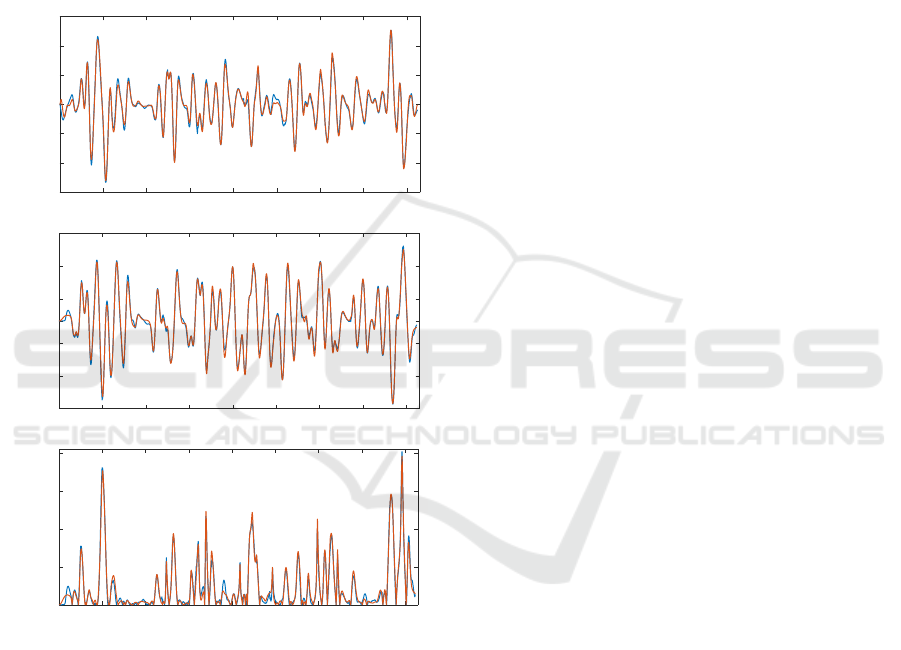
Figure 13 presents a comparison of following and
contour error resulting from realizing the actual mo-
tion path and predicted using the NARX contour error
predictor. The mean squared error (MSE) of contour
error prediction is 2.6921e-04 mm. It can be seen that
the predictor is able to accurately predict actual fol-
lowing errors and by extent the actual contour error.
It should be noted that the test toolpath was not used
in the neural network training process and the accu-
rate prediction is due to neural network generalization
abilities.
0 1 2 3 4 5 6 7 8
-0.6
-0.4
0.2
0
0.2
0.4
0.6
X following error [mm]
0 1 2 3 4 5 6 7 8
-0.6
-0.4
0.2
0
0.2
0.4
0.6
Y following error [mm]
0 1 2 3 4 5 6 7 8
time [s]
-0.6
-0.4
0.2
0
0.2
contour error [mm]
Figure 13: Predicted (orange) and actual (blue) follow-
ing error and contour error for validation dataset (butterfly
curve).
6 CONCLUSION
The article presents a contour error predictor for a bi-
axial linear motor positioning system based on neural
networks. Experimental results are presented which
show that linear motor exhibits non-linear dynamics
mainly due to non-linear friction at very low and very
high speeds. Due to complexity of identifying partic-
ular friction components and potentially incomplete
information about the commercial drive control struc-
ture a black box approach to predicting contour error
is proposed. This approach uses NARX neural net-
works to predict following errors of each axis. This in
turn is used to estimate contour error based on local
motion path geometry.
Experimental results show good accuracy in pre-
dicting contour error of a NURBS motion path. Ma-
jor advantage of this approach is the quick and easy
identification procedure. Actual toolpaths can be used
with following errors obtained during normal ma-
chine operation. Identification experiments in veloc-
ity and torque modes are not required. The neural
network can generalize and accurately predict actual
following and contour errors for toolpaths not used in
the training process.
The main contribution of this paper is developing
a fast and easy to use method to predict contouring
error in multi axis positioning systems such as CNC
machine tools. Compared to other modelling tech-
niques in literature this approach can use following
error data collected during normal machine opera-
tion. This allows considerable time savings because
dedicated identification experiments in velocity and
torque modes are avoided. The contour error predic-
tor will be used to develop an on-line feedrate op-
timization method for linear motor based multi axis
machines. Using The contour error predictor can also
be used for predictive control of such machines. Pre-
dictive techniques require a model to generate an op-
timal control signal. The proposed predictor in the
form of NARX neural networks is easy to implement
and computationally efficient.
ACKNOWLEDGEMENTS
This research has been financed from the funds of the
Polish Ministry of Science and Higher Education for
statutory R&D activities supporting the development
of young scientists and PhD students (internal grant
no. 1035-F/2018)
REFERENCES
Chen, X., Yong, J., Wang, G., Paul, J., and Xu, G.
(2008). Computing the minimum distance between
a point and a nurbs curve. Computer-Aided Design,
40(10):1051–1054.
Erwinski, K., Paprocki, M., Wawrzak, A., and Grzesiak,
L. M. (2016). Pso based feedrate optimization with
contour error constraints for nurbs toolpaths. In 2016
21st International Conference on Methods and Mod-
ICINCO 2019 - 16th International Conference on Informatics in Control, Automation and Robotics
808

els in Automation and Robotics (MMAR), pages 1200–
1205. IEEE.
Heng, M. and Erkorkmaz, K. (2010). Design of a nurbs in-
terpolator with minimal feed fluctuation and continu-
ous feed modulation capability. International Journal
of Machine Tools and Manufacture, 50(3):281–293.
Horne, B. G. and Giles, C. L. (1995). An experimental
comparison of recurrent neural networks. In Advances
in neural information processing systems, pages 697–
704.
Huo, F., Xi, X.-C., and Poo, A.-N. (2012). Generalized
taylor series expansion for free-form two-dimensional
contour error compensation. International Journal of
Machine Tools and Manufacture, 53(1):91–99.
Jansen, D. and Buttner, H. (2004). Real-time ethernet: the
ethercat solution. Computing and Control Engineer-
ing, 15(1):16–21.
Jia, Z.-y., Song, D.-n., Ma, J.-w., Hu, G.-q., and Su, W.-
w. (2017). A nurbs interpolator with constant speed
at feedrate-sensitive regions under drive and contour-
error constraints. International Journal of Machine
Tools and Manufacture, 116:1–17.
Liu, H., Liu, Q., Zhou, S., Li, C., and Yuan, S. (2015).
A nurbs interpolation method with minimal feedrate
fluctuation for cnc machine tools. The Interna-
tional Journal of Advanced Manufacturing Technol-
ogy, 78(5-8):1241–1250.
Ni, H., Hu, T., Zhang, C., Ji, S., and Chen, Q. (2018).
An optimized feedrate scheduling method for cnc ma-
chining with round-off error compensation. The In-
ternational Journal of Advanced Manufacturing Tech-
nology, 97(5-8):2369–2381.
Paprocki, M., Wawrzak, A., Erwinski, K., and Klosowiak,
M. (2018). Flexible pc-based cnc machine control sys-
tem. Mechanik, 91(4):299–303.
Piegl, L. and Tiller, W. (2012). The NURBS book. Springer
Science & Business Media.
Ramesh, R., Mannan, M., and Poo, A. (2005). Tracking
and contour error control in cnc servo systems. Inter-
national Journal of Machine Tools and Manufacture,
45(3):301–326.
Sencer, B., Altintas, Y., and Croft, E. (2009). Modeling
and control of contouring errors for five-axis machine
tools. part i: Modeling. Journal of manufacturing sci-
ence and engineering, 131(3).
Szczepanski, R., Erwinski, K., and Paprocki, M. (2017).
Accelerating pso based feedrate optimization for
nurbs toolpaths using parallel computation with
openmp. In 2017 22nd International Conference
on Methods and Models in Automation and Robotics
(MMAR), pages 431–436. IEEE.
Tang, L. and Landers, R. G. (2013). Multiaxis contour con-
trol—the state of the art. IEEE Transactions on Con-
trol Systems Technology, 21(6):1997–2010.
Uchiyama, N. et al. (2011). Contouring controller design
based on iterative contour error estimation for three-
dimensional machining. Robotics and Computer-
Integrated Manufacturing, 27(4):802–807.
Xie, H., Tang, H., and Liao, Y.-H. (2009). Time series
prediction based on narx neural networks: An ad-
vanced approach. In 2009 International conference
on machine learning and cybernetics, volume 3, pages
1275–1279. IEEE.
Xu, G., Chen, J., Zhou, H., Yang, J., Hu, P., and Dai, W.
(2018). Multi-objective feedrate optimization method
of end milling using the internal data of the cnc sys-
tem. The International Journal of Advanced Manu-
facturing Technology, pages 1–17.
Yeh, S. and Hsu, P. (2002). Estimation of the contour-
ing error vector for the cross-coupled control design.
IEEE/ASME Transactions on Mechatronics, 7(1):44–
51.
Zhang, Y., Ye, P., Zhao, M., and Zhang, H. (2019). Dy-
namic feedrate optimization for parametric toolpath
with data-based tracking error prediction. Mechani-
cal Systems and Signal Processing, 120:221–233.
Zhu, L., Zhao, H., and Ding, H. (2013). Real-time con-
touring error estimation for multi-axis motion systems
using the second-order approximation. International
Journal of Machine Tools and Manufacture, 68(5):75–
80.
Neural Network Contour Error Prediction of a Bi-axial Linear Motor Positioning System
809
