A Novel Aerial Manipulation Design, Modelling and Control for
Geometric CoM Compensation
Kamel Bouzgou
1,2 a
, Laredj Benchikh
1 b
, Lydie Nouveliere
1 c
, Yasmina Bestaoui
1 d
and Zoubir Ahmed-Foitih
2 e
1
IBISC, Univ. Evry, Universit
´
e Paris-Saclay, 91025, Evry, France
2
LEPESA Laboratory, Faculty of Electrical Engineering, Department of Electronics, USTO-MB, 31000 Oran, Algerie
Keywords:
UAVs, Aerial Robot, Flying Manipulation, CLIKA, CoM Compensation, Dynamic Inverse Control.
Abstract:
This paper presents the design and modelling of a new Aerial manipulating system, that resolve a displacement
of centre of gravity of the whole system with a mechanical device. A prismatic joint between the multirotor
and a robotic arm is introduced to make a centre of mass as close as to the geometric centre of the whole
system. This paper details also the geometric and dynamic modelling of a coupled system with a Lagrange
formalism and control law with a Closed Loop Inverse Kinematic Algorithm (CLIKA). This dynamic inverse
control is validated in a Simulink environment showing the efficiency of our approach.
1 INTRODUCTION
Unmanned Aerial Vehicles (UAVs) becomes an im-
portant scientific field, Interesting applications would
be filming scenes and snapshots, exploring a wide
area, observing aspects for civil and military tasks,
then recently in the road traffic. The beginning of the
robotics was to help the industrialists to make com-
plex tasks in a fast and precise way, the environment
was the ground, when the flying machines appeared,
the researchers discovered another field of exploita-
tion, the interaction with the environment was diffi-
cult, It began with the use of cameras and remote sen-
sors without having direct contact with the environ-
ment or the target. Researchers are on the use of dif-
ferent mechanisms to interact on targets, this is where
they created the domain of flying manipulators.
In the last few years, it has emerged a need for the
interaction of that UAVs with the environment that
is not easily accessible by humans, for this, the re-
searchers have used for transporting, manipulation
and grasping a payload, several tools are used: mag-
net, cables, grippers and manipulators, also a combi-
nation of all that, to ensure the target tasks.
a
https://orcid.org/0000-0003-2374-2149
b
https://orcid.org/0000-0002-4617-399X
c
https://orcid.org/0000-0003-0027-7192
d
https://orcid.org/0000-0001-7716-5952
e
https://orcid.org/0000-0003-3121-9964
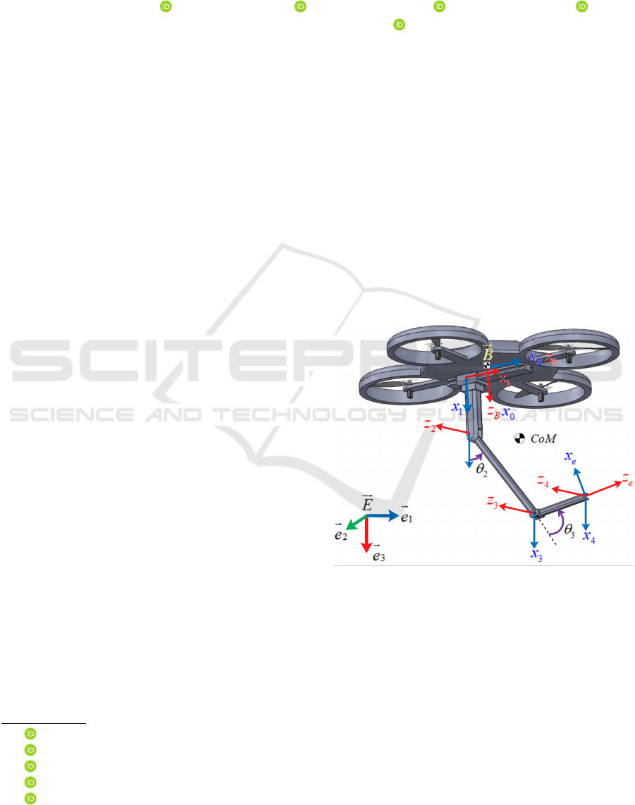
Figure 1: The structure of Q-PRR with principal frames.
Almost systems in the literature consider a
Quadrotor with manipulator arm and for a n DOF,
a robot arm with revolute joints, And they place the
system support which they can’t generate large an-
gles for the first joint, and the result will be a reduced
workspace with an joint limit. Therefore it will be
found that from second joint to n,are the real joints to
generate a real workspace of the robot arm where the
UAV be in the stable position.
A several project in the word that deals the aerial
manipulators are founded, from conception to con-
trol, as an example, the ARCAS project, (Aerial
Robotics Cooperative Assembly System)for assem-
Bouzgou, K., Benchikh, L., Nouveliere, L., Bestaoui, Y. and Ahmed-Foitih, Z.
A Novel Aerial Manipulation Design, Modelling and Control for Geometric CoM Compensation.
DOI: 10.5220/0007951404750482
In Proceedings of the 16th International Conference on Informatics in Control, Automation and Robotics (ICINCO 2019), pages 475-482
ISBN: 978-989-758-380-3
Copyright
c
2019 by SCITEPRESS – Science and Technology Publications, Lda. All rights reserved
475

bly and structure construction,with multi-link ma-
nipulators, the AIRobots, Innovative aerial service
robots for remote inspections by contact and the
AIROARMS aerial robotic system with multiple arms
for inspection and maintenance.
Firstly, the general related works are presented in Sec-
tion 2, the design and modelling of the Q-PRR system
is presented in Section 3, in Section 4 the inverse dy-
namic control with the closed loop inverse kinemat-
ics algorithm is presented, finally a conclusion is pre-
sented in the Section 5.
2 RELATED WORKS
In order to classify the different aerial manipulator,
three main classes can we made for describe a fly-
ing manipulator according to the attached tools. UAV
transporting payload with a flexible cable, in this case
we can cited (Dai et al., 2014) The cable is modelled
as a serial connection of arbitrary number of links.
Grasping, the multirotor is equipped with magnet to
grasp object, or with a simple gripper(Escareno et al.,
2014), also in (Srikanth et al., 2011) the author used
a non prehensile manipulation with a single Dof to
push an object in the desired direction, in (Yeol et al.,
2017) author used a novel mechanical design with a
single DOF for tentacle system for grasping objects,
that structure system is cable-driven. UAV with a ma-
nipulator robot arm from 2..n − DOF, we can subdi-
vide that in the two sub-classes.
Non-redundant robot arms with a degree of freedom
n < 6, the most papers are deals that structure, for 2-
DOF in (Aydemir et al., 2015; Kim et al., 2013), and
in (Mello et al., 2015) authors used a 3-DOF robot
arm with revolute joints, for 4-DOF in (Jimenez-
Cano et al., 2017) authors used a robot arm placed
at the upper part of the UAV for bridge inspection,in
(Kondak et al., 2013) they used a 5-DOF manipu-
lator for interacting with environment. Redundant
robot arm n > 6, in (Huber et al., 2013)aerial ma-
nipulation with a 7-DOF industrial manipulator based
on a main-tail-rotor helicopter, in (Danko and Oh,
2014)the Hyper-redundant manipulator with 9-DOF
gives a large reachable spaces.
UAV with a different structure for grasping, transport-
ing, manipulation an object, a delta structure fixed
on side of UAV (Fumagalli et al., 2014), and par-
allel robot in (Cho and Shim, 2017; Danko et al.,
2015), and interaction with object appling a forces
and torque, a dual 4-dof arm on UAV in (Korpela
et al., 2013).
The modified inertial parameters of the UAV to main-
tain the global system in a stable situation, to control it
without having an important disturbance on the UAV
base, for that, researchers developed a structure with
moving UAV battery in one direction to maintain the
CoG of that in a position as close as possible to the
vertical axis that through centre gravity of overall sys-
tem(Ruggiero et al., 2015), in (Kondak et al., 2013)
authors used helicopter equipped with robot arm, the
movement of the manipulator CoG while compensat-
ing the displacement of helicopter. The drawback of
such structure,it’s that we must mounted a robot arm
with a specific UAV designed just for manipulation,
where the battery movement is very limited when the
end-effector tried to reach a desired position and bat-
tery position can’t ensure the alignment of CoM of
UAV and robot arm.
In this a new structure of robot arm with a 3-DOF is
developed, structure that can be fixed on any UAV,
where the alignment of CoG of whole system can be
ensured with a simple movement of robot arm and
with one joint along one axis. This structure can
be mounted one any UAV such as Quadrotor and he-
licopter or other heaving system, it offers several fea-
tures such as, it works independently of UAV, what-
ever the UAV structure.
Ensure a wide workspace and a good stability of UAV
in flying. Offers a large possible configurations of
robot arm, where a better for specified task and for
desired position and orientation can be chosen.
Can consider that for given time and attitude, a base
fixed robot arm with disturbance due to UAV oscilla-
tion, and compensates that for a small revolute joint
displacement of second and third joints. The system
can be stabilize by controlling a robot arm for a CoGs
combinations, in (Lipiello and Ruggiero, 2012) au-
thors are stabilized UAV CoG and robot arm by con-
trolling the battery position. This strategy must have
a combined kinematic model and decrease a number
of possible solutions for position and orientation.
Only few works are using a prismatic joint. In
(Backus and Dollar, 2017) researchers designed a
dual arm with a Prismatic-Revolute-Revolute joints
(PRR). This architecture is considered as a gripper for
the grasping of objects, and it is adapted for different
shapes and volumes. In this case each 3DOF robot
arm is considered as a finger of a whole gripper.
A light-weight prototype 3-arms manipulator is used
in (Orsag et al., 2013) to build an efficient system con-
sidered as legs of multirotor during the landing and
handling operations.
In (Mersha et al., 2014) the authors have described the
using of simplified 1D planar dynamic model. This
allowed to provide an easy overview of the system
dynamic, the proposed controller and the moving of
the manipulator in a 1D plan. This works describe the
ICINCO 2019 - 16th International Conference on Informatics in Control, Automation and Robotics
476
appear of a prismatic articulation in the mathematical
model of the system.
3 MODELING
The structure of the proposed aerial manipulator is
composed of two parts, the multirotor which has num-
ber of rotors that n
r
≥ 4, and the manipulator arm at-
tached in the bottom, their geometric centres are con-
sidered in the same z axis (
~
b
3
) of the mobile frame
~
B.
The manipulator is composed of three degree of free-
dom (3-DOF), Prismatic-Revolute-Revolute joints,
called (Q-PRR), the first joint is prismatic and its axis
(x
1
) is parallel to the x-axis of the multirotor mobile
frame
~
B, this joint is considered actuated and it moves
along the same axis, and it is bounded on both direc-
tions by a value r
0
, the distance between two axes x
b
and x
1
is denoted by (d
0
), the second and third joints
are revolute, its rotation axes (z
2
) and (z
3
), will be par-
allel to the (y) axis of frame
~
B, where the manipulator
arm motions are considered in the plan composed by
(x,z)-axes of the mobile frame
~
B Figure 1
Consider a system composed by a Multirotor
vehicle equipped with a n−DOF robotic arm attached
to the bottom, depicted in Fig 1, Let
~
E : {~e
1
,~e
2
,~e
3
}
be the inertial reference frame, let
~
B : {
~
b
1
,
~
b
2
,
~
b
3
} be
the mobile frame placed at the vehicle center of mass,
and let
~
O
i
be the body frame of i − th link, where
i = 1, ..., n denotes the link number All body-fixed
coordinate frames are located at the center of mass of
their corresponding rigid bodies, respectively.
The position of the frame
~
B with respect to the inertial
frame
~
E, is given by the (3 × 1) vector denoted by
p
b
, while its orientation denoted by R
b
is described
by the sequence of rotations XYZ about axes of the
fixed frame, it can be computed via premultiplication
of three elementary rotation R
φ
about x, R
θ
about y
and R
ψ
about z, where ϕ
b
= [
φ θ ψ
]
T
is the vector
of roll-pitch-yaw Euler angles, the orientation matrix
R
b
is given by:
R
b
=
c
θ
c
ψ
s
φ
s
θ
c
ψ
− c
φ
s
ψ
c
φ
s
θ
c
ψ
+ s
φ
s
ψ
c
θ
s
ψ
s
φ
s
θ
s
ψ
+ c
φ
s
ψ
c
φ
s
θ
s
ψ
− s
φ
c
ψ
−s
θ
s
φ
c
θ
c
φ
c
θ
(1)
where s
∗
= sin(∗), c
∗
= cos(∗), R
ψ
,R
θ
,R
φ
and R
b
are matrices defined in the special orthogonal group
SO(3), which has the following property:
SO(3) =
R ∈ R
3×3
|R
T
R = I,det(R) = 1
Let R
b
e
be the orientation matrix of a frame attached to
the end-effector, and p
b
e
=
x
eb
y
eb
z
eb
T
presents
the position vector of origin of such a frame with re-
spect to
~
B, and the absolute position vector and orien-
tation matrix of the end-effector with respect to
~
E, is
given by the p
e
=
x
e
y
e
z
e
T
and R
e
, respectively,
where the pair (p
b
,R
b
) ∈ SE(3) denotes the vector
position given by p
b
=
x
b
y
b
z
b
T
, and the ori-
entation matrix of the multirotor with respect to the
inertial frame
~
E, the coordinate frame assignment is
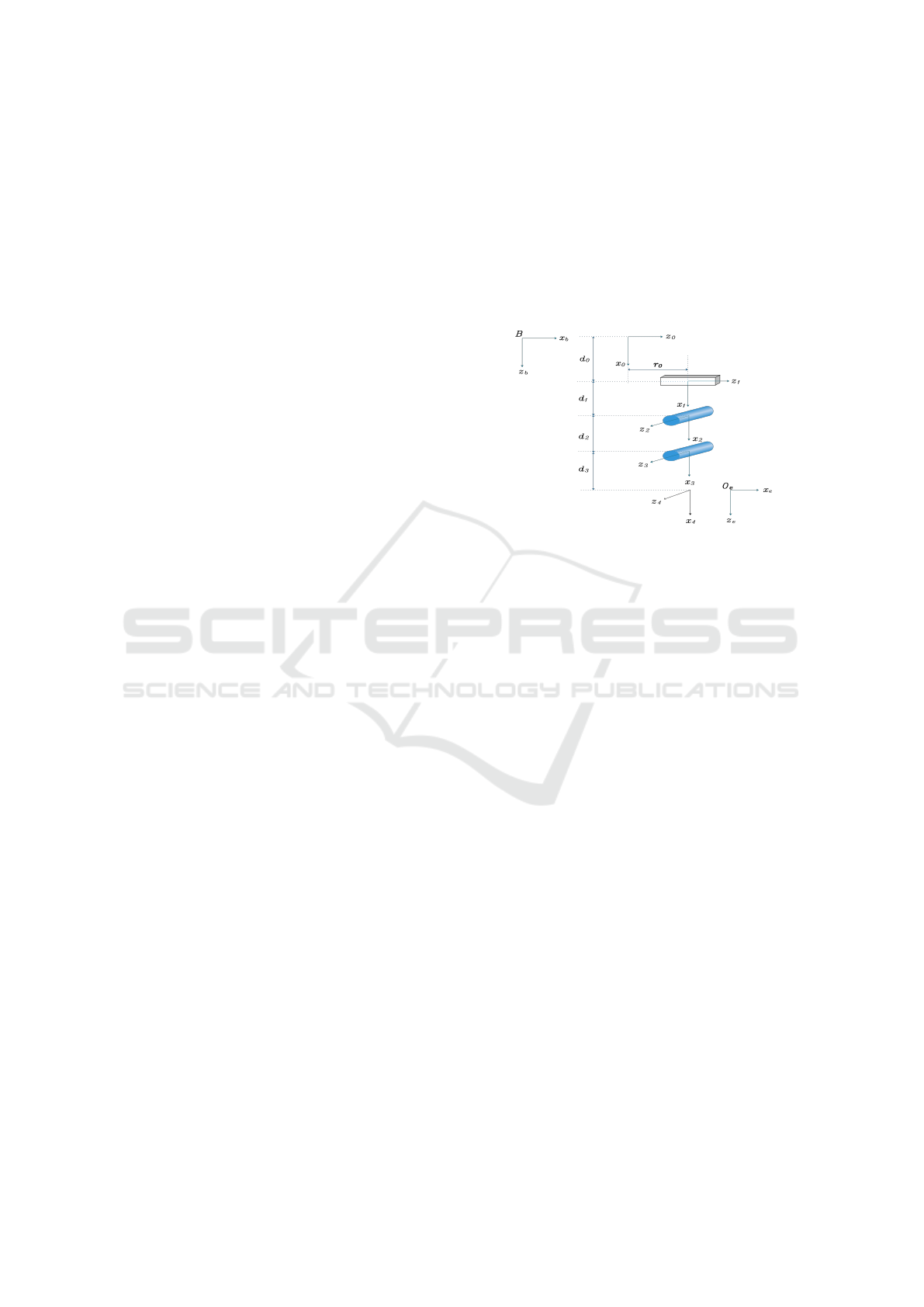
depicted in Figure (2).
Figure 2: The coordinate frame assignment of system.
3.1 Kinematics
The direct kinematic model (DK) consists to compute
the position and attitude of end-effector named op-
erational coordinates χ
e
=
p
T
e
ϕ
T
e
T
, when χ
e
is
the (6 × 1) vector describing the system configura-
tion of position and orientation with ϕ
e
is the end-
effector orientation expressed via Euler angles (roll-
pitch-yaw).
As a function of the generalized joint variables, χ
e
=
f (ξ):R
(6+n)
7−→ R
6
, where ξ is the (6 + n) vec-
tor of the generalized variables described as ξ =
q
T
b
q
T
eb
T
. Where q
b
, q
eb
present the joint vari-
ables of the end-effector and multirotor frame with
respect to
~
E and
~
B, are expressed as q
b
=
p
T
b
ϕ
T
b
T
and q
eb
=
q
1
... q
n
T
, respectively. Geometric
methods are used by some researches, when the D-H
method is used in this paper because of its recursive
compute for modeling of any number of joints and
links see (Siciliano et al., 2010). The DK is obtained
by simple products of the homogeneous transforma-
tion matrices A
i−1
i
(i = 1...n), from mobile frame
~
B to
the end-effector frame by:
A
e
= A
b
A
b
0
A
0
1
A
1
2
... A
n−1
n
A
n
e
(2)
where A
b
0
is a constant homogeneous transformation
describing the position and orientation of frame 0
of robot arm base with respect to the mobile frame
~
B, those transformation matrices are obtained by
using the Denavit-Hartenberg convention (Bouzgou
A Novel Aerial Manipulation Design, Modelling and Control for Geometric CoM Compensation
477
Table 1: Denavit-Hartenberg (D-H) parameters of Q-PRR.
i σ
i
α
i
d
i
θ
i
r
i
0 1 0 d
0
0 r
0
1 0 π d
1
θ
2
0
2 0 0 d
2
θ
3
0
3 0 0 d
3
0 0
and Ahmed-Foitih, 2014; Bouzgou et al., 2015)
and methodology, and are listed in Table (1). The
homogeneous matrix from the end-effector frame
with respect to
~
B frame is presented as:
A
b
e
=
c
23
0 s
23
r
0
+ d
2
s
2
+ d
3
s
23
0 1 0 0
−s
23
0 c
23
d
0
+ d
1
+ d
2
c
2
+ d
3
c
23
0 0 0 1
Where s
23
= sin(θ
2
+ θ
3
) and c
23
= cos(θ
2
+ θ
3
)
The position and orientation equations of end-effector
expressed in
~
E are written as follows:
p
e
= p
b
+ R
b
p
b
e
(3)
R
e
= R
b
.R
b
e
(4)
By denoting with
˙
ϕ
b
the time derivative of ϕ
b
.
ω
b
= T (φ
b
)
˙
ϕ
b
(5)
Where T (φ
b
) is the transformation matrix be-
tween the time derivative of the Euler angles ϕ
b
and
the angular velocity of the multirotor ω
b
.
T (φ
b
) =
1 0 −s
θ
0 c
φ
s
φ
c
θ
0 −s
φ
c
φ
c
θ
By differentiating (3), (4) and with taking into ac-
count (5), the translational and angular velocities of
the end-effector with respect to
~
E can be written as
follows:
˙p
e
= ˙p
b
− R
b
b
p
b
eb
T (φ
b
)
˙
ϕ
b
+ R
b
˙p
b
eb
(6)
ω
e
= T (φ
b
)
˙
ϕ
b
+ R
b
ω
b
eb
(7)
Where ˙p
b
,ω
b
are the linear and angular velocities
of the mobile frame
~
B with respect to the
~
E frame,
respectively, and ˙p
b
eb
,ω
b
eb
are the translational and an-
gular velocities of the end-effector with respect to the
mobile frame
~
B. (ˆ.) : R
3
−→ SO(3), the hat map that
transforms a vector in R
3
to (3 × 3) Skew-symmetric
matrix such that ˆxy = x × y, ∀x, y ∈ R
3
(Kamel et al.,
2017).
Let be v
b
eb
=
˙p
bT
eb
ω
bT
eb
T
the (6×1) vector of the
generalized velocity of the end-effector with respect
to
~
B, can be rewrite it in terms of ˙q
eb
via the jacobian
matrix J
b
eb
of the manipulator,
v
b
eb
= J
b
eb
(q
eb
) ˙q
eb
(8)
From 3 and 4 with the jacobian matrix equation 8, the
generalized velocity vector v
e
=
˙p
T
e
ω
T
e
T
, can be
expressed as
v
e
= J
b
T
A
(φ
b
) ˙q
b
+ J
eb
˙q
eb
(9)
Matrices J
b
and J
eb
are given by
J
b
=
I
3
−R
b
b
p
b
eb
0
3
I
3
, J
eb
=
R
b
0
3
0
3
R
b
J
b
eb
and T
A
(φ
b
) =
I
3
0
3
0
3
T (φ
b
)
J
eb
=
1 (d
2
c2 + d
3
c23) d
3
c23
0 0 0
0 −(d
2
s2 + d
3
s23) −d
3
s23
0 0 0
0 1 1
0 0 0
=
J
eb
p
J
eb
o
The existence of the inverse jacobian matrix is en-
sured when the end-effector avoids the set of singular
positions in the 2D plane, is that by the resolution of
det(J
eb
p
) = 0.
Therefore J
−1
eb
∗
exists if θ
2
6= kπ, this is the singular
position of the manipulator for the angles value θ
2
,
where joints velocity in the operational space can not
be ensured..
3.1.1 Inverse Kinematics
The inverse kinematics model consists the determina-
tion of joint variables required to achieve the given
end-effector position and orientation, as a function, it
can be written ξ = f (p
d
e
,R
d
e
), where p
d
e
, R
d
e
are the de-
sired position and orientation of end-effector, respec-
tively.
The position of the end-effector with respect to
~
B,
p
eb
∈ R
2
, when the position of the multirotor with re-
spect to the
~
E is described by
~
B, with p
b
∈ R
3
, their
workspaces is the disk for the robot arm, and a hemi-
sphere for UAV.
Ruggiero Fabio and co-workers in (Ruggiero et al.,
2015) are used a moving battery to counterweight the
statics of the robotic arm. However, its movement
can not be compensated if it moves will be faster than
15cm/s, when the battery servo is limited to πrad/s,
in addition the movement of the battery changes the
CoG position of UAV.
The structure of Q − PRR is designed that the dis-
placement of the arm does not change the CoG posi-
tion of the multirotor, and can only displace the CoG
of the system, in addition it can increase the linear ve-
locity of the system in the
~
b
2
, when the UAV and a
slider joint are moved at the same time.
ICINCO 2019 - 16th International Conference on Informatics in Control, Automation and Robotics
478
IK model computes the joint angles required to
achieve the given position and orientation IK does
not have a unique solution, the solutions which en-
sure collision avoidance, long battery life, minimum
joint motion, and low torque values generate by robot
arm applied on the multirotor, are considered more
optimum.
The kinematic inverse system is obtained by using the
pseudo-inverse of the matrix J presented in(Siciliano
et al., 2010), then J
†
= J
T
(J J
T
)
−1
.
The algorithm in (Arleo et al., 2013) is used, CLIKA:
Closed loop inverse kinematics algorithm we obtain:
˙
q
e
= J
†
( ˙x
e,d
− K e) (10)
With K is a symmetric positive definite gain matrix.
e = x
d
e
− x
r
e
, is the kinematic inversion error,we pre-
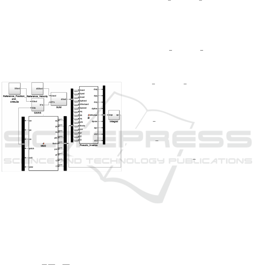
sented that in the Simulink block in Figure[3]
Figure 3: CLIKA Closed Loop Inverse Kinematic Algo-
rithm.
3.2 Dynamics Model
The dynamic model of Q-PRR can be derived by con-
sidering the Lagrange formulation in details in (Lip-
piello and Ruggiero, 2012). The function of La-
grangian is then expressed by L = E − U where E ,
U denote the kinematics and potential energy of the
whole system, respectively. The Lagrange equations
are given by
d
dt
δL
δ
˙
ξ
i
−
δL
δξ
i
= u
i
(11)
Where i = 1,...,6 + n is the i − th coordinate of ξ,
and u
i
is the ((6 + n) ×1) vector of generalized forces
and torques. The kinetic energy of the global system
expressed in
~
B frame is given by
E = E
b
+
n
∑
i=1
E
ci
(12)
Where E
b
is the kinetic energy of multirotor.
while E
ci
is the kinetic energy of the i link of manip-
ulator arm.
The kinematic energy of multirotor can be expressed
as
E
b
=
1
2
m
b
˙p
T
b
˙p
b
+
1
2
ω
T
b
R
b
I
b
R
T
b
ω
b
Where I
b
and m
b
are the inertia matrix and the mass of
the multirotor expressed with the respect to
~
B frame,
respectively. Taking into account that Q = R
T
b
T
b
, the
kinetic energy of multirotor can be rewritten on the
new form as
E
b
=
1
2
m
b
˙p
T
b
˙p
b
+
1
2
˙
ϕ
T
b
Q
T
I
b
Q
˙
ϕ
b
(13)
whereas, the kinetic energy of i−th link of the robotic
manipulator is given by
E
ci
=
1
2
m
ci
˙p
T
ci
˙p
ci
+
1
2
ω
T
ci
R
b
R
b
ci
I
i
ci
(R
b
ci
)
T
R
T
b
ω
ci
(14)
from (12), (13) and (14) we obtain the kinetic energy
of whole system and it can be written as,
E =
1
2
˙
ξ
T
m
Q
B
Q1
+
n
∑
i=1
m
ci
B
ci1
B
T
ci1
!
+
1
2
˙
ξ
T
B
Q2
I
Q
B
T
Q2
+
n
∑
i=1
B
ci2
I
i
ci
B
T
ci2
!
˙
ξ (15)
E =
1
2
˙
ξ
T
B
˙
ξ (16)
B is the (3 × 3) matrix of (3 × 3) inertia matrix ele-
ments, B ∈ M
(3×3)
and B
i j
∈ R
(3×3)
. For more details
see (Lippiello and Ruggiero, 2012).
The potential energy of the whole system es given by
the sum of that of the multirotor and that of each link
of the manipulator arm.
U = U
b
+
n
∑
i=1
U
ci
(17)
The potential energy of multirotor is given by
P
b
= m
b
ge
T
3
p
b
(18)
On the other hand, the potential energy of each link i
of manipulator is given by
U
ci
= m
ci
ge
T
3
(p
b
+ R
b
p
b
ci
) (19)
The total potential energy of overall system can be get
for a sum of (18) and (19) therefore:
U = m
b
ge
T
3
p
b
+
n
∑
i=1
m
ci
ge
T
3
(p
b
+ R
b
p
b
ci
) (20)
A Novel Aerial Manipulation Design, Modelling and Control for Geometric CoM Compensation
479
Where g = 9.8m/s
2
is the gravity acceleration value
and e
3
= [
0 0 1
] unit vector along z axis. Consid-
ering equations 12, 20 and 11, the dynamic model of
the global system can be written as
B(ξ)
¨
ξ + C(ξ,
˙
ξ)
˙
ξ + G(ξ) = u (21)
Where G is a ((6 + n) × 1) vector of gravitational
terms given by deriving the potential energy as
G(ξ) =
δP
δξ
And C is the matrix of Coriolis and cen-
trifugal terms given by
C
i j
=
6+n
∑
k=1
1
2
δb
i j
δξ
k
+
δb
ik
δξ
j
+
δb
jk
δξ
i
˙
ξ
k
Where b
i
j is the generic element of B, and u
i
is the
vector of generalized forces at the i −th joint level.
u =
u
f
b
u
τ
b
u
µ
=
R
b
f
b
R
T
b
T
b
τ
b
µ
=diag(R
b
,Q,I
n
)
f
b
=
0
0
f
bz
, τ
b
=
τ
φ
τ
θ
τ
ψ
, µ =
f
r
0
τ
θ
2
τ
θ
3
f
bz
τ
b
=
1 1 1 1
0 l 0 −l
−l 0 l 0
c −c c −c
f
1
f
2
f
3
f
4
Where l is the distance from each motor to the multi-
rotor centre of mass. When c is the drag factor.
4 CONTROLLER DESIGN
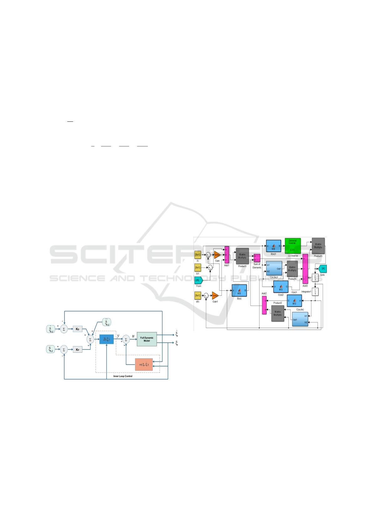
Figure 4: The control block diagram of Q-PRR.
Dynamic inversion control is an approach founded to
find a control vector u, as a function of the system
state, where a feedback linearisation loop is applied
to the tracking outputs of the desired values, usage re-
quires the selection of the output control variables.
The possibility of finding such a linearizing controller
is guaranteed by the particular form of system dynam-
ics.
Which is able to realize an input/output relationship
of linear type, in other words, we need to use an exact
linearization of system dynamics obtained by means
of a nonlinear state feedback instead of an approxi-
mate linearization.
The possibility of finding such a linearizing controller
is guaranteed by the particular form of system dynam-
ics.
In fact, the equation in 22 is linear in the control u and
has a full-rank matrix B(ξ) which can be inverted for
any manipulator configuration.
B(ξ)
¨
ξ + n(ξ,
˙
(ξ)) = u (22)
n(ξ,
˙
(ξ)) = C(ξ,
˙
(ξ))
˙
(ξ) + g(ξ)
The control vector is chosen as follow:
u = B(ξ)y + n(ξ,
˙
ξ) (23)
y =
¨
ξ
d
+ K
P
˜
ξ + K
D
˙
˜
ξ (24)
where y represents a new input vector
˜
ξ = ξ
d
− ξ and
˙
˜
ξ =
˙
ξ
d
−
˙
ξ, And K
P
and K
D
are diagonal matrices
with a positive gain. Two results to be compared
Figure 5: Block diagram of the proposed controller.
for a robot arm move to the desired position and in
the only one configuration, the first case is when the
multirotor is considered as in the stable situation,
torques and forces are neglected, for a desired
accuracy and position, the results are shown bellow
in Figures. Two scenarios are realized.
The first Fig. 6 , represents a static manipulator arm
and its goal is to let the multirotor reaching a desired
position. The second Fig. 7 represents a static
multirotor and its goal is to let the manipulator arm
reaching a desired position.
The robot design using SolidWorks and its all
parameters is presented in the table 2.
ICINCO 2019 - 16th International Conference on Informatics in Control, Automation and Robotics
480
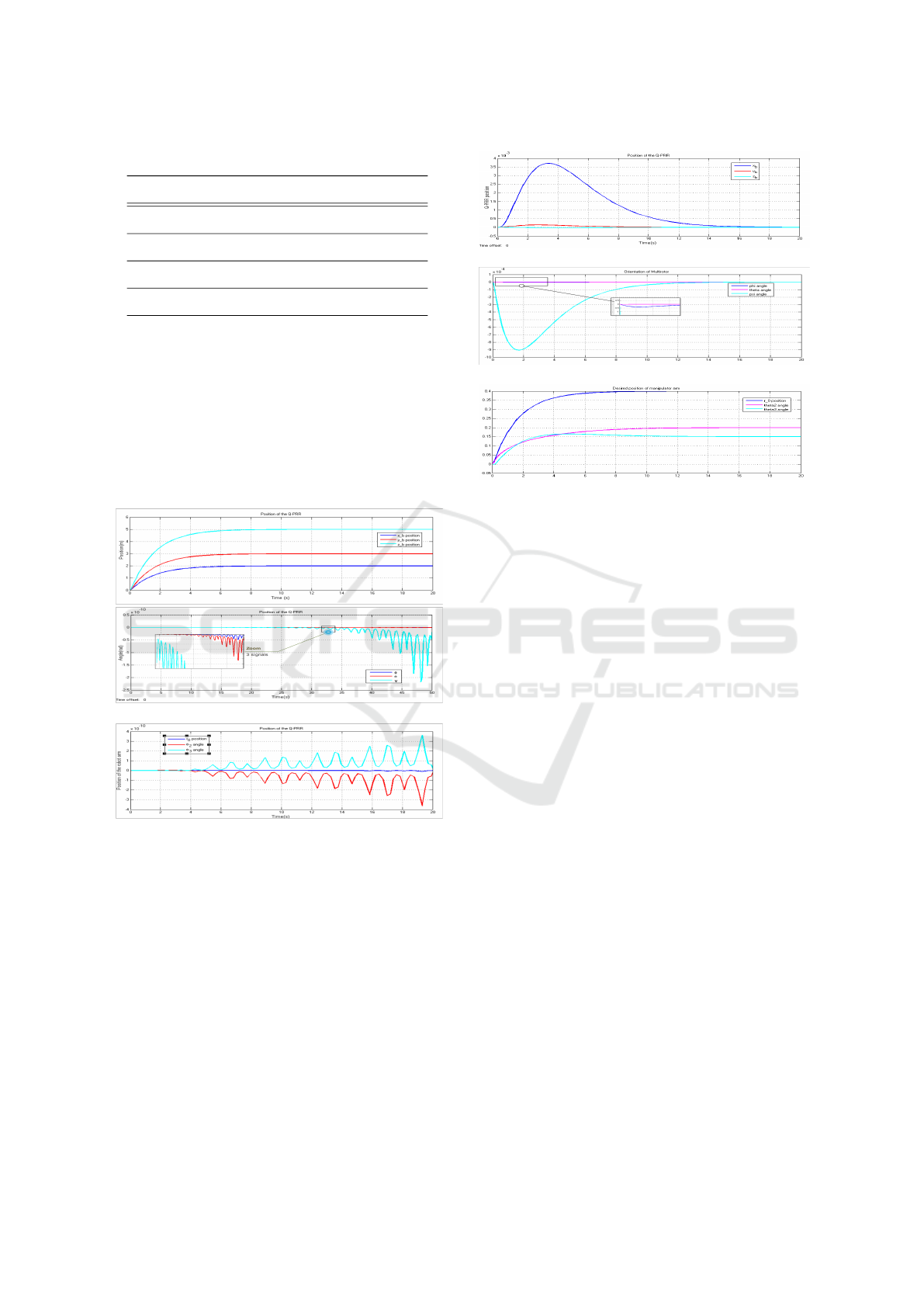
Table 2: Dynamic parameters of Links.
Link mass length I
xx
I
yy
I
zz
Base 11.29 20 1324.16 1674.01 2561.03
1 31.72 80 2283.37 19715.51 19807.8
2 17.73 180 280.23 50131.61 50133.13
3 9.61 95 206.92 7993.53 8059.21
Gains of controller using Simulink are chosen in
order to have not oscillations and to reach desired
values as soon as possible.
K
D
= 18 I
9
, K
P
= 30 I
9
,
x
i
= [0;0; 0; 0; 0; 0; 0.4; 0.2; 0.15],
˙x
i
= [0;0; 0; 0; 0; 0; 0; 0; 0],
x
i
= [2;3; 5; 0; 0; 0; 0; 0; 0],
˙x
i
= [0;0; 0; 0; 0; 0; 0; 0; 0].
Figure 6: 1 st scenario.
5 CONCLUSIONS
In this paper, we have formulated a mathematical
model for a whole system, (multirotor and robot
arm)via the Denavit-Hartenberg approach. The dy-
namic equation has been established according to the
Lagrange’s principle. The closed loop inverse kine-
matics algorithm is used and it was implemented in
the control design. An inverse dynamic control is de-
signed to achieve the desired performance for end ef-
fector target. Results show that torques and forces
generated by the multirotor can disturb a manipula-
tor motion, but the prismatic joint will work as an in-
Figure 7: 2 nd scenario.
stantaneous corrector on the stability of the system
without losing the correct configuration and without
affecting the desired target. Our future works will
present an another approach for a dynamic model
by using a SimMechanics and VRML environment
(Bouzgou et al., 2014).
REFERENCES
Arleo, G., Caccavale, F., Muscio, G., and Pierri, F. (2013).
Control of quadrotor aerial vehicles equipped with a
robotic arm. In Control & Automation (MED), 2013
21st Mediterranean Conference on, pages 1174–1180.
IEEE.
Aydemir, M., Arıkan, K. B., and
˙
Irfano
˘
glu, B. (2015). Dis-
turbance rejection control of a quadrotor equipped
with a 2 dof manipulator. In Machine Vision and
Mechatronics in Practice, pages 91–103. Springer.
Backus, S. B. and Dollar, A. M. (2017). Design optimiza-
tion of a prismatic-revolute-revolute joint hand for
grasping from unconstrained vehicles. In ASME 2017
International Design Engineering Technical Confer-
ences and Computers and Information in Engineering
Conference, pages V05BT08A002–V05BT08A002.
American Society of Mechanical Engineers.
Bouzgou, K. and Ahmed-Foitih, Z. (2014). Geometric mod-
eling and singularity of 6 dof fanuc 200ic robot. In
Innovative Computing Technology (INTECH), 2014
Fourth International Conference on, pages 208–214.
IEEE.
Bouzgou, K., Ahmed-Foitih, Z., and Oran-Algeria, U. M.
(2014). Singularity analysis and illustration of inverse
kinematic solutions of 6 dof fanuc 200ic robot in vir-
tual environment. Journal of Intelligent Computing,
5(3):91–105.
A Novel Aerial Manipulation Design, Modelling and Control for Geometric CoM Compensation
481

Bouzgou, K., Amar, R. H. E., and Ahmed-Foitih, Z. (2015).
Virtual reality simulation and singularity analysis of
3-rrr translational parallel robot. In Innovative Com-
puting Technology (INTECH), 2015 Fifth Interna-
tional Conference on, pages 61–66. IEEE.
Cho, S. and Shim, D. H. (2017). Development of a vision-
enabled aerial manipulator using a parallel robot.
Transactions of the Japan Society for Aeronautical
and Space Sciences, Aerospace Technology Japan,
15(APISAT-2016):a27–a36.
Dai, S., Lee, T., and Bernstein, D. S. (2014). Adaptive con-
trol of a quadrotor uav transporting a cable-suspended
load with unknown mass. In Decision and Control
(CDC), 2014 IEEE 53rd Annual Conference on, pages
6149–6154. IEEE.
Danko, T. W., Chaney, K. P., and Oh, P. Y. (2015). A parallel
manipulator for mobile manipulating uavs. In Tech-
nologies for Practical Robot Applications (TePRA),
2015 IEEE International Conference on, pages 1–6.
IEEE.
Danko, T. W. and Oh, P. Y. (2014). Design and control of
a hyper-redundant manipulator for mobile manipulat-
ing unmanned aerial vehicles. Journal of Intelligent &
Robotic Systems, 73(1-4):709.
Escareno, J., Flores, G., Rakotondrabe, M., Romero, H.,
Lozano, R., and Rubio, E. (2014). Task-based con-
trol of a multirotor miniature aerial vehicle having an
onboard manipulator. In Unmanned Aircraft Systems
(ICUAS), 2014 International Conference on, pages
857–863. IEEE.
Fumagalli, M., Naldi, R., Macchelli, A., Forte, F., Keemink,
A. Q., Stramigioli, S., Carloni, R., and Marconi,
L. (2014). Developing an aerial manipulator proto-
type: Physical interaction with the environment. IEEE
robotics & automation magazine, 21(3):41–50.
Huber, F., Kondak, K., Krieger, K., Sommer, D.,
Schwarzbach, M., Laiacker, M., Kossyk, I., Parusel,
S., Haddadin, S., and Albu-Sch
¨
affer, A. (2013). First
analysis and experiments in aerial manipulation us-
ing fully actuated redundant robot arm. In Intelligent
Robots and Systems (IROS), 2013 IEEE/RSJ Interna-
tional Conference on, pages 3452–3457. IEEE.
Jimenez-Cano, A., Heredia, G., and Ollero, A. (2017).
Aerial manipulator with a compliant arm for bridge
inspection. In Unmanned Aircraft Systems (ICUAS),
2017 International Conference on, pages 1217–1222.
IEEE.
Kamel, B., Yasmina, B., Laredj, B., Benaoumeur, I., and
Zoubir, A.-F. (2017). Dynamic modeling, simulation
and pid controller of unmanned aerial vehicle uav. In
Innovative Computing Technology (INTECH), 2017
Seventh International Conference on, pages 64–69.
IEEE.
Kim, S., Choi, S., and Kim, H. J. (2013). Aerial ma-
nipulation using a quadrotor with a two dof robotic
arm. In Intelligent Robots and Systems (IROS), 2013
IEEE/RSJ International Conference on, pages 4990–
4995. IEEE.
Kondak, K., Krieger, K., Albu-Schaeffer, A., Schwarzbach,
M., Laiacker, M., Maza, I., Rodriguez-Castano, A.,
and Ollero, A. (2013). Closed-loop behavior of an
autonomous helicopter equipped with a robotic arm
for aerial manipulation tasks. International Journal of
Advanced Robotic Systems, 10(2):145.
Korpela, C., Orsag, M., Pekala, M., and Oh, P. (2013). Dy-
namic stability of a mobile manipulating unmanned
aerial vehicle. In germany 2013, I., editor, Robotics
and Automation (ICRA), 2013 IEEE International
Conference on, pages 4922–4927. IEEE.
Lipiello, V. and Ruggiero, F. (2012). Exploiting redundancy
in cartesian impedance control of uavs equipped with
a robotic arm. In RSJ International Conference on
Intelligent Robots and Systems, pages 3768–3773.
Lippiello, V. and Ruggiero, F. (2012). Cartesian impedance
control of a uav with a robotic arm. IFAC Proceedings
Volumes, 45(22):704–709.
Mello, L. S., Aldorno, B., and Raffo, G. V. (2015). Whole-
body modeling and control of an unmanned aerial ma-
nipulator. In the XII Brazilian Symposium of Intelli-
gent Automation (XII SBAI). Natal.
Mersha, A. Y., Stramigioli, S., and Carloni, R. (2014). Ex-
ploiting the dynamics of a robotic manipulator for
control of uavs. In Robotics and Automation (ICRA),
2014 IEEE International Conference on, pages 1741–
1746. IEEE.
Orsag, M., Korpela, C., and Oh, P. (2013). Modeling and
control of mm-uav: Mobile manipulating unmanned
aerial vehicle. Journal of Intelligent & Robotic Sys-
tems, pages 1–14.
Ruggiero, F., Trujillo, M. A., Cano, R., Ascorbe, H., Vig-
uria, A., Per
´
ez, C., Lippiello, V., Ollero, A., and Si-
ciliano, B. (2015). A multilayer control for multirotor
uavs equipped with a servo robot arm. In Robotics and
Automation (ICRA), 2015 IEEE International Confer-
ence on, pages 4014–4020. IEEE.
Siciliano, B., Sciavicco, L., Villani, L., and Oriolo, G.
(2010). Robotics: modelling, planning and control.
Springer Science & Business Media.
Srikanth, M. B., Soto, A., Annaswamy, A., Lavretsky, E.,
and Slotine, J.-J. (2011). Controlled manipulation
with multiple quadrotors. In AIAA Conf. on Guidance,
Navigation and Control.
Yeol, J. W., Toohey, D., and Hwang, Y.-W. (2017). Design
and analysis of a multiple tentacle system for mobile
manipulation in micro aerial vehicles. Procedia Com-
puter Science, 105:7–13.
ICINCO 2019 - 16th International Conference on Informatics in Control, Automation and Robotics
482
