
A Fuzzy Inference Approach to Control Robot Speed in Human-robot
Shared Workspaces
Angelo Campomaggiore, Marco Costanzo, Gaetano Lettera and Ciro Natale
Dipartimento di Ingegneria, Universit
`
a degli Studi della Campania ”Luigi Vanvitelli”, Via Roma 29, Aversa, Italy
Keywords:
Human-robot Collaboration, Workspace Monitoring, Fuzzy Logic.
Abstract:
Nowadays, human-robot collaboration (HRC) is an important topic in the industrial sector. According to the
current regulations, the robot no longer needs to be isolated in a work cell, but a collaborative workspace in
which human operators and robots coexist can be acceptable. Human-robot interaction (HRI) is made possible
by proper design of the robot and by using advanced sensors with high accuracy, which are adopted to monitor
collaborative operations to ensure the human safety. Goal of this article is to implement a fuzzy inference
system, based on the ISO/TS 15066, to correctly compute the minimum protective separation distance and
adjust the robot speed by considering different possible situations, with the aim to avoid any collisions between
operators and robots trying to minimize cycle time as well.
1 INTRODUCTION
The research paper tackles the human-robot collab-
oration problem by following the line of the current
regulations and introducing a new approach to be used
in manufacturing industry. The novel method assures
human operators safety, without modifying the robot
predefined path and defining a safety metric to scale
robot trajectory only when indispensable, thus trying
to maximize the production time.
The research work is carried out in the framework
of a European project (The LABOR project, 2019),
which has the objective to propose novel robotized
assembly paradigms of aircraft fuselage panels. Un-
til recently, the aerospace industry was still conserva-
tive and companies tended to use successful assem-
bly methods that had already been proven to work in
the past. Nowadays, many assembly sub-operations
try to exploit robotics, e.g., drilling, fastening and
sealing tasks. These operations are no longer man-
ually performed by human operators but by industrial
robots equipped with dedicated tools or by large au-
tomated machines dedicated to assembly of specific
parts. However, there are some detailed operations
which require human capabilities and that must be
still executed by operators. This is the case of hy-
brid metal and composite structures, where, after the
drilling operation, some parts have to be manually re-
moved for further manual operations, like deburring,
and then re-installed on the skin panel before the seal-
ing and riveting operations, as shown in Figure 1.
This requires to setup a robotic cell that has to
foresee the presence of a human operator, hence the
necessity to monitor the shared workspace. Real-time
workspace monitoring for human-robot coexistence is
not an easy problem to solve. Even more, implement-
ing strategies to maximize the production time and
preserve human safety at the same time is a research
challenge. The approach proposed here is to adopt
a fuzzy inference logic that can update the planned
robot velocity in real-time according to robust per-
ception data and a set of rules formulated based on
a risk analysis. This can lead to a novel, acceptable
solution.
Ensuring the safety of a human operator is the
main purpose of the current research of industrial col-
laborative robotics. The safety standards for appli-
cations of industrial robots are laid out by the Inter-
national Organization for Standardization (ISO) (ISO
10218-1, 2011), (ISO 10218-2, 2011), and by the up-
coming ISO proposed draft Technical Specification
(TS) (ISO/TS 15066, 2016), which addresses four
collaborative scenarios:
1. Safety-rated Monitored Stop (SMS), which re-
quires that the robot stops when a human is in the
collaborative workspace;
2. Hand Guiding (HG), which allows the operator
to hand-guide the robot through an hand guiding
equipment (e.g., an analog button cell attached to
78
Campomaggiore, A., Costanzo, M., Lettera, G. and Natale, C.
A Fuzzy Inference Approach to Control Robot Speed in Human-robot Shared Workspaces.
DOI: 10.5220/0007838700780087
In Proceedings of the 16th International Conference on Informatics in Control, Automation and Robotics (ICINCO 2019), pages 78-87
ISBN: 978-989-758-380-3
Copyright
c
2019 by SCITEPRESS – Science and Technology Publications, Lda. All rights reserved

the robot) and an emergency stop conforming to
International Electrical Commission (IEC) (IEC
60204-1, 2009);
3. Speed and Separation Monitoring (SSM), which
monitors the robot speed according to the separa-
tion distance from the operator;
4. Power and Force Limiting (PFL), which limits the
momentum of the robot such that the potential
for operator injury upon impact is minimized, ac-
cording to the established injury standards (Bicchi
et al., 2008).
In this paper, a strategy to handle the operators
safety in industrial SSM scenarios is investigated.
The main goal is to reasonably scale down the size
of the protective zone around the robot and improve
productivity, taking into account safety regulations.
The robot behavior is modified, in terms of trajec-
tory scaling, only if there is a real and imminent
risk of collision. The operator approach into the col-
laborative workspace is deeply analyzed to general-
ize the computing method of the safety index and
face the extreme variability and unpredictability of
human behaviours. The devised solution computes
the points at minimum distance between the robot
and the closest human and presents several desir-
able features with respect to other solutions, e.g.,
(Zhang et al., 2016),(Bascetta et al., 2011),(Lippi and
Marino, 2018),(Bjerkeng et al., 2014); many of these
approaches rely on evasive actions to increase safety.
However, in industrial setting, it is generally recom-
mended to follow the robot predefined path without
deviating from it, especially in complex work cells,
where clashes are likely to occur. The main charac-
teristics of the proposed approach are:
• it considers the whole surface of human opera-
tors, without using skeleton-based techniques and
without approximating the body to a single point;
• it considers the whole robot kinematic chain, the
entire volume and possible tools, without factor-
ing only a singular representative element of the
robot (e.g., the end effector);
• it explicitly takes into account the regulations;
• it predicts the human velocity v
H
, by estimating
it from perception data without assuming it con-
stant;
• it is based on a risk analysis that considers the rel-
ative directions of velocities, which are not taken
into account in the equation proposed by the cur-
rent regulations;
• it does not modify the robot programmed path and
it does not require the task to be aborted.
Figure 1: Example of a manual assembly operation where
the operator shares the workspace with a robot.
2 ISO ANALYSIS: SSM
SSM allows the robot system and the operator to
move concurrently in the collaborative workspace.
Risk reduction is achieved by maintaining at least the
minimum protective separation distance, S, between
the human operator and the robot all the time. Dur-
ing robot motion, the robot system never gets closer
to the operator than S. When the Euclidean separation
distance, d, is equal to or less than S, the robot system
stops, before it can impact the operator. When the op-
erator moves away from the robot system, the robot
system can resume the motion automatically while
maintaining at least the protective separation distance.
(ISO 13855, 2010) is the first document which in-
vestigates the issue of safeguards positioning for hu-
man safety in stationary, active machinery. The docu-
ment suggests to compute S as
S = vT +C, (1)
where v is the approach speed of human body parts
and its value is assumed to be as the maximum opera-
tor speed of 2.0m/s, unless d is greater than 0.5 m, in
which case may be set at 1.6 m/s. T is the total sys-
tem stopping performance time, in seconds, and it is
a combination of the time required by the machine to
respond to the operator’s presence (i.e., T
R
) and the
response time of the machine which brings the robot
to a safe, controlled stop (i.e., T
S
). C is the intrusion
distance safety margin, which represents an additional
distance, based on the expected intrusion toward the
critical zone prior to the actuation of the protective
equipment.
From eq. (1), ISO/TS 15066 updates the S mean-
ing by including robot dynamic properties. When
the robot system reduces its speed, the protective
separation distance decreases correspondingly, i.e.,
A Fuzzy Inference Approach to Control Robot Speed in Human-robot Shared Workspaces
79

S(t
0
) ≥
Z
τ=t
0
+T
R
+T
S
τ=t
0
v
H
(τ)dτ +
Z
τ=t
0
+T
R
τ=t
0
v
R
(τ)dτ
+
Z
τ=t
0
+T
R
+T
S
τ=t
0
+T
R
v
S
(τ)dτ + (C + Z
S
+ Z
R
)
(2)
In (2), v
H
is the “directed speed” of the closest op-
erator which travels toward the robot, v
R
is the speed
of the robot in the direction of the operator, v
S
is the
directed speed of the robot in course of stopping. The
remaining terms represents uncertainties: the intru-
sion distance C is based on the operator reach, Z
R
is
the robot position uncertainty, and Z
S
is the operator
position uncertainty (i.e., the sensor uncertainty). Fi-
nally, t
0
is considered the current time.
The main issue of (ISO 13855, 2010) is that
the separation distance was initially intended for
static machinery, not for dynamic and reconfigurable
robotic systems. Therefore, extending what is con-
tained in the standard to the case of industrial robotics
is not trivial. Nevertheless, ISO/TS 15066 tries to
make a contribution to the HRC problem and de-
scribes S using the linear function
S = (v
H
T
R
+ v
H
T
S
) + (v
R
T
R
) + (B) + (C + Z
S
+ Z
R
)
(3)
where B is the Euclidean distance travelled by the
robot while braking. Note the one-to-one correlation
between eq. (2) and the linear relationship (3). The
first term in parentheses describes the contribution at-
tributable to the operator’s change in location in the
time necessary to bring the robot to a full stop from its
current speed. The second term describes the contri-
bution attributable to the robot system reaction time,
before it initiates the braking sequence. The third
term describes the distance travelled by the robot dur-
ing its braking. Finally, the fourth term describes the
possible distance of intrusion into the robot work vol-
ume as a function of the operator reach and the un-
certainty of the sensory system and robot kinematics.
The values of v
H
, T
S
, B and C can be found in the
safety standards: the values of v
H
and C are given in
ISO 13855, while guidelines for evaluating T
S
and B
are given in Annex B of ISO 10218-1 and they result
from measurements that directly depend on the robot
system under test.
This paper decomposes and assesses the perfor-
mance of ISO/TS 15066 SSM minimum protective
distance metric and adds a contribution to improve
some aspects to allow its applicability in industrial
scenarios. The following sections widely discuss
four main areas that are directly pertinent to SSM:
human detection and tracking, prediction of human
and robot motions, safety separation maintenance and
robot speed monitoring.
3 HUMAN-ROBOT
INTERACTION
The robot control system must be able to adapt the
robot trajectory to the current observed scene and to
perform its task efficiently and safely. This means
that the control system must be able to detect the
presence of human operators inside the collaborative
workspace, to track the human closest to the machine
and, finally, to modulate the robot speed according to
the minimum protective distance S.
The HRC has been addressed dividing it into
two distinct problems: human detection and tracking
(HDT) and intention estimation (IE).
3.1 Perception System
The experimental set-up of this work is composed by
two depth cameras, which have been used to monitor
the collaborative workspace: a Microsoft Kinect v1
and an Intel RealSense D435 (see Figure 2a). At least
two views become necessary to minimize the occlu-
sions of the observed area, as shown in Figure 2b and
Figure 2c.
An intrinsic calibration is necessary to update
the rough intrinsic default parameters, as well as, a
sphere-tracking procedure has been developed for ex-
trinsic calibration. The obtained homogeneous trans-
formation matrices, T
robot
camera1
and T
robot
camera2
, express the
poses of the camera frames with respect to the robot
base frame.
The goal of the extrinsic calibration is to obtain
an accurate identification of the camera pose, which
guarantees the minimum relative positioning error
when the two camera views are merged.
Therefore, a 3D tracking technique has been de-
veloped by using a polystyrene sphere of 0.12 m di-
ameter. The red sphere has been mounted at the
robot end effector, so as to match the center of the
sphere with the origin of the end-effector frame, as
shown in Figure 2. The calibration procedure uses
the M-estimator SAmple Consensus (MSAC) algo-
rithm (Torr and Murray, 1997) (which is an exten-
sion of the best known RANdom SAmple Consensus
(RANSAC) algorithm (Fischler and Bolles, 1981)), to
find a sphere within a radius constraint, and to provide
its geometric model. The robot has been positioned
at specific configurations, which allow to correctly
distinguish the target within the two camera views.
From the robot joint states, the forward kinematics
computes the pose of the center of the red sphere. At
the same time, the developed procedure acquires the
depth images, converts them into point clouds (Rusu
and Cousins, 2011) and estimates the target model.
ICINCO 2019 - 16th International Conference on Informatics in Control, Automation and Robotics
80
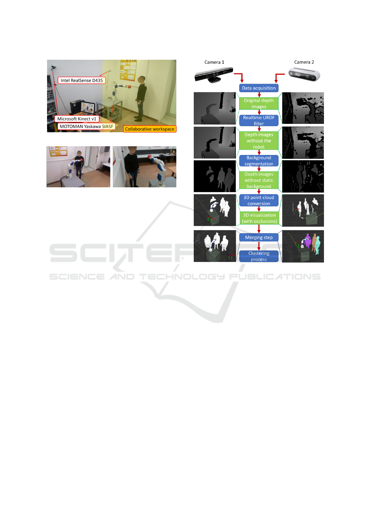
(a) Perception system.
(b) Kinect RGB view. (c) RealSense RGB view.
Figure 2: Experimental set-up.
The method is iterated to cover the entire collabora-
tive workspace and to minimize the positioning error.
Finally, the transformation matrices have been eval-
uated through an optimization algorithm with a cost
function that combines the data of both cameras.
3.2 Human Detection and Tracking
Realizing a safe HRC application requires a very fast
HDT algorithm, which detects human operators in
real time. In this study, a novel point cloud-based
methodology is presented to compute the minimum
distance between the whole body of the detected op-
erators and a robot. Since this operation is computa-
tionally heavy, a Background Segmentation (BS) al-
gorithm is developed to subtract the static environ-
ment from the observed scene and to process exclu-
sively the information related to the dynamic objects.
The developed pipeline is shown in Figure 3.
The perception system described in Section 3.1
observes the surroundings of the manipulator and the
robot kinematic chain is fully visible. While the
workspace is monitored, the robot executes its task,
thus it becomes a dynamic entity. Therefore, the Re-
altime URDF Filter (Blodow, 2012) is used to remove
the robot from the scene.
The implementation of the BS step consists of an
efficient algorithm that performs the subtraction of a
stored background, at pixel level: 50 frames of a static
scene in the absence of human workers are initially
captured and the mean value of each pixel is stored in
a memory area. Therefore, the stored frame is sub-
tracted from the current frame at every acquisition.
Figure 3: Implemented HDT pipeline.
The algorithm makes use of PCL: the depth in-
formation is converted into Point Cloud Data (PCD)
and a uniform sampling filter can be applied to make
the algorithm more reactive, by decreasing the PCDs
density.
Subsequently, a reference camera has been se-
lected to express the entire output of the perception
system relative to a single camera frame, in this case,
the Kinect camera. The point clouds have been com-
bined through the merging step (MS). The accuracy
reached during the extrinsic calibration procedure, de-
scribed in Section 3.1, allowed to obtain a satisfying
correspondence.
Finally, the clustering process (CP) provides as
many clusters as single dynamic areas are detected
in the foreground. The Euclidean cluster extraction
method is performed to highlight all the human clus-
ters of the collaborative workspace. The bottom right
image of Figure 3 shows three detected human op-
erators, whose shapes are distinguishable by different
colors. To compensate the sensors measurement noise
that could sometimes provide false clusters, the areas
in the foreground should be large enough to represent
a human body. Therefore, a valid cluster should have
A Fuzzy Inference Approach to Control Robot Speed in Human-robot Shared Workspaces
81
a minimum PCD cardinality, empirically determined.
3.3 Human-robot Separation Distance
The goal of the proposed HRC strategy is to identify
the nearest pair of points, one belonging to the robot
(P
R
) and the other one belonging to the operator (P
H
),
that minimize the distance, i.e.,
P
H
∈ H , P
R
∈ R | d(P
H
, P
R
) ≤ d(P
0
H
, P
0
R
)
∀P
0
H
∈ H , P
0
R
∈ R
(4)
where d(·, ·) is the Euclidean distance between two
points, H and R represent the set of all points that
belong to the operator and to the robot, respectively.
Therefore, alongside the HDT strategy, a robot
modeling method has been also implemented. To the
best of authors knowledge, the typical SoA assump-
tion is to consider only a representative elements of
the robot (e.g., the end effector), introducing only an
approximate estimation of the distance between the
operators and the robot kinematic chain. Other so-
lutions report the pose of the robot only in terms of
either joint configurations or in terms of the Carte-
sian pose of the robot link frames, without taking
into account the link shapes but considering only spe-
cific points. On the contrary, the proposed solution
models the entire robot kinematic chain with its vol-
ume. A computationally efficient way to represent
the whole robot is to use primitive shapes, e.g., el-
lipses and spheres (Choi and Kim, 1999). A simi-
lar convention was proposed in (Bosscher and Hed-
man, 2009) . This work is inspired by the same idea,
but pays attention to some aspects: since the robot
links can have different lengths, its kinematic chain
has been padded through dummy frames to protect
the robot homogeneously, and a 0.10m diameter se-
curity sphere has been created around each frame, tak-
ing into account the last frame that can incorporate an
end-effector tool.
Under such assumptions, the pair of human-robot
points that are closest to each other can be immedi-
ately identified. This step strongly justifies the choice
of a point cloud-based pipeline. In fact, the point
cloud provides much more detailed information, ac-
curacy and precision if compared to the major HDT
techniques present in the SoA literature cited in Sec-
tion 1. Unlike common skeleton-based techniques,
the proposed approach allows tracking humans also
when they are carrying objects. Moreover, it is not
necessary that human operators are in front of the
camera view: the point cloud will recognize them
anyway. Furthermore, detecting the pair of human-
robot points at minimum distance (4) is particularly
immediate. The algorithm calculates the distance be-
tween all points of a cluster point cloud and the origin
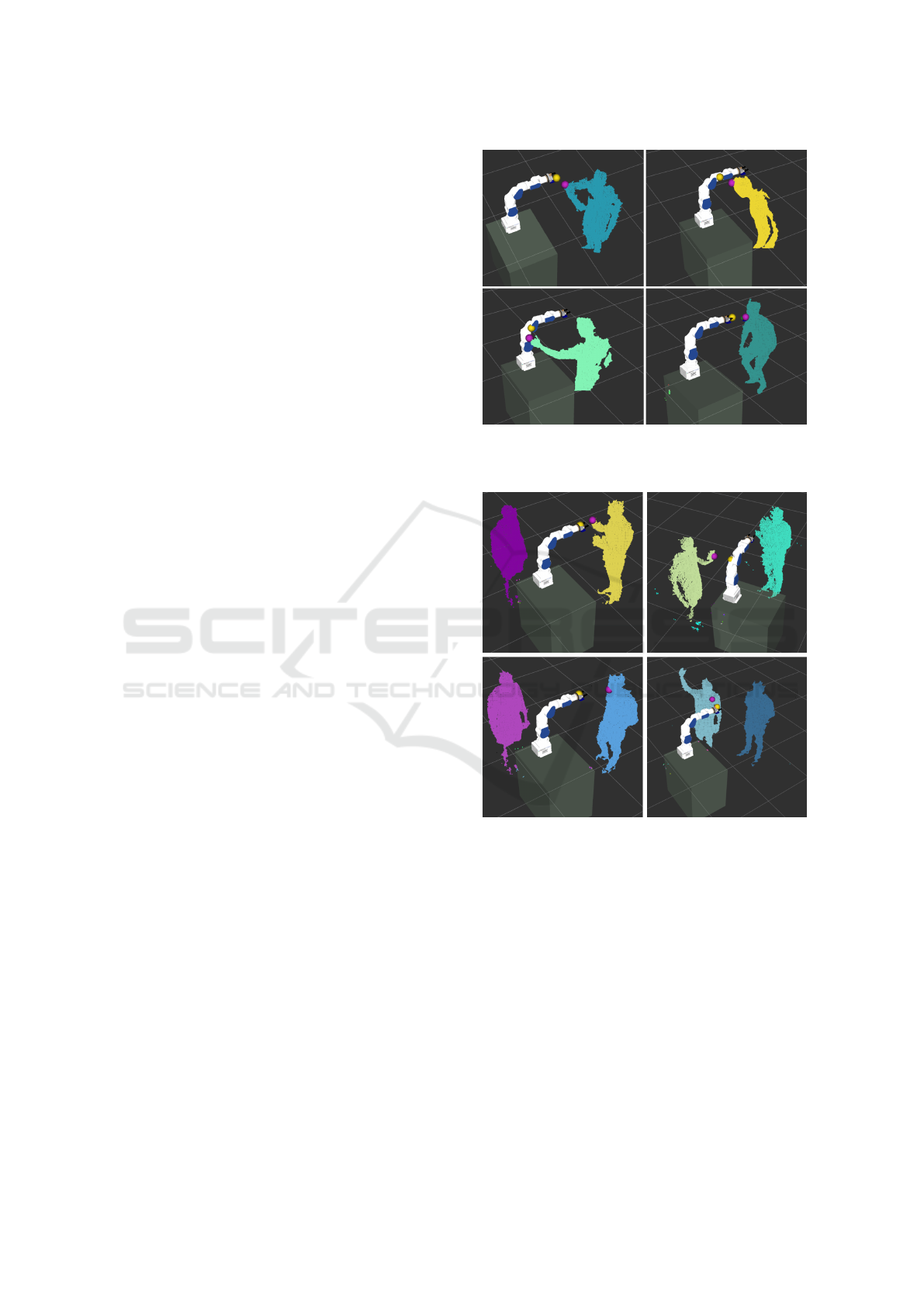
Figure 4: Identification of the minimum distance points: the
yellow sphere is the robot point closest to the human and the
purple one is the human point closest to the robot.
Figure 5: Multi-humans tracking.
of every robot frame. Eventually, the robot point P
R
will be the one on the surface of the virtual sphere,
around the identified frame, which lies on the line
connecting the origin of this frame and the closest
point in the cluster. From these results, the closest
human cluster is indirectly selected if more than one
human have been detected.
Figure 4 shows the results. Note that the proposed
approach is able to identify more detailed body parts,
e.g., a elbow, the head, an hand, the chin or the chest,
and also that P
R
can be detected along the whole robot
kinematic chain. Figure 5 demonstrates the effective-
ness of the proposed approach in multi-humans sce-
narios. The results of the experimental tests described
in Section 6 will be used to evaluate the performances
ICINCO 2019 - 16th International Conference on Informatics in Control, Automation and Robotics
82

of the algorithm.
3.4 Estimation of Operator and Robot
Velocities
Another fundamental function of the HRC problem is
represented by IE, i.e., the prediction of human move-
ment. From such information, the robot control sys-
tem will select the most appropriate value of its joint
speeds to avoid a potentially dangerous situation, as
explained in Section 5.
IE consists in estimating the next position and ve-
locity of the trajectory performed by the operator on
the basis of a series of positions previously acquired.
The sensor fusion strategy that has been integrated
into this work is based on a Linear Kalman Filter
(LKF), which tries to solve the problem of estimat-
ing the state of a discrete-time process governed by
the equations
x
k+1
=
I
3
∆tI
3
O
3
I
3
x
k
+ w
k
, (5)
y
k
=
I
3
O
3
x
k
+ n
k
(6)
where ∆t is the sampling time, I
3
and O
3
are the iden-
tity and zero matrices of size 3 × 3, respectively; w
and n are the process and measurement noises with
covariance matrices W and N , respectively. Finally,
x is the state vector of the system, i.e., the posi-
tion and the velocity of the operator x =
p
T
H
˙p
T
H
T
,
and the measured output y is a vector containing
the coordinates of the point P
H
described in Sec-
tion 3.3. The covariance matrix N is experimentally
estimated, while the covariance matrix Q has been
chosen as
Q =
I
3
∆t
2
O
3
O
3
Q
2
(7)
where Q
2
quantifies the uncertainty on the velocity
dynamics (assumed constant) of the state equations.
Based on the vector nature of the velocity, it is
possible to make some considerations about the di-
rection (trend) of the operator, that is to say, to predict
in which direction he/she is travelling to. Section 4
describes how to take advantage from these consid-
erations for industrial collaborative applications with
the aim to maximize productivity.
The LKF equations implemented in this work are
the standard ones and thus are not reported for brevity,
while the tuned parameters are fully described in Sec-
tion 6.
Figure 6 shows sample movements of the operator
and the three components of his/her estimated speed.
The linear velocity ˙p
R
of the point on the robot
closest to the operator can be computed according to
Figure 6: Estimation of operator velocity.
the differential kinematics equation
˙p
R
= J
p
(q) ˙q, (8)
where q [rad] and ˙q [rad/s] are the robot joint posi-
tion and velocity vectors, respectively; while, J
p
is
the position part of the Jacobian matrix calculated till
the closest point.
The (ISO/TS 15066, 2016) states that the “di-
rected speeds” of the robot and the human should be
used to compute S. This means that, in eq. (3), v
h
is
the operator speed in the direction of the moving part
of the robot and v
R
is the robot speed in the direction
of the selected operator. Note also that these speeds
are vector magnitudes, hence they are always grater
or equal to 0. Therefore, the velocity terms of (3) can
be computed as
v
H
=
˙
ˆp
T
H
p
R
− ˆp
H
k
p
R
− ˆp
H
k
(9)
v
R
=
˙p
T
R
ˆp
H
− p
R
k
ˆp
H
− p
R
k
, (10)
where ˆp
H
and
˙
ˆp
H
are the operator position and ve-
locity estimated by the LKF, respectively, and p
R
is a
vector containing the coordinates of the point P
R
de-
fined in Section 3.3.
4 FUZZY INFERENCE SYSTEM
The protective separation distance S in (3), computed
by using the speeds of (9)–(10), does not take into ac-
count the relative travel direction of the robot and the
operator. This means that, if the robot and the opera-
tor are going away from each other, the value of S un-
necessarily increases (proportionally to the computed
speed). To improve the production time considering
also this situation, the protective separation distance
has been redefined as follows
S = α[(v
H
T
R
+v
H
T
S
)+(v
R
T
R
)]+(B)+(C +Z
S
+Z
R
),
(11)
where α is a coefficient in the interval [0, 1] that is
1 when the operator and the robot are actually ap-
proaching to each other and is smaller than 1 other-
wise.
A Fuzzy Inference Approach to Control Robot Speed in Human-robot Shared Workspaces
83
To chose the value of α, a fuzzy inference ap-
proach has been implemented. The fuzzy logic, also
called faded logic, is a methodology in which each
proposition possesses a degree of truth into the inter-
val [0, 1] (Ross, 2010). The variable α must be clas-
sified taking into account some qualitative attributes
and it may have varying levels of validity between a
maximum (1) and a minimum (0). Hence, it is neces-
sary to generate linguistic rules of fuzzy inference to
realize a mapping of the inputs to the desired output.
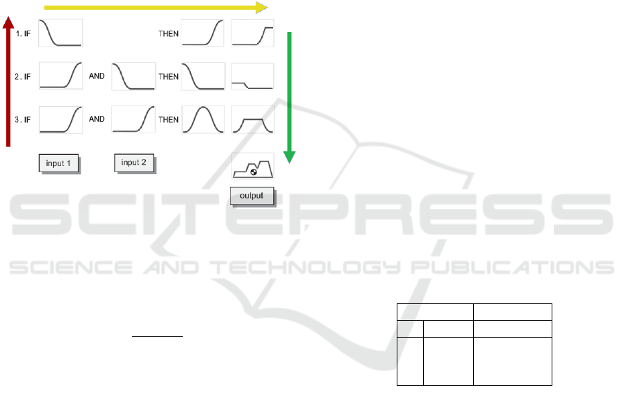
The fuzzy inference process has been developed
as a two-input, one-output, three-rule problem, as
shown in Figure 7.
Figure 7: Fuzzy inference system: the fuzzification step
(red arrow), the implication step (yellow arrow) and the ag-
gregation step (green arrow).
The first step is to select the inputs. Two data in-
puts have been selected:
1. the time derivative of the distance between human
and robot, i.e.,
˙
d =
d
k
ˆp
H
−p
R
k
dt
;
2. the scalar product between the robot and the hu-
man velocity vectors, i.e., ˙p
T
R
˙
ˆp
H
.
The first input is useful to distinguish cases when the
operator and the robot are getting closer and cases
when they are moving away from each other. The
scalar product specifies the relative direction of travel
of the operator and the robot.
The next step is the fuzzification step (red arrow
of Figure 7). The ranges of variability of each input
have been defined, and the appropriate membership
function of each interval has been selected. This step
requires attention to correctly determine the degree
to which the input belongs to each of the appropriate
fuzzy set, by assigning a fuzzy degree of membership
in the interval from 0 to 1. Two membership functions
have been selected to represent positive (P) and nega-
tive (N) values, a Z-shape and a S-shape, respectively.
These functions, with different parameters, have been
chosen to describe both ˙p
T
R
˙
ˆp
H
and
˙
d.
After the inputs are fuzzified, the implication step
(yellow arrow of Figure 7) determines the degree to
which each part of the antecedent is satisfied for each
rule. The antecedent of the developed fuzzy infer-
ence rules has three parts, combined through an AND
method (min) to obtain an implicated number that rep-
resents the result of the rule antecedent. Each rule is
designed to consider one possible risk scenario.
Since the final decision is based on the result of
all the tested rules, the outputs of the rules must be
combined in some way. The aggregation step (green
arrow of Figure 7) is the process by which the fuzzy
sets representing the outputs of each rule are com-
bined into a single fuzzy set, before the last defuzzifi-
cation step. For each interval of the consequent, the
maximum value of the fuzzy set is chosen and the de-
fuzzification method is the centroid, as shown at the
end of Figure 7.
The output value, α, has been generated by an-
alyzing different possible risk situations, with the
twofold aim of avoiding any collisions between hu-
man and robot, and being in line with the current
ISO/TS 15066. With reference to the second rule: if
the human-robot distance is increasing and they are
moving further from each other, than the safety dis-
tance can be decreased. The three rules are summa-
rized in Table 1.
Table 1: Fuzzy rules: [S] Small, [M] Medium, [H] High,
[N] Negative, [P] Positive, [∼] any.
antecedent consequent
˙
d ˙p
T
R
˙
ˆp
H
α
N ∼ H
P N S
P P M
Note that the scalar product between the opera-
tor velocity and the robot velocity (second input) is
a complementary information to the time derivative
of the distance between human and robot (third in-
put). Since ˙p
T
R
˙
ˆp
H
= k ˙p
R
kk
˙
ˆp
H
kcos θ, when θ = 180
◦
,
a critical situation is possible. The result of the scalar
product is negative, ˙p
T
R
˙
ˆp
H
< 0, but it is not possible
to distinguish the cases shown in Figure 8, in which
the directions are opposite but it is not known if the
human and the robot are getting closer or are moving
away from each other. This is the reason why it is
necessary to combine the scalar product information
with the time derivative of the distance between the
human operator and the robot.
ICINCO 2019 - 16th International Conference on Informatics in Control, Automation and Robotics
84
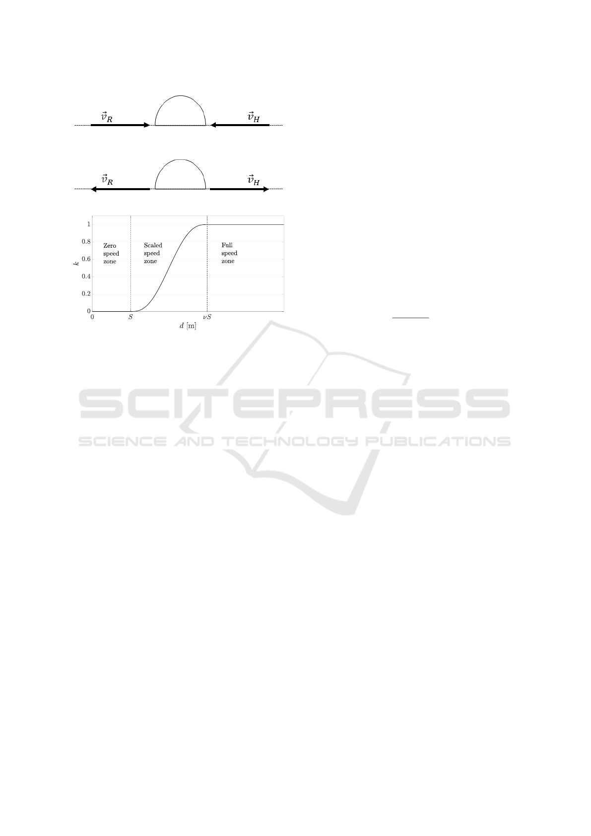
Figure 8: Problem of the scalar product.
Figure 9: Relation between d and k.
5 TRAJECTORY SCALING
SSM scenarios usually sacrifice the production time
because a lot of time is spent in low speed mode
when a human operator is inside the collaborative
workspace. On the contrary, the proposed strategy en-
sures human-robot coexistence according to the stan-
dard regulations, and also guarantees the task effi-
ciency by using a time-scaling approach to change
robot operating speed without introducing accelera-
tion discontinuities.
A typical industrial pre-programmed task, T , is
composed by N positions ˜q
i
, associated to veloci-
ties
˙
˜q
i
, accelerations
¨
˜q
i
and time instants
˜
t
i
with i =
1, . . . , N. Typically, the pre-programmed joint posi-
tions have to be interpolated according to the sam-
pling time T
c
required by the robot control interface.
In this work a quintic interpolation is used, i.e., the
planned interpolated trajectory is
˜q
h
= p
5
(t
h
; T ) (12)
˙
˜q
h
= p
4
(t
h
; T ) (13)
t
h+1
= t
h
+ T
c
, (14)
where t
h
is the h-th discrete time instant, p
4
is the
derivative of the polynomial p
5
, ˜q
h
and
˙
˜q
h
are the
planned joint position and velocity at time t
h
, respec-
tively.
The proposed method modulates the robot speed
by scaling the time with a safety scale factor k, which
can assume values in the interval [0, 1]. The scale fac-
tor is related to d (Section 3.3) as shown in Figure 9.
When d is below the minimum protective distance S,
k is 0 and the robot stops. When the distance d is far
from S, i.e. d > νS (ν > 1), the robot can move at full
speed to improve the production time. Between S and
νS the function in Figure 9 smoothly varies to avoid
acceleration discontinuities. Obviously, ν is another
design parameter that changes the size of the scaled
speed mode zone.
Practically, the trajectory is scaled computing (12)
using a scaled time τ
h
, i.e.,
q
h
= p
5
(τ
h
; T ) τ
h+1
= τ
h
+ kT
c
, (15)
where q
h
is the actual joint command at time t
h
. Ob-
viously, the joint command q
h
, as well as the scaled
time τ
h
, are generated with sampling time T
c
.
This approach effectively scales the joints veloci-
ties. In fact, using (15), it is
˙
τ ≈
τ
h+1
− τ
h
T
s
= k. (16)
By time differentiating (15), (17) demonstrates
that the velocity is scaled by the safety factor k,
˙q
h
= p
4
(τ
h
; T )k.. (17)
This approach guarantees that the task T remains
the same in position, but, simultaneously, the result-
ing velocity is scaled according to k.
When the operator is going to be into a dangerous
situation, the robot operates at diminished capacity
with limits on velocity that respect human-robot col-
laboration norms, until restoration of the safety con-
ditions. Note that the side effect of the velocity re-
duction is the reduction of the minimum protective
distance S, since this value is proportional to the robot
velocity. Experimental results are shown in Section 6.
6 EXPERIMENTAL RESULTS
AND VALIDATION
This section shows an example of experimental re-
sults obtained by simulating an SSM human-robot
collaboration task inside the collaborative workspace
of Figure 2. A manufacturing industrial sealing oper-
ation has been virtually realized: the robot executes
a pre-planned path at a given nominal speed, while,
suddenly, a human operator enters the collaborative
workspace to perform some manual operation close
to the robot, at different distances.
The main goal of this experiment is to prove the
efficiency of the fuzzy inference approach into in-
dustrial applications to better handle the production
time and, at the same time, to guarantee the safety of
A Fuzzy Inference Approach to Control Robot Speed in Human-robot Shared Workspaces
85
the operators when they are inside the collaborative
workspace.
Table 2 summarizes the used hardware and the ex-
perimental case study.
Table 2: Case study and available hardware.
Robot Yaskawa SIA5F
Collaborative workspace 4x2 m
Depth camera (1) Microsoft Kinect v1
Depth camera (2) Intel RealSense D435
Robot simulated task Sealing operation
Operator simulated task Manual piece change
The covariance matrix Q
2
in (7) has been chosen
as
Q
2
= diag(0.02, 0.05, 0.05)m
2
/s
2
, (18)
while the noise covariance has been estimated by ac-
quiring a constant human position as
N = diag(0.0009, 0.0008, 0.001)m
2
. (19)
The parameters to compute the protective separa-
tion distance S of (3) and (11) are reported in Table 3.
The value of C has been chosen to better appreciate
the zero speed zone.
Table 3: Constant parameters of S.
T
R
0.10s
T
S
0.08s
B 0.563mm
Z
R
0.001m
Z
S
0.1067m
C 0.20m
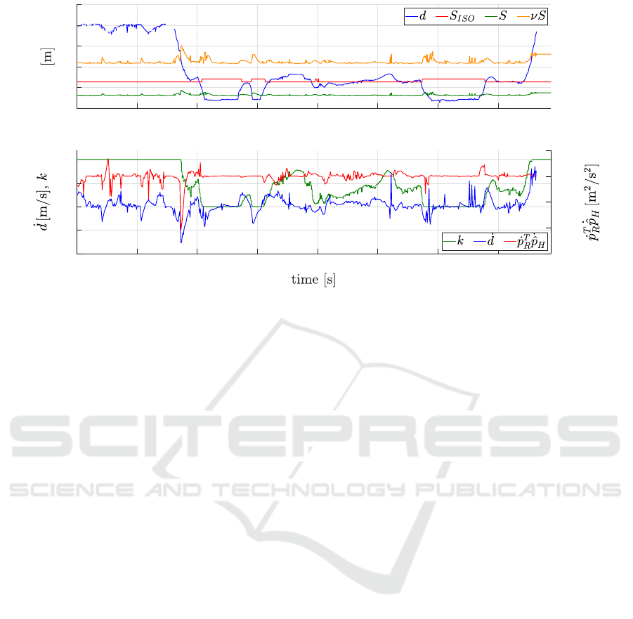
Figure 10 shows the results of the experiment. The
graph at the top of the figure shows the distance be-
tween the human operator and the robot and it can
be compared with the minimum protective distance
computed as in 3 (S
ISO
in the legend) and the two
thresholds proposed in this paper: S in the legend is
the protective distance computed as in (11) and νS
is the threshold used in the trajectory scaling algo-
rithm (Section 5). The bottom plot of Figure 10 shows
the two inputs of the fuzzy inference system (
˙
d and
˙p
T
R
˙
ˆp
H
) and the trajectory scale factor k. In this exper-
iment S
ISO
is not used and it is showed in the plot for
comparison purposes. A video of the experiment is
available at https://youtu.be/RzLZ6RQBPCY.
The robot executes a planned task, suddenly (at
about 16s) an operator enters into the workspace sim-
ulating a manual task. This is visible in the top plot of
Figure 10, where the human-robot distance decreases.
Note that for almost the whole task duration the sep-
aration distance robot-operator is below the S
ISO
sig-
nal, this would have caused frequent starts and stops
of the robot. Instead, through the proposed trajectory
scaling algorithm, the robot reduces its velocity ac-
cording to the observed separation distance. This is
visible in the k signal of the bottom plot that varies
according to d. Notice that k goes to 0 only when
the distance d goes below the protective distance S.
Moreover, another property of the proposed solution
is that S increases only when the distance decreases
(i.e., when
˙
d < 0) and not when the distance increases.
This is due to the computation of the directed speed
and the fuzzy rules. The shown experiment and the
related video demonstrate how the proposed approach
guarantees a safe human-robot coexistence in the col-
laborative workspace. This is achieved both in ac-
cordance with the ISO/TS regulations and minimizing
dead times in the production process.
7 CONCLUSIONS
The human-robot interaction and their intentions to
compete or cooperate in collaborative workspaces are
challenging research fields. The purpose of this work
is to improve the current regulations both to maxi-
mize the production time and guarantee the safety of
human operators inside the shared workspace. The
expected human movements relative to the robot are
classified to identify all possible industrial SSM sce-
narios from which fuzzy rules for the robot reactions
are derived. Collisions between robot and human op-
erators are avoided by identifying human-robot in-
tersections through a detection algorithm which pro-
cesses data obtained by merging two depth camera
images. Results obtained from experimental data
show the applicability of the presented methods to
many common manufacturing industry applications.
ACKNOWLEDGEMENTS
This work has received funding from the Clean Sky
Horizon 2020 Programme under the LABOR project,
grant agreement n. 785419.
REFERENCES
Bascetta, L., Ferretti, G., Rocco, P., Ardo, H., Bruyninckx,
H., Demeester, E., and Lello, E. D. (2011). Towards
safe human-robot interaction in robotic cells: An ap-
proach based on visual tracking and intention estima-
tion. In 2011 IEEE/RSJ International Conference on
Intelligent Robots and Systems. IEEE.
ICINCO 2019 - 16th International Conference on Informatics in Control, Automation and Robotics
86
0 10 20 30 40 50 60 70
0
0.5
1
1.5
2
2.5
0 10 20 30 40 50 60 70
-1
-0.5
0
0.5
1
-0.15
-0.1
-0.05
0
0.05
Figure 10: Experiment: an operator enters the shared workspace while the robot is moving. The top plot shows the estimated
distance robot-operator (d), the protective distances proposed by the regulation without sensing (S
ISO
) and the protective
distances proposed by the paper (S and νS). The bottom plot shows the trajectory scaling factor k, the time derivative of the
distance
˙
d and the scalar product of velocities.
Bicchi, A., Peshkin, M. A., and Colgate, J. E. (2008). Safety
for physical human–robot interaction. In Springer
Handbook of Robotics, pages 1335–1348. Springer
Berlin Heidelberg.
Bjerkeng, M., Falco, P., Natale, C., and Pettersen, K. Y.
(2014). Stability analysis of a hierarchical architec-
ture for discrete-time sensor-based control of robotic
systems. IEEE Transactions on Robotics, 30(3):745–
753.
Blodow, N. (2012). Realtime urdf filter.
Bosscher, P. and Hedman, D. (2009). Real-time collision
avoidance algorithm for robotic manipulators. In 2009
IEEE International Conference on Technologies for
Practical Robot Applications. IEEE.
Choi, S. I. and Kim, B. K. (1999). Obstacle avoid-
ance control for redundant manipulators using coll-
idability measure. In Proceedings 1999 IEEE/RSJ
International Conference on Intelligent Robots and
Systems. Human and Environment Friendly Robots
with High Intelligence and Emotional Quotients (Cat.
No.99CH36289). IEEE.
Fischler, M. A. and Bolles, R. C. (1981). Random sample
consensus: a paradigm for model fitting with appli-
cations to image analysis and automated cartography.
Communications of the ACM, 24(6):381–395.
IEC 60204-1 (2009). Safety of machinery - Electrical
equipment of machines - Part 1: General require-
ments. Technical report, International Electrotechni-
cal Commission.
ISO 10218-1 (2011). Robots and robotic devices - Safety re-
quirements for industrial robots. Part 1: Robots. Tech-
nical report, International Organization for Standard-
ization.
ISO 10218-2 (2011). Robots and robotic devices - Safety
requirements for industrial robots. Part 2: Robot sys-
tem and integration. Technical report, International
Organization for Standardization.
ISO 13855 (2010). Safety of machinery - Positioning of
safeguards with respect to the approach speeds of
parts of the human body. Technical report, Interna-
tional Organization for Standardization.
ISO/TS 15066 (2016). Robots and robotic devices - collab-
orative robots. Technical report, International Organi-
zation for Standardization.
Lippi, M. and Marino, A. (2018). Safety in human-multi
robot collaborative scenarios: a trajectory scaling ap-
proach. IFAC-PapersOnLine, 51(22):190–196.
Ross, T. J. (2010). Fuzzy Logic with Engineering Applica-
tions. John Wiley & Sons, Ltd.
Rusu, R. B. and Cousins, S. (2011). 3d is here: Point cloud
library (PCL). In IEEE International Conference on
Robotics and Automation. IEEE.
The LABOR project (2019). https://www.labor-project.eu/.
Torr, P. and Murray, D. (1997). The development and com-
parison of robust methods for estimating the funda-
mental matrix. International Journal of Computer Vi-
sion, 24(3):271–300.
Zhang, P., Jin, P., Du, G., and Liu, X. (2016). Ensuring
safety in human-robot coexisting environment based
on two-level protection. Industrial Robot: An Inter-
national Journal, 43(3):264–273.
A Fuzzy Inference Approach to Control Robot Speed in Human-robot Shared Workspaces
87
