
Scenario-based Testing of ADAS - Integration of the Open Simulation
Interface into Co-simulation for Function Validation
Nadja Marko
1 a
, Jonas Ruebsam
2 b
, Andreas Biehn
3 c
and Hannes Schneider
2 d
1
VIRTUAL VEHICLE Research Center, Inffeldgasse 21a, Graz, Austria
2
AVL List GmbH, Hans-List-Platz 1, Graz, Austria
3
VIRES Simulationstechnologie GmbH, Grassinger Strasse 8, Bad Aibling, Germany
Keywords:
Advanced Driver Assistence System, Co-simulation, Simulation Framework, Verification & Validation,
Functional Mock-up Interface, Open Simulation Interface.
Abstract:
Testing Advanced Driver Assistance Systems (ADAS) is challenging, as the environmental conditions that
appear in reality are manifold and complex. Testing only on the road is not feasible since it is expensive
and difficult to reproduce results. Additional virtual tests based on environment simulations are therefore
required. These simulations are based on scenarios representing real world situations that provide ground
truth data to sensors or sensor models for the environmental perception. To integrate environment simulations
with function simulations, object lists and sensor raw data need to be exchanged and have to be processed
by the function under test. Various simulators for automated driving exist that provide different, not uniquely
defined interfaces. The Open Simulation Interface (OSI) is a specification that describes a generic interface
for the environmental perception of automated driving functions. In this paper, we describe a co-simulation
framework in which OSI is applied for testing an ADAS. The co-simulation framework is based on generic,
standardized interfaces and uses existing tools that we extended with OSI to couple environment simulations
with function simulations. With a realistic co-simulation setup, that have been defined by industry partners,
we tested the applicability of OSI and describe the results here.
1 INTRODUCTION
Advanced Driver Assistance Systems (ADAS) are
complex mechatronic systems which support the
driver in various driving situations and increase driv-
ing comfort. A high automation grade leads to an in-
creased development and test effort as the recognition
and interpretation of the surrounding environment is
required. Different sensors (e.g. radar, lidar, cam-
era) are used to capture the state of the environment
and advanced algorithms are needed to interpret the
results of different sensors. Further, safety of these
functions has to be guaranteed as they often influence
basic driving functions.
The verification and validation (V&V) of such
complex systems is a challenging task. If testing
and assessment methods cannot keep pace with the
a
https://orcid.org/0000-0002-6604-8483
b
https://orcid.org/0000-0002-6895-9387
c
https://orcid.org/0000-0002-5027-4726
d
https://orcid.org/0000-0002-1093-5403
functional growth, they will become the bottleneck
for the introduction of ADAS to the market (Maurer
and Winner, 2013). Testing on the proving ground
and on real roads is cost and time intensive. More-
over, test results are difficult to reproduce. Additional,
simulation-based V&V methods are needed to han-
dle the increasing number of tests that are required to
ensure safe functionality. With scenario-based test-
ing, virtual environment scenarios are developed and
simulated. The environment simulation must provide
a realistic model of the static and dynamic elements
in the scenario (road, scenery and actors). As a re-
sult, the simulation produces ground truth data needed
for the validation of ADAS functions. Further, sensor
perception models have to be integrated into the sim-
ulation to simulate not only the ground truth but also
real sensor behavior as this represents the input the
ADAS gets in reality.
To connect environment simulations with function
simulations a defined interface is needed. The Open
Simulation Interface (OSI) defines a tool-independent
interface for the exchange of environmental percep-
Marko, N., Ruebsam, J., Biehn, A. and Schneider, H.
Scenario-based Testing of ADAS - Integration of the Open Simulation Interface into Co-simulation for Function Validation.
DOI: 10.5220/0007838302550262
In Proceedings of the 9th International Conference on Simulation and Modeling Methodologies, Technologies and Applications (SIMULTECH 2019), pages 255-262
ISBN: 978-989-758-381-0
Copyright
c
2019 by SCITEPRESS – Science and Technology Publications, Lda. All rights reserved
255

tion data. The generic specification ensures mod-
ularity, integrability and interchangeability of sim-
ulation components. In this paper we describe a
co-simulation framework that integrates environment
simulation, a sensor model and an ADAS function
using OSI. This co-simulation framework is based
on existing tools that have been extended with OSI.
Therefore, methods and tools have been adapted to be
able to couple binary data like object lists or sensor
low level data. The whole setup has been evaluated in
an industry-driven demonstrator within the European
research project Enable-S3. The demonstrator func-
tionality is distributed via three platforms, in which
AVL’s co-simulation platform Model.CONNECT acts
as integration master. VIRES Virtual Test Drive
(VTD) is used as environment simulation tool in
which scenarios can be generated and simulated. The
produced ground truth data is modified by a sensor
model that generates an adapted object list to repre-
sent real sensor behavior. Based on this data, an ACC
function (ADAS), which regulates the distance to the
front vehicle, can be validated. Additionally, a visu-
alization component implemented in the Robot Op-
erating System (ROS) is part of the simulation and
visualizes ground truth and sensor data to enable data
inspection. For the integration between the simula-
tion components OSI is applied for the exchange of
ground truth and sensor data. Thus, we collected
first experiences with the arising OSI standard and de-
scribe its applicability and first evaluation results.
The paper is structured as follows. Chapter 2 de-
scribes the used co-simulation standards and gives
an overview of related work. In chapter 3 the co-
simulation framework and all simulation components
for testing our ADAS function are described in more
detail. Chapter 4 summarizes the results we made
with OSI for validating the ADAS function. Finally,
chapter 5 gives a summary of this paper and an out-
look for the next steps.
2 RELATED WORK &
STANDARDS
Virtual testing for ADAS requires new interfaces
for co-simulations, in order to support complex data
types like sensor data. Therefore, the use of a stan-
dardized interfaces provides flexibility and integrabil-
ity.
The Functional Mock-up Interface (FMI) is a tool
independent, standardized interface to support model
exchange and co-simulation of simulation models. It
has been developed in the MODELISAR project and
was first published in 2010. The current version is
FMI 2.0 (2014) (Blochwitz et al., 2012). FMI is a de-
facto standard and has not undergone a standardiza-
tion process yet. However, this specification is widely
accepted as it is supported by many tools (Modelica,
2018). To be compliant to the specification, an FMU
has to implement all functions defined in the specifi-
cation. This includes methods for accessing data and
for controlling the simulation model. At the moment,
only the exchange of simple data types (real, integer,
boolean and string) is supported. In future versions
binary data, necessary for exchanging object lists, im-
ages or other type of sensor data, will be defined as
well.
The ACOSAR project (Krammer et al., 2016) de-
veloped an advanced co-simulation interface for dis-
tributed simulation which can be applied for soft-
ware and for hardware integration. The outcome of
the project is the specification of the Distributed Co-
simulation Protocol (DCP) (Krammer et al., 2018)
which is released via the Modelica Association
1
that
also publishes the FMI specification. In contrast to
FMI, the DCP specifies a communication layer for
co-simulation which enables the integration of real-
time systems and a standardized co-simulation in dis-
tributed setups. The main differences to FMI are a
protocol based data exchange, the integration of real-
time systems into the simulation is possible, and a
slave to slave communication is enabled.
The Open Simulation Interface (OSI)
2
is an up-
coming standard which describes data structures for
the environmental perception of automated driving
functions in virtual driving scenarios. The interface
enables the connection between environment sim-
ulation frameworks and function simulation frame-
works as well as the integration of sensor mod-
els. OSI is message based and contains differ-
ent top level messages. For sensor models, in
particular the OSI messages OSI::SensorData and
OSI::SensorView are of interest. OSI::SensorView
contains the OSI::GroundTruth data which is com-
puted in the environment simulation and is used as
input for sensor models. It is based on a global ref-
erence frame but may be limited to an area of in-
terest surrounding a given sensor position. Using
this OSI::GroundTruth data, a sensor model usually
applies coordinate transformation and sensor behav-
ior on this data. The output contains all the per-
ceived objects and their coordinates in the sensor ref-
erence frame. This updated object list is part of
the OSI::SensorData message. OSI does not define
which messages have to be used nor how to access
these messages but provides a defined structure. This
1
https://www.modelica.org/
2
https://github.com/OpenSimulationInterface/
SIMULTECH 2019 - 9th International Conference on Simulation and Modeling Methodologies, Technologies and Applications
256

means that OSI is independent of the data exchange
protocol. Therefore, OSI Sensor Model Packaging
(OSMP) defines how OSI sensor models have to be
packaged as FMU 2.0 for use in simulations and
which messages need to be handled for different types
of models (e.g. environmental effect models or sensor
models). Every OSMP compliant model consumes a
top level OSI message and produces a top level mes-
sage. More detailed information regarding standard-
ization of sensor interfaces for automated driving, in
simulation (OSI) and for real vehicles (ISO23150), is
given in (Driesten and Schaller, 2019).
There are also some simulation frameworks de-
scribed for testing ADAS. In (Schneider and Saad,
2018) OSI and FMI are used for a tool chain that
combines various integration platforms and authoring
tools. Therefore, they use OSI for describing the en-
vironment semantics including a camera model which
is the main focus of the paper. (Schaermann et al.,
2017) developed a tool chain for the virtual validation
of ADAS where the validation of virtual perception
sensor models in the field of automated driving is fo-
cused. For their integration of VTD and ROS, they
use OSI. (Hanke et al., 2015) presents a generic ar-
chitecture for simulation of ADAS sensors. This ar-
chitecture also includes a list of properties that a simu-
lation framework should provide for detected objects
and sensor targets. These properties reflect the OSI
structure but indeed OSI is more sophisticated. They
also support the idea to have well-defined interfaces
to provide a flexible simulation framework. (Elghar-
bawy et al., 2016) presents also a generic architecture
for verification of multi-sensor data fusion. Their pro-
posed modular software architecture is based on FMI.
No more details are given regarding the interfaces.
(Feilhauer and H
¨
aring, 2016) describes a simulation
architecture for validation of ADAS. This architecture
is based on FMI. However, they state that FMI has to
be extended to support complex data types (object list,
image streams) needed for ADAS simulation which
also reflects our experiences. Their concept is based
on modern game engines in which all environmental
perceptions (vehicles, road, pedestrians) are classified
as simulation objects with the same properties.
3 CO-SIMULATION
FRAMEWORK FOR ADAS
TESTING
In order to validate automated driving functions
with simulation, we had to extend an existing co-
simulation framework and a driving simulator for en-
vironment simulations in order to provide sensor data
to the function under test. Therefore, a proof of con-
cept demonstrator has been setup which implements
a realistic test setup and enables the evaluation of our
concept. In this section we describe all the compo-
nents of the test setup with focus on the integration of
them using OSI.
3.1 Co-simulation Setup
For the demonstrator, we setup a co-simulation in
which the integration of the following components
has been realized:
• Co-simulation integration platform
• Environment simulation application
• Sensor model
• ADAS function
• Sensor data visualization
The co-simulation setup is distributed via three
platforms. On the first platform, VIRES VTD is run-
ning which generates the ground truth (cp. Figure 3).
On the second platform, the co-simulation platform
Model.CONNECT is running that acts as simulation
master and coordinates the whole simulation. More-
over, a simple sensor model has been implemented
that should represent realistic sensor behaviour in-
stead of the perfect sensor. This sensor model as well
as the automated driving function, an ACC model,
and the vehicle dynamics are executed on this plat-
form. On the third platform, the ROS visualization
component is running. Figure 1 shows an overview of
the demonstrator setup.
Figure 1: Demonstrator architecture.
The integration of the platforms as well as the sen-
sor model is based on the Open Simulation Interface.
This specification defines the data structure for the en-
vironmental perception. It enables the integration of
function simulation with environment simulation by
using a generic and tool independent interface. A
main contribution of this paper is the analysis and
evaluation of OSI version 3.
Figure 2 shows the OSI messages we use in the
proof-of-concept demonstrator. VIRES VTD gen-
Scenario-based Testing of ADAS - Integration of the Open Simulation Interface into Co-simulation for Function Validation
257

erates OSI::GroundTruth data that which is con-
tained in the top level message OSI::SensorData.
The sensor model uses this information, which
contains for example object lists and environmen-
tal conditions, and adds sensor data in form of
OSI::DetectedMovingObject messages. This mes-
sage class can directly be found in OSI::SensorData.
Currently, only object lists are exchanged as first trial
for using OSI.
Figure 2: OSI messages.
3.2 Co-simulation Integration Platform
For the demonstrator AVL’s open model integration
and co-simulation platform Model.CONNECT
TM3
is
used as simulation master. The simulation master
controls the whole simulation process and coordi-
nates the different simulation models to build a con-
sistent virtual prototype. It assures that all elements
of the demonstrator setup are executed at the right
time and that the interfaces are synched accordingly.
However, integration methods are based on simple
data types such as integers or doubles. For testing
ADAS functions, object lists or sensor raw data have
to be exchanged during the simulation. Therefore,
Model.CONNECT has been extended to support a bi-
nary data interface as defined for OSMP (cp. Section
2). It should be noted that binary data interfaces will
be specified in version 3.0 of the FMI standard. In the
meantime we use OSMP.
The simulation scenario for the demonstrator is
setup in Model.CONNECT as follows. The commu-
nication with VTD and Model.CONNECT is imple-
mented via a TCP communication channel to allow
for simulation on different computers. Via this chan-
nel we exchange vehicle dynamics and OSI ground
truth simulation data. For the vehicle dynamics, the
VTD proprietary RDB format is used. The sensor
model, which is connected to Model.CONNECT via
the implemented binary port, uses the ground truth
in OSI format. The output of the sensor model, the
OSI sensor data, is connected to the ACC function,
which is implemented and integrated as FMU. The
ACC FMU is furthermore connected to a vehicle dy-
namics model to override throttle and break pedal in
case the ACC function is activated. The input for
3
https://www.avl.com/web/guest/-/model-connect-
the vehicle dynamics simulation contains information
like contact points of the wheelbase and road proper-
ties. The vehicle dynamics is executed in AVL’s VSM
tool to simulate realistic vehicle behavior. This tool is
coupled to Model.CONNECT via a proprietary inter-
face. In return, VTD receives updates for heading,
speed and position, as well as throttle and break pedal
states. Finally, the OSI data, ground truth and sensor
data, is transferred via a binary port over a TCP com-
munication channel to the ROS framework for visual-
ization of OSI data (see Section 3.6).
3.3 Environment Simulation
The main task of the environment simulation is the
generation of realistic ground truth data, based on the
selected scenario. The output of the environment sim-
ulation varies from general simulation data to simple
and complex object lists and beyond to realistic low
level sensor data. For the demonstrator VTD is used
as environment simulation software, which covers the
full range from the generation of 3d content to the
simulation of complex traffic scenarios and, finally, to
the simulation of either simplified or physically driven
sensors. Environment simulation requires a concrete
scenario as input which contains several levels of in-
formation. This includes the environment itself and
the behavior of simulation entities within this envi-
ronment. VTD uses the OpenSCENARIO
4
file for-
mat for the description of concrete scenarios. Open-
SCENARIO is an approach, aiming for an open stan-
dardized exchange format for automotive scenarios.
The scenario describes the static and dynamic envi-
ronment and the dynamic behavior of entities. For
the demonstrator a relatively simple highway scenario
with a limited number of movable objects was cho-
sen. The road network represents a typical straight
European highway. So called swarm traffic with 200
vehicles was set up for this scenario allowing for a
changeable number of perceived objects.
Figure 3: VTD simulation with ’ideal’ sensor.
4
https://www.asam.net/standards/detail/openscenario/
SIMULTECH 2019 - 9th International Conference on Simulation and Modeling Methodologies, Technologies and Applications
258
VTD has built in functionality for interfacing sen-
sor models as well as mechanisms for TCP/IP net-
work communication. A so called perfect sensor was
set up in VTD, which is able to create object list out-
put in a user definable perception area around the sen-
sor mounting position. The perfect sensor is able to
perceive all objects and their ground truth data within
a given sensor cone. The parameters of this cone,
e.g. field of view, near and far clipping planes, can
be modified during run time and have been used to
adjust the number of objects perceived by the sensor.
The extension of VTD consisted of three tasks:
Integration of OSI into VTD. Installing OSI is
straight forward and the existing interface in VTD al-
lows for easy integration of user written C++ plug-ins.
Both together allowed an unproblematic connection
of VTD and OSI, without requiring any changes in
VTD core components.
Mapping of VTD object list to OSI data model.
The data model of OSI fits pretty well with VTD’s
data model. Most of the objects attributes can be
found on both interfaces. In general, OSI covers less
information for objects, environment and infrastruc-
ture. Noteworthy are the differences in the road/lane
model. VTD and its internal interface completely
are based on OpenDRIVE
5
, whereas OSI has a de-
viating lane model, which is hard to translate to and
from OpenDRIVE. For our demonstrator fortunately
the lane model was not in the main focus.
Implementation of a network interface for OSI.
To allow for connecting to the simulation master, a
network interface was required. OSI has no built-in
mechanism for network communication. For practical
reasons we used the OSMP serialization method for
the OSI network interface. To ensure data integrity,
TCP/IP was chosen as protocol. Therefore, an addi-
tional data field was required to indicate the size of
the network message on the network receiver side.
3.4 Sensor Model
The task of the sensor model is to convert the global
ground truth, received form the environment simula-
tion, to a detected object list. In this process environ-
mental conditions like precipitation, fog and sensor
attributes like the field of view, are considered.
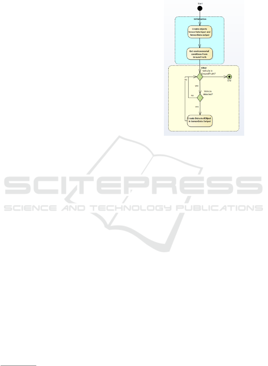
The model created for the demonstrator is an ex-
tension of the generic OSI OSMP implementation and
written in C++. It can be easily integrated into any co-
simulation framework, which supports the FMI stan-
dard. For every time step the do-step function inside
the FMU is executed, as shown in Figure 4.
5
https://www.asam.net/standards/detail/opendrive/
Figure 4: Sensor model algorithm.
In one time step the following sub-steps are exe-
cuted:
1. Read input data stream and unpack the binary data
into OSI::SensorData
2. Extract the environmental conditions into param-
eters
3. Create a transformation to relative coordinates
with respect to the ego car
4. Apply the filter function to all objects in the
ground truth
5. For every detected object create a corresponding
object in the OSI::SensorData message
The filter function algorithm is based on a sim-
ple phenomenological model. Initially, the objects in
the ground truth are filtered by a cone, with variable
detection range d
max
and field of view. These are usu-
ally set to about 100m and 40
◦
. In the next step a
filter based on the parameter set of the OSI environ-
mental conditions {F,P,I ∈ [0, 1]} is created, with the
normalized fog F, precipitation P and illumination I.
The detection criteria for an object is now fulfilled by
d
rel
= f
1
(F) · f
2
(P) · f
3
(I) ·d
max
(1)
d
Veh
< d
rel
(2)
where d
rel
is defined as the reduced detection dis-
tance, d
Veh
as the relative distance to the ego car
and f
1/2/3
are linear functions. In particular these
functions are chosen to align the detections with the
visual output of the environment simulation, there
Scenario-based Testing of ADAS - Integration of the Open Simulation Interface into Co-simulation for Function Validation
259

is no relation to real sensor hardware. In a fi-
nal step, detection errors are added from a gaussian
N (0[m],1[m]). If detected, an object is added to
the OSI::DetectedMovingObject message, inside the
OSI::SensorData message.
3.5 ADAS (ACC Function)
The ACC model is implemented in Matlab Simulink
and exported as FMU. For the demonstrator the func-
tion was implemented as a simple PID controller
which has only the P, I, D parameters and the speed of
the Ego vehicle as well as the distance to the leading
vehicle (from the simulation environment) as inputs.
The output of the function is the speed of the ego ve-
hicle. Furthermore, the desired velocity and a safety
distance can be set as parameters.
Since OSI does not include the input variables to
the ACC function, additional calculations are neces-
sary to identify the nearest car on the same lane. This
is implemented by evaluating the relative orientation
of all cars and then choose the one with the smallest
distance on the same lane.
3.6 Visualization
The verification of the ADAS function is mainly
shown with the environment simulation in VTD
and sensor model and ADAS functionality in
Model.CONNECT
TM
. However, in order to evaluate
OSI and to evaluate the simulation results easier, the
OSI data is visualized in ROS as well. The visual-
ization shows the transferred ground truth and sensor
data (object lists) in 2d space and represents what the
sensor can see (cp. Figure 5). The OSI data is re-
ceived via an implemented TCP socket and after de-
serialization, the OSI data is mapped to an internal de-
fined data structure. This data structure is very similar
to OSI and builds the basis for sensor data visualiza-
tion (also real sensor data). Based on the sensor data,
Figure 5: Visualization of OSI objects in ROS (Left) in
comparison to VTD (Right), undetected objects are marked
as green, detected as red.
ROS marker messages are generated and visualized
in rviz, which represents the visualization tool in the
ROS environment.
4 RESULTS
The setup of the demonstrator shows the capability
of a closed-loop simulation tool chain for the valida-
tion of an ACC function. In particular, the usabil-
ity of the newly introduced OSI interface is of inter-
est. Therefore, we analyzed the performance and ad-
dressed benefits but also challenges when using OSI.
4.1 OSI Performance
Beside the usability and integration capabilities of
OSI, the performance of the interface needs to be as-
sessed. It has to be ensured that an integration into
different XiL systems does not lead to a slowdown. In
particular for HiL, it is important to preserve real-time
capabilities. With the execution of the demonstrator,
some important properties can already be observed.
With respect to a simulation time step of ∆t = 0.02[s]
the overall real-time factor R of the co-simulation is
always R < 1, during the simulation. Overall the
simulation runs above 50 Hz at all times. From this
first observation the requirements for real-time sys-
tems seem fulfilled.
The next step is to measure the time complexity
for data transmission and performing calculations on
OSI messages. This should be done with reference
to the number of objects and the message size in or-
der to exclude a possible limiting behavior during run
time. For an evaluation of the OSI performance, pro-
filer functions have been added to the sensor model.
The first timer measures the conversion time from
reading a binary input stream into a Google proto-
buf object. The second timer measures the time for
executing the functions of the sensor model. This
includes the coordinate transformation, the parsing
of environmental conditions and the filtering of ob-
jects. For the performance benchmark, the ego car
was placed behind a large bulk of 200 vehicles. By
varying the detection range of the ground truth data
between d = [0m, 200m] and ∆d = 1m, the number
of cars in the SensorData object and consequently the
size of the OSI message changes. From the profil-
ing measurement it can be observed, that the time for
one time step is highly non-deterministic and depen-
dent of CPU clock and other processes running on the
computer. The maximum time observed for executing
a time step was of order ∝ 10
−3
. To obtain a more reli-
able result, the profiling measurements were averaged
SIMULTECH 2019 - 9th International Conference on Simulation and Modeling Methodologies, Technologies and Applications
260

over a duration of 50000 time steps, as shown in Fig-
ure 6. It can be seen that the run time for all functions
increases linearly of O(N). The data parsing from an
binary input takes around twice the time in compari-
son to the execution of the sensor functions. Overall
the run time stays in the order of ∝ 10
−4
, for N < 200.
This benchmark is a first approval of the perfor-
mance of OSI for XiL based use cases. However, for
further evaluation it would be interesting to increase
the message complexity by adding stationary objects,
like traffic signs, lanes and most importantly low level
sensor data.
4.2 Experiences OSI
In addition to the performance of OSI, we evaluated
the specification for relevant viewpoints and summa-
rize the results we made with OSI here.
Redundancy. Data is stored redundantly in some
cases. For example, the OSI::SensorView message
exists for all sensors and every OSI::SensorView con-
tains OSI::GroundTruth. Further, low level sensor
data has different representations and can be found
in OSI::SensorView and/or OSI::FeatureData.
Environmental Conditions. At the moment, weather
information is defined with enumerations, but for sen-
sor models continuous values would be helpful and
enable a better representation of sensor behavior.
Sensor Low Level Data. OSI defines
OSI::SensorView as root message for other sen-
sor data messages. In our case, this concept would
not work for a sensor model based on low level data as
OSI::SensorView only contains Cartesian points for
Lidar data. It is possible to convert the data, but this
goes along with errors. We used OSI::SensorData
as root message instead. This message contains
OSI::SensorView and OSI::FeatureData and thus,
provides both representations of low level data. As a
consequence, we are not fully compliant to OSI.
0 50 100 150 200
N
0
1
2
3
4
5
hRi
t
± σ
R
[s]
×10
−4
Sensor Functions
ParseFromArray
Figure 6: Averaged runtime hRi
t
with variance σ
R
for OSI
based sensor functions and data parsing, with respect to the
current number of moving objects N in the ground truth.
Ambiguity. All fields in OSI messages are optional
and hence, does not need to be filled. On the one hand,
this is advantageous as messages can be kept smaller
and performance can be improved. On the other hand,
OSI is no plug and play standard as users must agree
beforehand which data is exchanged.
Consistency. The data structure of OSI itself is con-
sistent. However, OSI definitions are not consistent
to other standards, for example OpenSCENARIO.
Moreover, the performance of OSI is dependent on
Google protocol buffers which does not guarantee
the same performance for different programming lan-
guages (e.g. Pyhton, C++). We experienced that
the standard Python implementation is much slower.
Nevertheless, there are workarounds to handle this is-
sue.
Maturity. Though the work on the specification has
not finished until now, OSI version 3 is specified very
detailed and the concepts are sophisticated. Never-
theless, OSI has not been tested exhaustively and the
practicality will be shown when OSI will be applied
in various tools and simulation scenarios.
Applicability. OSI is specified for virtual scenarios
in the Automotive domain. However, OSI addresses
the emerging standard ISO 23150 for real sensor in-
terfaces and thus, will be applicable also for real sen-
sors.
Completeness/Additional Functionality. OSI de-
fines messages for the environmental perception of
automated driving functions in virtual scenarios and
does not include data structures for maps or vehicle
dynamics, for example. Working with OSI we discov-
ered the following missing things that could be help-
ful:
• Place holder for additional data (e.g. tool relevant
data)
• Sensor low level data is not completely defined
• Lane model is not complete for all usages
• Possibility to send packed data (e.g. for sensor
low level data) could improve performance
• Libraries to support additional functionality (e.g
for coordinate transformation or data filtering)
• Extended environment conditions (e.g field for
size of rain drop)
Usability. The OSI structure has to be examined to
understand the concept. OSI and Google protobuf
needs to be installed. Therefore, OSI needs to be com-
piled and existing compiler and linker errors must be
resolved manually (e.g. there could be problems if
several protobuf libraries are installed as the correct
library must be linked). All in all, there is a prepa-
ration time needed to get OSI running. This could
Scenario-based Testing of ADAS - Integration of the Open Simulation Interface into Co-simulation for Function Validation
261

be improved for example with a Debian package. As
soon as OSI is running, it is easy to use.
5 CONCLUSION
In this paper, a co-simulation setup is described using
the Open Simulation Interface for testing automated
driving functions. Generic and standardized inter-
faces help to reduce the integration effort and enable
flexibility and interchangeability. OSI defines such a
generic interface to describe environment and sensor
data for validating automated driving functions in vir-
tual scenarios. In a demonstrator, developed within
the European research project Enable-S3, we vali-
dated an ACC function based on co-simulation tech-
niques. The demonstrator is based on standardized
interfaces to provide a modular and flexible simula-
tion framework in which scenarios, simulation units
and the function under test can easily be exchanged.
Therefore, we used OSI to connect an environment
simulation application, a sensor model and a visu-
alization component to validate ADAS functionality.
We had to extend tools to be able to exchange com-
plex data types, such as object lists, which was nec-
essary to test automated driving functions. Based on
this co-simulation setup, we analyzed OSI v3 with re-
gard to content and performance. We think OSI is a
promising specification and is also considered to be-
come an ASAM
6
standard. For the demonstrator we
used OSI on object list level. As a next step we would
like to analyze this interface specification with sen-
sor low level data. Further, we work on an imple-
mentation of the Distributed Co-Simulation Protocol
to be used instead of the TCP connection. This en-
ables a standardized distributed simulation and sup-
ports hence interchangeability and interoperability.
ACKNOWLEDGEMENTS
This work has been conducted within the ENABLE-
S3 project that has received funding from the ECSEL
JOINT UNDERTAKING under GRANT AGREE-
MENT No 692455. This JOINT UNDERTAKING
receives support from the European Union’s HORI-
ZON 2020 RESEARCH AND INNOVATION PRO-
GRAMME and Austria, Denmark, Germany, Finland,
Czech Republic, Italy, Spain, Portugal, Poland, Ire-
land, Belgium, France, Netherlands, United King-
dom, Slovakia, Norway. The publication was writ-
ten at VIRTUAL VEHICLE Research Center in Graz
6
https://www.asam.net/
and partially funded by the COMET K2 – Compe-
tence Centers for Excellent Technologies Programme
of the Federal Ministry for Transport, Innovation and
Technology (bmvit), the Federal Ministry for Dig-
ital, Business and Enterprise (bmdw), the Austrian
Research Promotion Agency (FFG), the Province of
Styria and the Styrian Business Promotion Agency
(SFG).
REFERENCES
Blochwitz, T., Otter, M., Akesson, J., Arnold, M., Claus-
zlig, C., Elmqvist, H., Friedrich, M., Junghanns, A.,
Mauszlig, J., Neumerkel, D., Olsson, H., and Viel,
A. (2012). Functional mockup interface 2.0: The
standard for tool independent exchange of simula-
tion models. In Proceedings of the 9th International
MODELICA Conference, number 76, pages 173–184.
Link
¨
oping University Electronic Press.
Driesten, C. v. and Schaller, T. (2019). Overall approach to
standardize ad sensor interfaces: Simulation and real
vehicle. In Bertram, T., editor, Fahrerassistenzsysteme
2018, pages 47–55, Wiesbaden. Springer Fachmedien
Wiesbaden.
Elgharbawy, M., Schwarzhaupt, A., Scheike, G., Frey, M.,
and Gauterin, F. (2016). A generic architecture of
adas sensor fault injection for virtual tests. In 2016
IEEE/ACS 13th International Conference of Com-
puter Systems and Applications (AICCSA), pages 1–7.
Feilhauer, M. and H
¨
aring, J. (2016). A multi-domain simu-
lation approach to validate advanced driver assistance
systems. In 2016 IEEE Intelligent Vehicles Sympo-
sium (IV), pages 1179–1184.
Hanke, T., Hirsenkorn, N., Dehlink, B., Rauch, A.,
Rasshofer, R., and Biebl, E. (2015). Generic architec-
ture for simulation of adas sensors. In 2015 16th In-
ternational Radar Symposium (IRS), pages 125–130.
Krammer, M., Benedikt, M., Blochwitz, T., Alekeish, K.,
Amringer, N., Kater, C., Materne, S., Ruvalcaba,
R., Schuch, K., Zehetner, J., Damm-Norwig, M.,
Schreiber, V., Nagarajan, N., Corral, I., Sparber, T.,
Klein, S., and Andert, J. (2018). The distributed co-
simulation protocol for the integration of real-time
systems and simulation environments.
Krammer, M., Marko, N., and Benedikt, M. (2016). Inter-
facing real-time systems for advanced co-simulation -
the acosar approach. In STAF 2016: Software Tech-
nologies: Applications and Foundations.
Maurer, M. and Winner, H. (2013). Automotive Systems
Engineering. Springer Publishing Company, Incorpo-
rated.
Modelica (2018). FMI functional mockup interface. https:
//fmi-standard.org/. Accessed: 2018-08-24.
Schaermann, A., Rauch, A., Hirsenkorn, N., Hanke, T.,
Rasshofer, R., and Biebl, E. (2017). Validation of ve-
hicle environment sensor models. In 2017 IEEE Intel-
ligent Vehicles Symposium (IV), pages 405–411.
Schneider, S.-A. and Saad, K. (2018). Camera behav-
ioral model and testbed setups for image-based ADAS
functions. e & i Elektrotechnik und Informationstech-
nik, pages 1–7. issn: 1613-7620.
SIMULTECH 2019 - 9th International Conference on Simulation and Modeling Methodologies, Technologies and Applications
262
